US213959A - Improvement in car-starters - Google Patents
Improvement in car-starters Download PDFInfo
- Publication number
- US213959A US213959A US213959DA US213959A US 213959 A US213959 A US 213959A US 213959D A US213959D A US 213959DA US 213959 A US213959 A US 213959A
- Authority
- US
- United States
- Prior art keywords
- car
- pawls
- cylinder
- ratchet
- sections
- Prior art date
- Legal status (The legal status is an assumption and is not a legal conclusion. Google has not performed a legal analysis and makes no representation as to the accuracy of the status listed.)
- Expired - Lifetime
Links
- 239000007858 starting material Substances 0.000 title description 8
- 241001474033 Acar Species 0.000 description 1
- 150000001875 compounds Chemical class 0.000 description 1
- 238000010276 construction Methods 0.000 description 1
- 230000000694 effects Effects 0.000 description 1
- 230000004048 modification Effects 0.000 description 1
- 238000012986 modification Methods 0.000 description 1
Images
Classifications
-
- F—MECHANICAL ENGINEERING; LIGHTING; HEATING; WEAPONS; BLASTING
- F02—COMBUSTION ENGINES; HOT-GAS OR COMBUSTION-PRODUCT ENGINE PLANTS
- F02N—STARTING OF COMBUSTION ENGINES; STARTING AIDS FOR SUCH ENGINES, NOT OTHERWISE PROVIDED FOR
- F02N5/00—Starting apparatus having mechanical power storage
- F02N5/02—Starting apparatus having mechanical power storage of spring type
Definitions
- This invention relates to certain improvements in car-starters, designed for utilizing a certain portion of the power expended in stopping the horse-car, and, when desired, to cause the stored-up power to be exerted as a motor in starting the car, as will be hereinafter more fully set forth, and pointed out in the claim.
- Figure 1 is a plan view, showing the under frame of a car and my improved car-starter applied.
- Fig. 2 is a section on line was of Fig. 1.
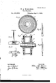
- Fig. 3 is a plan of the starter, showing cylinders and ratchets.
- Fig. 4 is a side elevation of Fig. 3.
- Figs. 5 and 6 are modifications of the pawls; Fig. 7, cross-section of starter-cylinders on line y 3 of Fig. 3; Fig. 8, section along the axle and through the starter; and
- Figs. 9, 10, 11, and 12 represent means of starting the pawl-actuating mechanism.
- the cylinder composed of parts or sections A and B, is placed on the axle of the ordinary car.
- the outer part, A is provided with the spring-connection a and the cylinder part B with the second connection, If, for the spring 0, as is shown by Fig. 7.
- the spring 0 is incased between the upper and lower cylinder parts and the sides thereof, and held at each end by the connections a and b
- the cylinder-sections are provided with ratchets a ⁇ and b connected to the said cylinder-sections as part thereof or firmly attached thereto.
- ratchets are arranged so as to engage the pawls in contrary directions, and act against the force of the spring 0 or a system of springs 0, held by a number of connections, a and b
- a and b To hold the cylinder-sections A and B (formed as shown) in position on the axle, two collars, D and E, are required.
- These collars are pinned or keyed on the axle, and have a flange, which faces up or abuts to the sides of the cylinder-sections, so as to allow them to revolve freely; and at the outer edge of the flanges of the collars D and E are attached ratchets d and 0
- These ratchets are arranged so as to be in contrary directions on the shaft or axle, so that the ratchet-faces engage their pawls d c in contrary directions, and said pawls d e are upon the sides of the sections A and B, and are arranged so that their outer projecting ends, (1 and a shall be actuated or controlled by the action of ratcheted rings F and G.
- the pawl f 2 is forced back on the ratchet-ring F, and, by continuing to operate the levers of the said system I, the second pawl, a becomes engaged with the ratchet a and the forcing back of this ratchet a against the spring causes the pawl a to pass out of engagement, thereby releasing the said spring and causing its force to be exerted on the axle with the desired effect; and as the pawls g and b are in the position contrary to the released side A the car is moved in that direction, and to move it in the opposite direction or to operate the pawls the levers K or Wheel and pinion L may be operated.
- the pawls may be made sliding, as is shown by the drawings.
- the devices for starting can be made to act in either direction, so that power gained with the car going in one direction may be used to start it back, or in the same direction in which it was moving pre- "ious to putting the starting apparatus into operation.
- a car-starter provided with coil-springs for the purpose of starting acar, the fixed collars I) and E, holding in position laterally the cylinder-sections A and B, provided with coilspring and ratchet-teeth a b, ratchets d ratchet-rings F G, pawls d, and lever-systems II and I, operating in the manner as herein set forth.
Landscapes
- Engineering & Computer Science (AREA)
- Chemical & Material Sciences (AREA)
- Combustion & Propulsion (AREA)
- Mechanical Engineering (AREA)
- General Engineering & Computer Science (AREA)
- Professional, Industrial, Or Sporting Protective Garments (AREA)
Description
2 Sheata -Sheet 1.
W. A. WARRINER. Gar-Starter.
No. 213,959. Patented April 1,1879.
fu j.
N. FEIEHS. FHOTO-UTHOGRAPHEFI, WASHINGTON, D. C.
2 Sheets-Shee.t 2-. W. A. WARRINER.
' Gar-Starter.
No. 213,959, Patented April I, 187 9.
" IIIIIIIIIII lillllilil FLf/Z w DP 51 G I WITI'|ESSES.' lqvsqmn,
UNITED STATES PATENT OEEIcE WILLIAM A. WARRINER, OF FRANKLIN TOWNSHIP, GLOUCESTER COUNTY, NEW JERSEY.
IMPROVEMENT IN CAR-STARTERS.
Specification forming part of Letters Patent No. 213,959, dated April 1, 1879; application filed December 4, 1878.
To all whom it may concern:
Be it known that I, WILLIAM ALLEN WAR- RINER, of Franklin township, in the county of Gloucester and State of New Jersey, have invented certain new and useful Improvements in Gar-Starters; and I do hereby declare that the following is a full, clear, and exact description of the invention, which will enable others skilled in the art to which it appertains to make and use the same, reference being had to the accompanying drawings, and to letters of reference marked thereon, which form a part of this specification.
This invention relates to certain improvements in car-starters, designed for utilizing a certain portion of the power expended in stopping the horse-car, and, when desired, to cause the stored-up power to be exerted as a motor in starting the car, as will be hereinafter more fully set forth, and pointed out in the claim.
Figure 1 is a plan view, showing the under frame of a car and my improved car-starter applied. Fig. 2 is a section on line was of Fig. 1. Fig. 3 is a plan of the starter, showing cylinders and ratchets. Fig. 4 is a side elevation of Fig. 3. Figs. 5 and 6 are modifications of the pawls; Fig. 7, cross-section of starter-cylinders on line y 3 of Fig. 3; Fig. 8, section along the axle and through the starter; and Figs. 9, 10, 11, and 12 represent means of starting the pawl-actuating mechanism.
To enable those skilled in the artto make and use myinvention, I will proceed to describe its construction and operation.
The cylinder, composed of parts or sections A and B, is placed on the axle of the ordinary car. The outer part, A, is provided with the spring-connection a and the cylinder part B with the second connection, If, for the spring 0, as is shown by Fig. 7. The spring 0 is incased between the upper and lower cylinder parts and the sides thereof, and held at each end by the connections a and b The cylinder-sections are provided with ratchets a} and b connected to the said cylinder-sections as part thereof or firmly attached thereto. These ratchets are arranged so as to engage the pawls in contrary directions, and act against the force of the spring 0 or a system of springs 0, held by a number of connections, a and b To hold the cylinder-sections A and B (formed as shown) in position on the axle, two collars, D and E, are required. These collars are pinned or keyed on the axle, and have a flange, which faces up or abuts to the sides of the cylinder-sections, so as to allow them to revolve freely; and at the outer edge of the flanges of the collars D and E are attached ratchets d and 0 These ratchets are arranged so as to be in contrary directions on the shaft or axle, so that the ratchet-faces engage their pawls d c in contrary directions, and said pawls d e are upon the sides of the sections A and B, and are arranged so that their outer projecting ends, (1 and a shall be actuated or controlled by the action of ratcheted rings F and G. (See Fig. 3.) These rings are held to the side of the cylinder-sections A and B by means of cleats, provided with the springs f (Only one shown, see Fig. 4.) These are for the purpose of operating said rings, and these rings again, in their turn, operate the ends of the pawls d and e also, in connection with the said cylinder-sections and their connections there are arranged two systems of levers or pawls, H and I. On the system H are the pawls f and a and on the system I are the counter-pawls g and If. The pawl f of the system H engages the ratchet on the ring F, and the pawl 0. the ratchet of the cylinder-section A, and the pawl g the ratchet of the ring G of system I. There is also the second pawl, b of the same system engaging with the ratchet of the cylinder-section B. By the arrangement of compound levers the pawl f 2 is forced back on the ratchet-ring F, and, by continuing to operate the levers of the said system I, the second pawl, a becomes engaged with the ratchet a and the forcing back of this ratchet a against the spring causes the pawl a to pass out of engagement, thereby releasing the said spring and causing its force to be exerted on the axle with the desired effect; and as the pawls g and b are in the position contrary to the released side A the car is moved in that direction, and to move it in the opposite direction or to operate the pawls the levers K or Wheel and pinion L may be operated. The pawls may be made sliding, as is shown by the drawings.
The operation of the invention is simply that, by the action of the shaft or axle, one or the other of the cylinder-sections A or B will be carried forward, according to the motion of the car, and, by the action of the collars l) or E through the pawl e or (I said collars being stationary on the axle, will carrythe cylindersection along and wind up the spring, and, by the return or force-back action on the pawls, will disengage the axle and hold the force stored, to be released by the before-mentioned action of forcing back the ratchets.
It is obvious that the devices for starting can be made to act in either direction, so that power gained with the car going in one direction may be used to start it back, or in the same direction in which it was moving pre- "ious to putting the starting apparatus into operation.
Having thus described my invention, what I claim as new, and desireto secure by Letters Patent, is-
ln a car-starter provided with coil-springs for the purpose of starting acar, the fixed collars I) and E, holding in position laterally the cylinder-sections A and B, provided with coilspring and ratchet-teeth a b, ratchets d ratchet-rings F G, pawls d, and lever-systems II and I, operating in the manner as herein set forth.
In testimony that I claim the foregoing as my own I aflix my signature in presence of two witnesses.
WILLIAM ALLEN VVARRINER.
Witnesses:
BENJ. C. POLE, Jom. COLE.
l l l
Publications (1)
| Publication Number | Publication Date |
|---|---|
| US213959A true US213959A (en) | 1879-04-01 |
Family
ID=2283363
Family Applications (1)
| Application Number | Title | Priority Date | Filing Date |
|---|---|---|---|
| US213959D Expired - Lifetime US213959A (en) | Improvement in car-starters |
Country Status (1)
| Country | Link |
|---|---|
| US (1) | US213959A (en) |
Cited By (2)
| Publication number | Priority date | Publication date | Assignee | Title |
|---|---|---|---|---|
| US20090182539A1 (en) * | 2008-01-14 | 2009-07-16 | Fujitsu Limited | Multi-objective optimal design support device, method and program storage medium |
| US20090182695A1 (en) * | 2008-01-14 | 2009-07-16 | Fujitsu Limited | Multi-objective optimal design support device and method taking manufacturing variations into consideration |
-
0
- US US213959D patent/US213959A/en not_active Expired - Lifetime
Cited By (2)
| Publication number | Priority date | Publication date | Assignee | Title |
|---|---|---|---|---|
| US20090182539A1 (en) * | 2008-01-14 | 2009-07-16 | Fujitsu Limited | Multi-objective optimal design support device, method and program storage medium |
| US20090182695A1 (en) * | 2008-01-14 | 2009-07-16 | Fujitsu Limited | Multi-objective optimal design support device and method taking manufacturing variations into consideration |
Similar Documents
| Publication | Publication Date | Title |
|---|---|---|
| US213959A (en) | Improvement in car-starters | |
| US413330A (en) | Maker | |
| US381393A (en) | Car-starter | |
| US442700A (en) | Car brake and starter | |
| US348306A (en) | Den willson | |
| US213872A (en) | Improvement in car-starters | |
| US230506A (en) | Car brake and starter | |
| US197247A (en) | Improvement in car-starters | |
| US530150A (en) | Car-starter | |
| US315620A (en) | higley | |
| US301096A (en) | Car-brake | |
| US145076A (en) | Improvement in gar-starters | |
| US263363A (en) | Car-starter | |
| US414729A (en) | Brake-latch | |
| US358642A (en) | Car-starter | |
| US279049A (en) | Car-starter | |
| US255238A (en) | Car-starter | |
| US249486A (en) | sampson | |
| US193435A (en) | Improvement in car brakes and starters | |
| US48339A (en) | Improvement in devices for releasing screw-engines | |
| US225382A (en) | Lewis s | |
| US232043A (en) | Car-starter | |
| US414183A (en) | Car starter and brake | |
| US263529A (en) | johnson | |
| US259013A (en) | Vania |