US2139587A - Signal lamp - Google Patents
Signal lamp Download PDFInfo
- Publication number
- US2139587A US2139587A US194468A US19446838A US2139587A US 2139587 A US2139587 A US 2139587A US 194468 A US194468 A US 194468A US 19446838 A US19446838 A US 19446838A US 2139587 A US2139587 A US 2139587A
- Authority
- US
- United States
- Prior art keywords
- casing
- cylinder
- disc
- compartments
- lamp
- Prior art date
- Legal status (The legal status is an assumption and is not a legal conclusion. Google has not performed a legal analysis and makes no representation as to the accuracy of the status listed.)
- Expired - Lifetime
Links
- 238000005192 partition Methods 0.000 description 18
- 230000002093 peripheral effect Effects 0.000 description 3
- 238000010276 construction Methods 0.000 description 2
- 238000004519 manufacturing process Methods 0.000 description 1
- 230000004048 modification Effects 0.000 description 1
- 238000012986 modification Methods 0.000 description 1
Images

Classifications
-
- B—PERFORMING OPERATIONS; TRANSPORTING
- B60—VEHICLES IN GENERAL
- B60Q—ARRANGEMENT OF SIGNALLING OR LIGHTING DEVICES, THE MOUNTING OR SUPPORTING THEREOF OR CIRCUITS THEREFOR, FOR VEHICLES IN GENERAL
- B60Q1/00—Arrangement of optical signalling or lighting devices, the mounting or supporting thereof or circuits therefor
- B60Q1/26—Arrangement of optical signalling or lighting devices, the mounting or supporting thereof or circuits therefor the devices being primarily intended to indicate the vehicle, or parts thereof, or to give signals, to other traffic
- B60Q1/2607—Arrangement of optical signalling or lighting devices, the mounting or supporting thereof or circuits therefor the devices being primarily intended to indicate the vehicle, or parts thereof, or to give signals, to other traffic comprising at least two indicating lamps
Definitions
- This invention relates to signal lamps particularly adapted for use on motor vehicles, and has for an object to provide a signal lamp so constructed that the intentions of the driver will be unmistakably indicated to vehicles in traffic.
- a further object is to provide a signal lamp having a plurality of compartments concentrically disposed around a common axis and bearing respective legends as Stop, Back, "Left and Right, and a central compartment coaxially arranged with the radial compartments and divided into upper and lower compartments, all of the compartments being adapted to be illuminated selectivelyr by respective lamp bulbs under control of the driver.
- a further object is to provide a signal lamp of this type which will be formed of a few strong simple and durable parts, which will be inexpensive to manufacture and which will not easily get out of order. y y
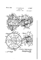
- Figure 1 is a longitudinal sectional view of a signal lamp constructed in accordance with the invention.
- Figure 2 is a front elevation of the signal lamp shown in Figure 1.
- Figure 3 is a longitudinal sectional view of the signal lamp taken on the line 3-3 of Figure 1 looking in the direction of the arrows.
- Figure 4 is a cross sectional view of the signal lamp taken on the line 4-4 of Figure 1 looking in the direction of the arrows.
- Figure 5 is a cross sectional View taken on the line 5-5 of Figure 1 looking in the direction of the arrows.
- Figure 6 is a cross sectional view taken on the line 6-6 of Figure 1 looking in the direction oi the arrows.
- Figure '7 is a perspective View looking toward the front of the cylinder, discs, and partitions forming the compartments in the lamp.
- Figure 8 is a detail perspective view looking toward the back of the cylinder, discs and partitions forming compartments in the lamp.
- I0 designates a substantially frusto-conical lamp casing, the same being provided at the bottom with a mounting foot II.
- a cylinder I2 is arranged in the casing in axial alignment with the casing. 5
- a disc I4 surrounds the cylinder and is 1ocated between the front and rear ends of the cylinder.
- the disc is formed integral with the cylinder and is provided near the peripheral edge with openings I5 to receive securing bolts 10 IB which are passed into threaded openings I1 in the peripheral edge of the casing I0, as best shown in Figure 3.
- a plurality of substantially triangular partitions IB are secured 15 to the front side of the disc and to the outer surface of the cylinder.
- the cylinder, disc and partitions form a plurality of radial compartments I9, 20, 2l and 22.
- a frusto-conical lens member 23 is secured to the casing by screws 24 20 and stenciledto display the legends Stop, Right, Back and Left, corresponding to respective ones of the compartments I9 to 22 inclusive, as best shown in Figure 2.
- Transparent distinctively colored backings 25 25 are arranged in rear of the stenciled legends in the compartments and are held in place by spring clips 26 and preferably the Stop legend backing is colored red, the Right legend backing is colored purple, they Back legend backing is col- 30 ored green and the Left legend backing is colored red.
- the cylinder I2 is provided at the rear end with a pair of oppositely disposed arms 21 which are secured at the rear ends to a disc 28, as best 35 shown in Figures 7 and 8.
- the disc is smaller in diameter than thedisc I4 and is secured to the rear end of the lamp casing I0.
- a horizontally disposed partition 29 extends from front to rear of the cylinder I2 and then is 40 continued rearwardly between the arms 21 to the rear disc 28, this partition being also extended trough the arms as shown at 30 in Figure 8.
- the partition 29 divides the cylinder into upper and lower compartments 32 and 33 and also di- 45 vides the lamp casing back of the disc I4 into upper and lower compartments 34 and 35, as best shown in Figure 1.
- the iront semi-circular ends of the compartments in the cylinder are closed by semi- 50 circular transparent panes 3E, and 31, best shown in Figure 2, there being a circular rim 38 integral with the frusto-conical lens member 23 provided with a cross bar 39 having clips 40 to hold the panes in place. 55
- Respective lamp bulbs 4I and 42 are mounted on the rear disc 28 respectively above and below the partition 29 and these bulbs shine through and illuminate the respective panes 36 and 31 which are both preferably colored red, the upper pane being the conventional tail light while the lower pane may be the conventional brake pedal operated light of the vehicle and may display the legend Slow.
- the casing I is cut away at the top and bottom adjacent the bulbs 4l and 42 and the cut away portions are provided with cut away panes 43 and 44 which are held at the ends by angular clips 45 and 46 formed integral with the casing and also are prevented from dislodgment longitudinally of the casing by clips 41 and 48.
- the respective bulbs 4l and 42 shine through the panes 43 and 44 and indicate that the signal lamp is in good working order as far as concerns the tail light and brake pedal operated light.
- Lamp bulbs 49 to 52 inclusive Arranged in the signal compartments I9 to 22 inclusive are respective lamp bulbs 49 to 52 inclusive as best shown in Figure 4, these bulbs being secured to the disc I4.
- the lead wires of these bulbs as well as the lead wires of the bulbs d! and 42 are carried in a cable 53 through an opening 54 in the casing I0, as best shown in Figure 1.
- a switch within convenient reach of the driver may be used to control the circuit wires selectively for energizing the signal lamps to indicate the intentions of the driver.
- a signal lamp comprising a substantially frusto-conical casing, a cylinder arranged in the casing in axial alignment therewith, a disc secured to the cylinder intermediate the ends thereof and secured at the peripheral edge to the casing, a plurality of substantially triangular partitionsrsecured to the front side of the disc and to the upper surface of the cylinder, a rustoconical lens member secured to the casing, said disc and partitions forming a plurality of concentrically disposed compartments, there being signal legends corresponding to the compartments on said lens member, a centrally located partition in said cylinder extending into said casing and forming upper and lower compartments in the cylinder and in the casing, panes closing the front ends of said compartments, and ,signal lamps in all of said compartments adapted to illuminate the signal legends and the panes.
- a signal lamp comprising a substantially frusto-conical lamp casing, a, mounting foot secured to the casing, a cylinder arranged axially in the casing and provided at the rear end with oppositely disposed arms, a disc secured to the cylinder adjacent to said arms and secured to the front end of the casing, a second disc of smaller diameter than the rst named disc secured to the ends of said arms and to said casing, a horizontally disposed partition extending axially in said cylinder and between said arms, said partition having extensions projecting from said arms and extending to the sides of the casing, triangular shaped partitions secured to the front side of the first named disc and to the outer surface of the cylinder and forming a plurality of radially disposed signal compartments, a substantially frusto-conical lens member connected to the casing and bearing signal legends corresponding to respective ones of the signal compartments, lamp bulbs secured to the rst named disc for illuminating the signal legends, lamp bulbs secured to the second named disc for
- a signal lamp comprising a substantially frusto-conical lamp casing, a mounting foot secured to the casing, a cylinder arranged axially in the casing and provided at the rear end with oppositely disposed arms, a disc secured to the cylinder adjacent to said arms and secured to the front end of the casing, a second disc of smaller diameter than the iirst named disc secured to the ends of said arms and to said casing, a horizontally disposed partition extending axially in said cylinder and between said arms, said partition having extensions projecting from said arms and extending to the sides of the casing, triangular shaped partitions secured to the front side of the rst named disc and to the outer surface of the cylinder and forming a plurality of radially disposed signal compartments, a substantially frusto-conical lens member connected to the casing and bearing signal legends corresponding to the respective signal compartments, lamp bulbs secured to the rst named disc for illuminating the signal legends, lamp bulbs secured to the second named
Landscapes
- Engineering & Computer Science (AREA)
- Mechanical Engineering (AREA)
- Non-Portable Lighting Devices Or Systems Thereof (AREA)
Description
c. F. HUSEMOLLER 2,139,587
SIGNAL LAMP Dec. 6, 1933.
Filed March '7, 1938 2 Sheets-Sheet l ATTO R N EYS cuz. F. HUSEMQLLER- 2313957 SIGNAL `LAMP Dec., l, 193s.
Filed March 7, 1938 sheets-sheet 2 IIII Patented Dec. 6, 1938 `UMTED STATES PAT-ENT OFFICE SIGNAL LAMP Christian F. Husemoller, Washington, D'. .0.
Application March 7, 1938, Serial No. 194,468
3 Claims.
This invention relates to signal lamps particularly adapted for use on motor vehicles, and has for an object to provide a signal lamp so constructed that the intentions of the driver will be unmistakably indicated to vehicles in traffic.
A further object is to provide a signal lamp having a plurality of compartments concentrically disposed around a common axis and bearing respective legends as Stop, Back, "Left and Right, and a central compartment coaxially arranged with the radial compartments and divided into upper and lower compartments, all of the compartments being adapted to be illuminated selectivelyr by respective lamp bulbs under control of the driver.
A further object is to provide a signal lamp of this type which will be formed of a few strong simple and durable parts, which will be inexpensive to manufacture and which will not easily get out of order. y y
With the above and other objects in view the invention consists of certain novel `details of construction and combinations of parts hereinafter fully described and claimed, it being understood that various modifications may be resorted to within the scope of the appended claims without departing from the spirit or sacrificing any of the advantages of the invention.
In the accompanying drawings forming part of this specification,
Figure 1 is a longitudinal sectional view of a signal lamp constructed in accordance with the invention.
Figure 2 is a front elevation of the signal lamp shown in Figure 1.
Figure 3 is a longitudinal sectional view of the signal lamp taken on the line 3-3 of Figure 1 looking in the direction of the arrows.
Figure 4 is a cross sectional view of the signal lamp taken on the line 4-4 of Figure 1 looking in the direction of the arrows.
Figure 5 is a cross sectional View taken on the line 5-5 of Figure 1 looking in the direction of the arrows.
Figure 6 is a cross sectional view taken on the line 6-6 of Figure 1 looking in the direction oi the arrows.
Figure '7 is a perspective View looking toward the front of the cylinder, discs, and partitions forming the compartments in the lamp.
Figure 8 is a detail perspective view looking toward the back of the cylinder, discs and partitions forming compartments in the lamp.
Referring now to the drawings in which like characters of reference designate similar parts in the various views, I0 designates a substantially frusto-conical lamp casing, the same being provided at the bottom with a mounting foot II. A cylinder I2 is arranged in the casing in axial alignment with the casing. 5
A disc I4 surrounds the cylinder and is 1ocated between the front and rear ends of the cylinder. The disc is formed integral with the cylinder and is provided near the peripheral edge with openings I5 to receive securing bolts 10 IB which are passed into threaded openings I1 in the peripheral edge of the casing I0, as best shown in Figure 3.
A plurality of substantially triangular partitions IB, best shown in Figure '7, are secured 15 to the front side of the disc and to the outer surface of the cylinder. The cylinder, disc and partitions form a plurality of radial compartments I9, 20, 2l and 22. A frusto-conical lens member 23 is secured to the casing by screws 24 20 and stenciledto display the legends Stop, Right, Back and Left, corresponding to respective ones of the compartments I9 to 22 inclusive, as best shown in Figure 2.
Transparent distinctively colored backings 25 25 are arranged in rear of the stenciled legends in the compartments and are held in place by spring clips 26 and preferably the Stop legend backing is colored red, the Right legend backing is colored purple, they Back legend backing is col- 30 ored green and the Left legend backing is colored red.
The cylinder I2 is provided at the rear end with a pair of oppositely disposed arms 21 which are secured at the rear ends to a disc 28, as best 35 shown in Figures 7 and 8. The disc is smaller in diameter than thedisc I4 and is secured to the rear end of the lamp casing I0.
A horizontally disposed partition 29 extends from front to rear of the cylinder I2 and then is 40 continued rearwardly between the arms 21 to the rear disc 28, this partition being also extended trough the arms as shown at 30 inFigure 8. The partition 29 divides the cylinder into upper and lower compartments 32 and 33 and also di- 45 vides the lamp casing back of the disc I4 into upper and lower compartments 34 and 35, as best shown in Figure 1.
Preferably the iront semi-circular ends of the compartments in the cylinder are closed by semi- 50 circular transparent panes 3E, and 31, best shown in Figure 2, there being a circular rim 38 integral with the frusto-conical lens member 23 provided with a cross bar 39 having clips 40 to hold the panes in place. 55
Respective lamp bulbs 4I and 42 are mounted on the rear disc 28 respectively above and below the partition 29 and these bulbs shine through and illuminate the respective panes 36 and 31 which are both preferably colored red, the upper pane being the conventional tail light while the lower pane may be the conventional brake pedal operated light of the vehicle and may display the legend Slow.
As best shown in Figures 1 and 5 the casing I is cut away at the top and bottom adjacent the bulbs 4l and 42 and the cut away portions are provided with cut away panes 43 and 44 which are held at the ends by angular clips 45 and 46 formed integral with the casing and also are prevented from dislodgment longitudinally of the casing by clips 41 and 48. The respective bulbs 4l and 42 shine through the panes 43 and 44 and indicate that the signal lamp is in good working order as far as concerns the tail light and brake pedal operated light.
Arranged in the signal compartments I9 to 22 inclusive are respective lamp bulbs 49 to 52 inclusive as best shown in Figure 4, these bulbs being secured to the disc I4. The lead wires of these bulbs as well as the lead wires of the bulbs d! and 42 are carried in a cable 53 through an opening 54 in the casing I0, as best shown in Figure 1.
In operation a switch within convenient reach of the driver may be used to control the circuit wires selectively for energizing the signal lamps to indicate the intentions of the driver.
From the above description it is thought that the construction and operation of the invention will be fully understood without further explanation.
What is claimed is:
l. A signal lamp comprising a substantially frusto-conical casing, a cylinder arranged in the casing in axial alignment therewith, a disc secured to the cylinder intermediate the ends thereof and secured at the peripheral edge to the casing, a plurality of substantially triangular partitionsrsecured to the front side of the disc and to the upper surface of the cylinder, a rustoconical lens member secured to the casing, said disc and partitions forming a plurality of concentrically disposed compartments, there being signal legends corresponding to the compartments on said lens member, a centrally located partition in said cylinder extending into said casing and forming upper and lower compartments in the cylinder and in the casing, panes closing the front ends of said compartments, and ,signal lamps in all of said compartments adapted to illuminate the signal legends and the panes.
2. A signal lamp comprising a substantially frusto-conical lamp casing, a, mounting foot secured to the casing, a cylinder arranged axially in the casing and provided at the rear end with oppositely disposed arms, a disc secured to the cylinder adjacent to said arms and secured to the front end of the casing, a second disc of smaller diameter than the rst named disc secured to the ends of said arms and to said casing, a horizontally disposed partition extending axially in said cylinder and between said arms, said partition having extensions projecting from said arms and extending to the sides of the casing, triangular shaped partitions secured to the front side of the first named disc and to the outer surface of the cylinder and forming a plurality of radially disposed signal compartments, a substantially frusto-conical lens member connected to the casing and bearing signal legends corresponding to respective ones of the signal compartments, lamp bulbs secured to the rst named disc for illuminating the signal legends, lamp bulbs secured to the second named disc for illuminating the interior of the lamp casing in rear of the rst named disc and illuminating the upper and lower compartments formed in said cylinder by said horizontal partition, and panes closing the front ends of said upper and lower compartments of the cylinder.
3. A signal lamp comprising a substantially frusto-conical lamp casing, a mounting foot secured to the casing, a cylinder arranged axially in the casing and provided at the rear end with oppositely disposed arms, a disc secured to the cylinder adjacent to said arms and secured to the front end of the casing, a second disc of smaller diameter than the iirst named disc secured to the ends of said arms and to said casing, a horizontally disposed partition extending axially in said cylinder and between said arms, said partition having extensions projecting from said arms and extending to the sides of the casing, triangular shaped partitions secured to the front side of the rst named disc and to the outer surface of the cylinder and forming a plurality of radially disposed signal compartments, a substantially frusto-conical lens member connected to the casing and bearing signal legends corresponding to the respective signal compartments, lamp bulbs secured to the rst named disc for illuminating the signal legends, lamp bulbs secured to the second named disc for illuminating the interior of the lamp casing in rear of the rst named disc and illuminating the upper and lower compartments formed in said cylinder by said horizontal partition, panes closing the front ends of said upper and lower compartments of the cylinder, and arcuate panes in the top and bottom of the casing illuminated by the Signal lamps secured to the second named disc.
Y CHRISTIAN F. I-IUSEMOLLER`
Priority Applications (1)
| Application Number | Priority Date | Filing Date | Title |
|---|---|---|---|
| US194468A US2139587A (en) | 1938-03-07 | 1938-03-07 | Signal lamp |
Applications Claiming Priority (1)
| Application Number | Priority Date | Filing Date | Title |
|---|---|---|---|
| US194468A US2139587A (en) | 1938-03-07 | 1938-03-07 | Signal lamp |
Publications (1)
| Publication Number | Publication Date |
|---|---|
| US2139587A true US2139587A (en) | 1938-12-06 |
Family
ID=22717716
Family Applications (1)
| Application Number | Title | Priority Date | Filing Date |
|---|---|---|---|
| US194468A Expired - Lifetime US2139587A (en) | 1938-03-07 | 1938-03-07 | Signal lamp |
Country Status (1)
| Country | Link |
|---|---|
| US (1) | US2139587A (en) |
Cited By (3)
| Publication number | Priority date | Publication date | Assignee | Title |
|---|---|---|---|---|
| US2640972A (en) * | 1951-01-15 | 1953-06-02 | Carter Moffett | Directional indicator |
| US5984494A (en) * | 1995-09-08 | 1999-11-16 | Jimmy G. Cook | Light shield for an illumination system |
| US20110052270A1 (en) * | 2009-08-26 | 2011-03-03 | Kyocera Mita Corporation | Developing device and image-forming apparatus provided therewith |
-
1938
- 1938-03-07 US US194468A patent/US2139587A/en not_active Expired - Lifetime
Cited By (3)
| Publication number | Priority date | Publication date | Assignee | Title |
|---|---|---|---|---|
| US2640972A (en) * | 1951-01-15 | 1953-06-02 | Carter Moffett | Directional indicator |
| US5984494A (en) * | 1995-09-08 | 1999-11-16 | Jimmy G. Cook | Light shield for an illumination system |
| US20110052270A1 (en) * | 2009-08-26 | 2011-03-03 | Kyocera Mita Corporation | Developing device and image-forming apparatus provided therewith |
Similar Documents
| Publication | Publication Date | Title |
|---|---|---|
| US1602094A (en) | Combined vehicle signal, spotlight, and mirror | |
| US2139587A (en) | Signal lamp | |
| US2084252A (en) | Automobile indicator | |
| US2675534A (en) | Rear window signals for automobiles | |
| US2110033A (en) | Solenoid actuator for rotating signals | |
| US2194614A (en) | Lens assembly | |
| US1889623A (en) | Combined light and signal | |
| US1671024A (en) | Lamp structure | |
| US1349063A (en) | Automobile-signal | |
| US2315380A (en) | Safety pedal for bicycles | |
| US1873823A (en) | Combination tire carrier and reflecting body | |
| US1956436A (en) | Safety signal light | |
| US1351689A (en) | Combined lamp and signal | |
| US1351913A (en) | Direction-indicator and tail-light for vehicles | |
| US1617035A (en) | Direction signal for automobiles | |
| US1775306A (en) | Automobile signal | |
| US1492139A (en) | Parking lamp for vehicles | |
| US1840790A (en) | Signal light reflector | |
| USRE19990E (en) | Combined vehicle signal | |
| US2031154A (en) | License plate holder for automobiles | |
| US1798966A (en) | Signaling device | |
| US2377419A (en) | Vehicle signal light | |
| US1141776A (en) | Tail-lamp. | |
| US1580766A (en) | Direction signal | |
| US1849695A (en) | Vehicle headlight |