US2139473A - Hydraulic jacking system for vehicles - Google Patents
Hydraulic jacking system for vehicles Download PDFInfo
- Publication number
- US2139473A US2139473A US50531A US5053135A US2139473A US 2139473 A US2139473 A US 2139473A US 50531 A US50531 A US 50531A US 5053135 A US5053135 A US 5053135A US 2139473 A US2139473 A US 2139473A
- Authority
- US
- United States
- Prior art keywords
- pump
- jacks
- clutch
- pump body
- jacking system
- Prior art date
- Legal status (The legal status is an assumption and is not a legal conclusion. Google has not performed a legal analysis and makes no representation as to the accuracy of the status listed.)
- Expired - Lifetime
Links
- 239000012530 fluid Substances 0.000 description 17
- 239000003921 oil Substances 0.000 description 7
- 238000004891 communication Methods 0.000 description 4
- 239000007788 liquid Substances 0.000 description 4
- 230000004048 modification Effects 0.000 description 3
- 238000012986 modification Methods 0.000 description 3
- 238000005086 pumping Methods 0.000 description 3
- 229910000831 Steel Inorganic materials 0.000 description 2
- 239000010959 steel Substances 0.000 description 2
- 238000005452 bending Methods 0.000 description 1
- 238000005266 casting Methods 0.000 description 1
- 230000006835 compression Effects 0.000 description 1
- 238000007906 compression Methods 0.000 description 1
- 230000008878 coupling Effects 0.000 description 1
- 238000010168 coupling process Methods 0.000 description 1
- 238000005859 coupling reaction Methods 0.000 description 1
- 230000000694 effects Effects 0.000 description 1
- 210000004907 gland Anatomy 0.000 description 1
- 239000010705 motor oil Substances 0.000 description 1
- XLYOFNOQVPJJNP-UHFFFAOYSA-N water Substances O XLYOFNOQVPJJNP-UHFFFAOYSA-N 0.000 description 1
Images


Classifications
-
- B—PERFORMING OPERATIONS; TRANSPORTING
- B60—VEHICLES IN GENERAL
- B60S—SERVICING, CLEANING, REPAIRING, SUPPORTING, LIFTING, OR MANOEUVRING OF VEHICLES, NOT OTHERWISE PROVIDED FOR
- B60S9/00—Ground-engaging vehicle fittings for supporting, lifting, or manoeuvring the vehicle, wholly or in part, e.g. built-in jacks
- B60S9/02—Ground-engaging vehicle fittings for supporting, lifting, or manoeuvring the vehicle, wholly or in part, e.g. built-in jacks for only lifting or supporting
- B60S9/10—Ground-engaging vehicle fittings for supporting, lifting, or manoeuvring the vehicle, wholly or in part, e.g. built-in jacks for only lifting or supporting by fluid pressure
- B60S9/12—Ground-engaging vehicle fittings for supporting, lifting, or manoeuvring the vehicle, wholly or in part, e.g. built-in jacks for only lifting or supporting by fluid pressure of telescopic type
Definitions
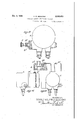
- This invention relates to hydraulic jacking sys- Figure 8 is a sectional view of the part of the tems: for vehicles of the kind in which a pump pump control devices which are situated adjadelivers high pressure -fluid which is utilized for cent to the dashboard:
- Figure 9 is a sectional view on the line 9-9 of the vehicle.
- Figure 10 is a sectional View similar to Figure vention an annular piston type of pump of the 8, but showing a modified arrangement; kind described in the specification of Patent No.
- Figure 11 is a sectional view similar to Figure 4 1,997,233 can be coupled to the engine or other but illustrating a modified arrangement adapted in driving part directly or by means of a clutch acfor use with the arrangement of Figure 10;
- I0 tuated bya key or other control member adapted Figure 12 is a View similar to Figure 10 but to be actuated by the driver. showing a further modification;
- Figure 13 illustrates a pump having the control the invention the pump, which is preferably aldevice mounted on it adjacent thereto; 1.3 though not essentially of the annular piston type, Figures 14 and 15 are side and end elevational 1 5 is associated with such a clutch and also with a views respectively of the pump attached to an release valve which controls release of pressure electric motor for driving the pump.
- the pump A is mounted on the vehicle in a reservoirs, and the clutch and release valves are suitable position according to the part from which if connected to a common control member whereby it is to be driven.
- the pump A is operation of the control member brings about shown attached to a dynamo B to which it can the desired operation, both of the clutch and of be coupled, and in Figures 14 and 15 it is shown the valve.
- the pump may be designed for attachment to the vehicle batteries B
- the driving and stopthe back of a dynamo or dynamo drive and may ping of the pump is effected through a control :be designed to form a continuation of the dynamo on the dashboard indicated generally at D which casing.
- the pump may be coupled is connected by a low pressure device D such as to the usual drive of the fan, water pump, igniapipe or cable (but preferably not a high pressure tion distributor, engine oil pump, revolution counfluid line) to the pump, or by a control D (Figter or to the cam shaft, crank shaft, or other ure 13) mounted on the pump adjacent thereto.
- the pump draws oil from a reservoir E through a motor driven for example from the vehicle batpip El and r s t oil through a discharge teries and may be coupled directly or by means pipe E into a horizontal pipe line E and flexible of a belt, chain, shaft, flexible shaft, or other tubes E E to a pair of hydraulically operated drive.
- the pump comprises a main casting or body A tem in accordance with the invention; and a cap A held on to the body by bolts A
- FIG 2 is a sectional View of the pump on the of which bolts also serve for attaching the pump lines 2--2 of Figure 3; to the dynamo, electric motor, or other appro- 43
- Figure 3 is a sectional View of the pump on the priate part.
- a pump spindle A Mounted about centrally in the 45 line f Figure pump body A is a pump spindle A carrying a Figure 4 is a sectional view on the line 4--4 of rotor A in which three radial slots a are formed.
- FIG. 5 is an end elevational view of the pump ecce'ntrically with respect to the axis of the spinto with the clutch devices removed from the upper dle A
- the annular pistons comprise three pisha ton blocks a located in said recess and carrying Figure 6 is a sectional view of the pump on the rollers a that are engaged in the radial slots a line Of Figure
- Figure 7 is a sectional view of the pump on the a rotate and move apart and together alternateline '--'1 of Figure ly and draw oil into the spaces between them 55 from the inlet port A and expel this oil to the outlet port A in the pump body A
- the inlet port A communicates through an inlet passage a.
- the outlet passage a contains a non-return ball valve a
- the passage F is a safety passage controlled by a safety valve normally held on its seating by a spring I the pressure of which is adjustable by adjusting the screw F.
- the passage H is a release passage controlled by a valve member h for releasing the fluid pressure supplied to the jacks.
- the release valve member is situated transversely across the inlet passage (1 and only requires an air lock ring comprising a rubber ring it in an annular grove instead of a pressure gland.
- the ball races J and the collar K are normally held on the spindle by the head of a screw J which is screwed into the end of the spindle
- a Splined on to the spindle between the collar K and the pump body is a slidable annulus K having clutch teeth k and movable axially of the spindle to bring its teeth into and out of engagement with the teeth on the collar K.
- Each of the teeth is preferably in the form of a truncated cone.
- the annulus is mounted in ball bearings K in the yoke K of a clutch operating gear, which yoke is mounted on trunnion pins k in the pump body A
- the yoke has an integral arm K ( Figures 4 and 5) which extends into the interior of a tube K' through a slot in the wall of the tube. The extremity of this arm is engaged on opposite sides by two steel balls K K the steel ball K being loaded by a spring K which is adjustable for compression by a grub screw K in the tube.
- the tube is slidable in the pump body A and is connected to the interior movable part of the push-and-pull cable D Operation of this cable actuates the arm K and the yoke K to engage or disengage the clutch.
- the spring loaded ball K will yield to enable the clutch to move out of engagement. Operation of the release valve is efiected by the same actuation of the cable D
- the release valve member h is connected to the tube K by a link it held in position by a nut ii
- the spring loaded ball K is on the same side of the arm K as the valve member and the push-pull cable is on the opposite side.
- the cable D For actuating the cable D it is connected to the device D mounted on the dashboard of the vehicle.
- the driver fits a detachable key M in a socket M mounted on the dashboard and rotates the socket.
- This socket is rotatably mounted by a ball bearing in an outer barrel M which is connected at its rear end to the outer tube of the cable D
- the socket is internally screw-threaded to receive a thread member M which can move axially but is held against rotation by a square head M
- This movable member is connected to the inner movable part of the pushand-pull cable D
- an electric lamp R is arranged on the dashboard of the vehicle or in some other position readily observable by the driver and means are provided for s'upplying electric current to the lamp including an electric circuit R and a device whereby the circuit is broken when the jacking system is out of use and made when the system is in use so that the lamp will then be on to give adequate warning tothe driver.
- the said circuit also is arranged to be broken and made by actuation of the usual engine switch R so that the lamp will not be left on inadvertently after the engine switch has been turned oif.
- the device referred to comprises a two-armed lever R pivotally mounted in a small housing R on the barrel M and one arm of this lever extends through a slot or slots into the path of the square head M The other arm forms or carries an electric contact member adapted to make contact with another contact member R carried by the housing R.
- a spring R is provided between the first arm. and the said housing which tends to move the lever to bring the two contacts together.
- the engine switch For operating the lifting jacks the engine switch will be on and the key will be rotated in the appropriate direction to move the movable member by reason 01' the screw-threaded engagement in the direction to couple the pump through the clutch to the driving member. This movement of the movable member releases the two-armed lever R and the twocontacts come together and the electric circuit through the lamp is thus completed.
- the electric circuit will be broken either by turning the engine switch oiT or by rotating the key M sufficiently in the opposite direction to uncouple the pump from the said driving member. If for instance the jacks are left extended and the vehicle is left overnight, the engine switch will be off and the lamp will therefore not be using the vehicle batteries, but when the engine switch is turned on the lamp circuit will be completed and will warn the driver that the jacks are extended.
- the switch R also controls the usual ignition indicator lamp R
- this device may be in the form of a tube containing a column of fluid as shown in Figures 10, 11, and 12.
- the tube D contains a column of liquid and the movable member M is in the form of a piston having a rubber washer m attached to it.
- the other end of the tube D is connected to the pump body A as shown in Figure 11 and the column of liquid acts upon a piston S which is provided with a rubber washer S
- the piston S is fixed to a cross-bar S which actuates the tube K and valve member h as described with reference to Figure 4. Allowance should of course be made in the spacing of the clutch members or otherwise for expansion of the column of fluid.
- the key M has a screw-threaded engagement with the barrel M so that rotation of the key causes the key to move along the barrel and push the piston M along the cylinder comprising part of the barrel.
- the piston M carries a small projection or terminal M which passes through a slot in the barrel and moves into and out of engagement with a screw R on the housing R this screw being connected in the circuit of the lamp R.
- Return springs S and S operate respectively on the parts h and K to return these parts and the column of liquid to the normal positions.
- a valve controlled nozzle S facilitates initial introduction of the column of liquid.
- the dashboard control isomitted and the part h of Figure 4 or S of Figure 11 is operated by a screw T mounted on the pump body.
- the part h or S controls a switch B instead of a clutch.
- the electric motor B has its terminals 22 supplied with current from the battery B and the pump A fits the motor and is attached thereto, the pump body having a substantially continuous appearance with respect to the motor casing.
- the clutch K K etc. is omitted and a switch substituted therefor in the motor circuit, this switch being controlled by the movement of the tube K
- the jacking system is so constructed and arranged that in any on position of the control means the jacks will be operated simultaneously to raise all of the wheels of the vehicle off the ground.
- the disadvantage heretofore experienced of a driver setting the vehicle in motion whilst the front jacks are extended is obviated.
- the further disadvantage of jacking with only one or two jacks on a steep incline thus putting considerable bending strain on the jacks is also obviated.
- the invention avoids bringing a pressure fluid pipe line up to the dashboard.
- a jacking system for permanent attachment to a vehicle comprising a pump having a pump body and pump means including a pump spindle in the pump body, a source of fluid supply connected to the intake side of said pump, hydraulically operated lifting jacks, pipe communications between the jacks and the delivery side of the pump, a release valve mounted within the pump body and adapted to release the fluid pressure supplied to the jacks, an electric motor for driving the pump and fixed to the pump co axially with said spindle so that the pump body has a substantially continuous appearance with respect to the motor casing, a make and break device in the motor circuit and carried by the pump body,
- a movable member mounted in the pump body and connected to the release valve and to the make and break device, and a device for transferring manual force exerted by the driver to the said movable member so as simultaneously to close the valve and the make and break: device, whereby the pumping means is driven and fluid pressure supplied to at least one of the jacks.
- a jacking system for permanent attachment to a motor vehicle comprising a pump having a pump body and pump means in the pump body, a source of fluid supply connected to the intake side of said pump, hydraulically operated lifting jacks, pipe communications between the jacks and the delivery side of the pump, a release valve mounted within the pump body and adapted for releasing the fluid pressure supplied to the jacks, a clutch mounted adjacent to the pump body, an electric motor for driving the pump, a make and break device in the motor circuit and carried by the pump body, a movable member mounted in the pump body and connected to the release valve and to one of the clutch elements, a device leading from the movable memher to a position adjacent to the driver and 0p erable to transmit movement applied by the driver to the movable member so as to close the valve and the make and break device to drive the pumping means and supply fluid pressure to at least one of the jacks, and means within the pump body whereby the supply of fluid to the jacks ceases when a predetermined pressure is reached.
- a jacking system for permanent attachment to a motor vehicle comprising a pump having a pump body and having pump means and a pump spindle in the pump body, a source of fluid supply connected to the intake side of said pump. hydraulically operated lifting jacks, pipe communications between the jacks and the delivery side'of the pump, a release valve mounted within the pump body and adapted for releasing the fluid pressure supplied to the jacks, an electric motor for driving the pump, a circuit for said motor, said circuit including a make and break device operable under control of the operator to close both the valve and the make and break device, whereby the pumping means is driven and fluid pressure supplied to at least one of the jacks, and means within the pump body whereby the supply of fluid to the jacks ceases when a predetermined pressure is reached.
Landscapes
- Physics & Mathematics (AREA)
- Fluid Mechanics (AREA)
- Engineering & Computer Science (AREA)
- Mechanical Engineering (AREA)
- Vehicle Body Suspensions (AREA)
Description
Dec. 6, 1938. D. w. SESSIONS 2,139,473
HYDRAULIC JACKING SYSTEM FOR vVEHICLES Filed Nov. 19, 1935 4 Sheets-Sheet 1 ,2 lNVENTOR DONALD WILFRED 5555mm BY I 9%.
' ATTORNEMS v Dec. 6, 1938 D. W. SESSIONS 2,139,473
HYDRAULIC J AGKING SYSTEM FOR VEHICLES Filed Nov. 19, 1955 4 Sheets-Sheet 2 I DONALD WIFRED SSSIONS %@ZZIA@% 90% ATTORNEYS INVENTOR= Dec. 6, 1938. D. w. SESSIONS I 2,139,473
HYDRAULIC JACKING SYSTEM FOR VEHICLES Filed Nov. 19, 1935 4 Sheets-Sheet 5 1 6 4, GK 7 Q INVENTOR= DONALD WILF'RED 5E66IONS WWQrfi ATTORNEYS Dec.6,1938. Dw ES oNs 2,139,473
HYDRAULIC JACKING SYSTEM FOR VEHICLES Filed Nov, 19, 1935 "4 Sheets-Sheet 4 7&
Jdldlld '1 INVENTOR P DONALD WILF ED SESSIONS [ATTORNEY Patented Dec. 6, 1938 UNITED STATES PATENT OFFICE HYDRAULIC JACKING SYSTEM FOR VE- HICLES Donald Wilfred Sessions, Willesden, London,
' England Application November 19, 1935, Serial No. 50,531 In 'Great Britain October 16, 1935 3 Claims. (01. 60-52) This invention relates to hydraulic jacking sys- Figure 8 is a sectional view of the part of the tems: for vehicles of the kind in which a pump pump control devices which are situated adjadelivers high pressure -fluid which is utilized for cent to the dashboard:
operating lifting jacks permanently attached to Figure 9 is a sectional view on the line 9-9 of the vehicle. Figure 8; 5
According to an important feature of the in- Figure 10 is a sectional View similar to Figure vention an annular piston type of pump of the 8, but showing a modified arrangement; kind described in the specification of Patent No. Figure 11 is a sectional view similar to Figure 4 1,997,233 can be coupled to the engine or other but illustrating a modified arrangement adapted in driving part directly or by means of a clutch acfor use with the arrangement of Figure 10; I0 tuated bya key or other control member adapted Figure 12 is a View similar to Figure 10 but to be actuated by the driver. showing a further modification;
According to a further important feature of Figure 13 illustrates a pump having the control the invention the pump, which is preferably aldevice mounted on it adjacent thereto; 1.3 though not essentially of the annular piston type, Figures 14 and 15 are side and end elevational 1 5 is associated with such a clutch and also with a views respectively of the pump attached to an release valve which controls release of pressure electric motor for driving the pump.
fluid from the jack cylinders to exhaust or oil The pump A is mounted on the vehicle in a reservoirs, and the clutch and release valves are suitable position according to the part from which if connected to a common control member whereby it is to be driven. In Figure l the pump A is operation of the control member brings about shown attached to a dynamo B to which it can the desired operation, both of the clutch and of be coupled, and in Figures 14 and 15 it is shown the valve. attached to an electric motor B operated from The pump may be designed for attachment to the vehicle batteries B The driving and stopthe back of a dynamo or dynamo drive and may ping of the pump is effected through a control :be designed to form a continuation of the dynamo on the dashboard indicated generally at D which casing. Alternatively, the pump may be coupled is connected by a low pressure device D such as to the usual drive of the fan, water pump, igniapipe or cable (but preferably not a high pressure tion distributor, engine oil pump, revolution counfluid line) to the pump, or by a control D (Figter or to the cam shaft, crank shaft, or other ure 13) mounted on the pump adjacent thereto. 30 suitable part, or to a specially provided electric The pump draws oil from a reservoir E through a motor driven for example from the vehicle batpip El and r s t oil through a discharge teries and may be coupled directly or by means pipe E into a horizontal pipe line E and flexible of a belt, chain, shaft, flexible shaft, or other tubes E E to a pair of hydraulically operated drive. jacks E permanently attached to the rear axle In order that the invention may be clearly um and to a pair of hydraulically operated jacks E derstood and readily carried into effect the same permanently attached to the flont axle- The will now be described more fully with reference lifting jac and means attaching them he to the accompanying drawings in which:-- manently to the vehicle may be as disclosed in the to Figure l is a diagrammatic illustration of a specification of my Patent Number 2,065,030. motor car having applied thereto a. jacking sys- The pump comprises a main casting or body A tem in accordance with the invention; and a cap A held on to the body by bolts A some Figure 2 is a sectional View of the pump on the of which bolts also serve for attaching the pump lines 2--2 of Figure 3; to the dynamo, electric motor, or other appro- 43 Figure 3 is a sectional View of the pump on the priate part. Mounted about centrally in the 45 line f Figure pump body A is a pump spindle A carrying a Figure 4 is a sectional view on the line 4--4 of rotor A in which three radial slots a are formed. Figure 5 of part of the pump. control devices; The cap A has an annular recess therein located Figure 5 is an end elevational view of the pump ecce'ntrically with respect to the axis of the spinto with the clutch devices removed from the upper dle A The annular pistons comprise three pisha ton blocks a located in said recess and carrying Figure 6 is a sectional view of the pump on the rollers a that are engaged in the radial slots a line Of Figure When the spindle A is rotated the piston blocks Figure 7 is a sectional view of the pump on the a rotate and move apart and together alternateline '--'1 of Figure ly and draw oil into the spaces between them 55 from the inlet port A and expel this oil to the outlet port A in the pump body A The inlet port A communicates through an inlet passage a. with the pipe E and the outlet port A communicates through a delivery passage a with the pipe E In the pump body are two conduits F, H, parallel with each other and perpendicular to the passage a a and establishing communication between said latter passages. The outlet passage a contains a non-return ball valve a The passage F is a safety passage controlled by a safety valve normally held on its seating by a spring I the pressure of which is adjustable by adjusting the screw F. The passage H is a release passage controlled by a valve member h for releasing the fluid pressure supplied to the jacks. The release valve member is situated transversely across the inlet passage (1 and only requires an air lock ring comprising a rubber ring it in an annular grove instead of a pressure gland. Oil leaking along the spindle A is drawn off through apertures a into the inlet passage a The passages a a are on the same side of the rotor A this being possible by reason of apertures A through the rotor through which oil passes from the port A to the piston blocks and thence back through these apertures to the port A The clutch for coupling to the dynamo drive, electric motor armature or other driving part is mounted on the pump spindle A The spindle A has mounted on its end two ball races J on which a, rotatable clutch collar K is mounted. This collar is slotted at K or otherwise suitably formed to be connected permanently to the driving member and has clutch teeth is. The ball races J and the collar K are normally held on the spindle by the head of a screw J which is screwed into the end of the spindle A Splined on to the spindle between the collar K and the pump body is a slidable annulus K having clutch teeth k and movable axially of the spindle to bring its teeth into and out of engagement with the teeth on the collar K. Each of the teeth is preferably in the form of a truncated cone. The annulus is mounted in ball bearings K in the yoke K of a clutch operating gear, which yoke is mounted on trunnion pins k in the pump body A The yoke has an integral arm K (Figures 4 and 5) which extends into the interior of a tube K' through a slot in the wall of the tube. The extremity of this arm is engaged on opposite sides by two steel balls K K the steel ball K being loaded by a spring K which is adjustable for compression by a grub screw K in the tube. The tube is slidable in the pump body A and is connected to the interior movable part of the push-and-pull cable D Operation of this cable actuates the arm K and the yoke K to engage or disengage the clutch. If at any time the clutch is overloaded the spring loaded ball K will yield to enable the clutch to move out of engagement. Operation of the release valve is efiected by the same actuation of the cable D For this purpose the release valve member h is connected to the tube K by a link it held in position by a nut ii The spring loaded ball K is on the same side of the arm K as the valve member and the push-pull cable is on the opposite side.
For actuating the cable D it is connected to the device D mounted on the dashboard of the vehicle. The driver fits a detachable key M in a socket M mounted on the dashboard and rotates the socket. This socket is rotatably mounted by a ball bearing in an outer barrel M which is connected at its rear end to the outer tube of the cable D The socket is internally screw-threaded to receive a thread member M which can move axially but is held against rotation by a square head M This movable member is connected to the inner movable part of the pushand-pull cable D For giving a warning to the driver an electric lamp R is arranged on the dashboard of the vehicle or in some other position readily observable by the driver and means are provided for s'upplying electric current to the lamp including an electric circuit R and a device whereby the circuit is broken when the jacking system is out of use and made when the system is in use so that the lamp will then be on to give adequate warning tothe driver. The said circuit also is arranged to be broken and made by actuation of the usual engine switch R so that the lamp will not be left on inadvertently after the engine switch has been turned oif. The device referred to comprises a two-armed lever R pivotally mounted in a small housing R on the barrel M and one arm of this lever extends through a slot or slots into the path of the square head M The other arm forms or carries an electric contact member adapted to make contact with another contact member R carried by the housing R. A spring R is provided between the first arm. and the said housing which tends to move the lever to bring the two contacts together. For operating the lifting jacks the engine switch will be on and the key will be rotated in the appropriate direction to move the movable member by reason 01' the screw-threaded engagement in the direction to couple the pump through the clutch to the driving member. This movement of the movable member releases the two-armed lever R and the twocontacts come together and the electric circuit through the lamp is thus completed. The electric circuit will be broken either by turning the engine switch oiT or by rotating the key M sufficiently in the opposite direction to uncouple the pump from the said driving member. If for instance the jacks are left extended and the vehicle is left overnight, the engine switch will be off and the lamp will therefore not be using the vehicle batteries, but when the engine switch is turned on the lamp circuit will be completed and will warn the driver that the jacks are extended. The switch R also controls the usual ignition indicator lamp R Instead of employing a push-and-pull cable D this device may be in the form of a tube containing a column of fluid as shown in Figures 10, 11, and 12. The tube D contains a column of liquid and the movable member M is in the form of a piston having a rubber washer m attached to it. The other end of the tube D is connected to the pump body A as shown in Figure 11 and the column of liquid acts upon a piston S which is provided with a rubber washer S The piston S is fixed to a cross-bar S which actuates the tube K and valve member h as described with reference to Figure 4. Allowance should of course be made in the spacing of the clutch members or otherwise for expansion of the column of fluid. In the modification shown in Figure 12 the key M has a screw-threaded engagement with the barrel M so that rotation of the key causes the key to move along the barrel and push the piston M along the cylinder comprising part of the barrel. The piston M carries a small projection or terminal M which passes through a slot in the barrel and moves into and out of engagement with a screw R on the housing R this screw being connected in the circuit of the lamp R. Return springs S and S operate respectively on the parts h and K to return these parts and the column of liquid to the normal positions. A valve controlled nozzle S facilitates initial introduction of the column of liquid.
In the modification shown in Figure 13 the dashboard control isomitted and the part h of Figure 4 or S of Figure 11 is operated by a screw T mounted on the pump body. The part h or S controls a switch B instead of a clutch.
In the arrangement shown in Figures '14 and 15 the electric motor B has its terminals 22 supplied with current from the battery B and the pump A fits the motor and is attached thereto, the pump body having a substantially continuous appearance with respect to the motor casing. With this arrangement the clutch K K etc., is omitted and a switch substituted therefor in the motor circuit, this switch being controlled by the movement of the tube K It will be observed that the jacking system is so constructed and arranged that in any on position of the control means the jacks will be operated simultaneously to raise all of the wheels of the vehicle off the ground. By this arrangement the disadvantage heretofore experienced of a driver setting the vehicle in motion whilst the front jacks are extended is obviated. The further disadvantage of jacking with only one or two jacks on a steep incline thus putting considerable bending strain on the jacks is also obviated. Also the invention avoids bringing a pressure fluid pipe line up to the dashboard.
What I claim and desire to secure by Letters Patent of the United States is 1. A jacking system for permanent attachment to a vehicle comprising a pump having a pump body and pump means including a pump spindle in the pump body, a source of fluid supply connected to the intake side of said pump, hydraulically operated lifting jacks, pipe communications between the jacks and the delivery side of the pump, a release valve mounted within the pump body and adapted to release the fluid pressure supplied to the jacks, an electric motor for driving the pump and fixed to the pump co axially with said spindle so that the pump body has a substantially continuous appearance with respect to the motor casing, a make and break device in the motor circuit and carried by the pump body,
a movable member mounted in the pump body and connected to the release valve and to the make and break device, and a device for transferring manual force exerted by the driver to the said movable member so as simultaneously to close the valve and the make and break: device, whereby the pumping means is driven and fluid pressure supplied to at least one of the jacks.
2. A jacking system for permanent attachment to a motor vehicle comprising a pump having a pump body and pump means in the pump body, a source of fluid supply connected to the intake side of said pump, hydraulically operated lifting jacks, pipe communications between the jacks and the delivery side of the pump, a release valve mounted within the pump body and adapted for releasing the fluid pressure supplied to the jacks, a clutch mounted adjacent to the pump body, an electric motor for driving the pump, a make and break device in the motor circuit and carried by the pump body, a movable member mounted in the pump body and connected to the release valve and to one of the clutch elements, a device leading from the movable memher to a position adjacent to the driver and 0p erable to transmit movement applied by the driver to the movable member so as to close the valve and the make and break device to drive the pumping means and supply fluid pressure to at least one of the jacks, and means within the pump body whereby the supply of fluid to the jacks ceases when a predetermined pressure is reached.
3. A jacking system for permanent attachment to a motor vehicle comprising a pump having a pump body and having pump means and a pump spindle in the pump body, a source of fluid supply connected to the intake side of said pump. hydraulically operated lifting jacks, pipe communications between the jacks and the delivery side'of the pump, a release valve mounted within the pump body and adapted for releasing the fluid pressure supplied to the jacks, an electric motor for driving the pump, a circuit for said motor, said circuit including a make and break device operable under control of the operator to close both the valve and the make and break device, whereby the pumping means is driven and fluid pressure supplied to at least one of the jacks, and means within the pump body whereby the supply of fluid to the jacks ceases when a predetermined pressure is reached.
DONALD WILFRED SESSIONS.
Applications Claiming Priority (1)
| Application Number | Priority Date | Filing Date | Title |
|---|---|---|---|
| GB2139473X | 1935-10-16 |
Publications (1)
| Publication Number | Publication Date |
|---|---|
| US2139473A true US2139473A (en) | 1938-12-06 |
Family
ID=10899540
Family Applications (1)
| Application Number | Title | Priority Date | Filing Date |
|---|---|---|---|
| US50531A Expired - Lifetime US2139473A (en) | 1935-10-16 | 1935-11-19 | Hydraulic jacking system for vehicles |
Country Status (1)
| Country | Link |
|---|---|
| US (1) | US2139473A (en) |
Cited By (5)
| Publication number | Priority date | Publication date | Assignee | Title |
|---|---|---|---|---|
| US2430197A (en) * | 1942-02-27 | 1947-11-04 | Frank W Wells | Hydraulic power lift for tractor apparatus |
| US2564445A (en) * | 1946-03-25 | 1951-08-14 | John B Parsons | Electrically driven pump and motor hydraulic system for vehicle window regulation |
| US2592180A (en) * | 1949-06-16 | 1952-04-08 | John B Parsons | Hydraulically operated regulator mechanism for vehicle windows or the like utilizing engine starter motor |
| US2626503A (en) * | 1951-07-25 | 1953-01-27 | Gen Motors Corp | Hydraulic pump and motor power system |
| US3217492A (en) * | 1962-06-26 | 1965-11-16 | Ransomes Sims & Jefferies Ltd | Control apparatus for controlling operating of a plurality of fluid pressure operated rams |
-
1935
- 1935-11-19 US US50531A patent/US2139473A/en not_active Expired - Lifetime
Cited By (5)
| Publication number | Priority date | Publication date | Assignee | Title |
|---|---|---|---|---|
| US2430197A (en) * | 1942-02-27 | 1947-11-04 | Frank W Wells | Hydraulic power lift for tractor apparatus |
| US2564445A (en) * | 1946-03-25 | 1951-08-14 | John B Parsons | Electrically driven pump and motor hydraulic system for vehicle window regulation |
| US2592180A (en) * | 1949-06-16 | 1952-04-08 | John B Parsons | Hydraulically operated regulator mechanism for vehicle windows or the like utilizing engine starter motor |
| US2626503A (en) * | 1951-07-25 | 1953-01-27 | Gen Motors Corp | Hydraulic pump and motor power system |
| US3217492A (en) * | 1962-06-26 | 1965-11-16 | Ransomes Sims & Jefferies Ltd | Control apparatus for controlling operating of a plurality of fluid pressure operated rams |
Similar Documents
| Publication | Publication Date | Title |
|---|---|---|
| US2283948A (en) | Automobile traction device | |
| US1921590A (en) | Fluid power controlling mechanism | |
| US2321377A (en) | Hydraulic steering gear | |
| US3098574A (en) | Hydraulically driven industrial truck | |
| US2341502A (en) | Power steering mechanism | |
| US2139473A (en) | Hydraulic jacking system for vehicles | |
| US1872714A (en) | Power steering mechanism for automobiles | |
| US3827522A (en) | Fluid pressure actuated brake light switch | |
| USRE31500E (en) | Material-handling vehicle | |
| US2534536A (en) | Manually controlled electric power assistor | |
| US1907208A (en) | Jack | |
| US2109238A (en) | Hydraulic jacking system for vehicles | |
| US2165461A (en) | Shifting device for automobiles | |
| US3408035A (en) | Flow control systems and operator therefor | |
| US3747722A (en) | Hydraulic auxiliary drive for vehicles | |
| US2737265A (en) | Automatic brakes for trailers | |
| US2546585A (en) | Grease pump | |
| US3391753A (en) | Fluid power wheel | |
| US1769534A (en) | Lifting-jack attachment for motor vehicles | |
| US2480651A (en) | Airplane wheel accelerator and braking device | |
| US2091326A (en) | Automatic parking mechanism for vehicles | |
| US2198018A (en) | Fluid pressure system | |
| US2963117A (en) | Hydraulic braking system | |
| US2964118A (en) | Parking devices for motor vehicles | |
| US2600750A (en) | Automobile jack |