US2139403A - Machine tool - Google Patents
Machine tool Download PDFInfo
- Publication number
- US2139403A US2139403A US743231A US74323134A US2139403A US 2139403 A US2139403 A US 2139403A US 743231 A US743231 A US 743231A US 74323134 A US74323134 A US 74323134A US 2139403 A US2139403 A US 2139403A
- Authority
- US
- United States
- Prior art keywords
- fixture
- fixtures
- screw
- station
- line
- Prior art date
- Legal status (The legal status is an assumption and is not a legal conclusion. Google has not performed a legal analysis and makes no representation as to the accuracy of the status listed.)
- Expired - Lifetime
Links
- 230000007246 mechanism Effects 0.000 description 66
- 230000033001 locomotion Effects 0.000 description 34
- 239000012530 fluid Substances 0.000 description 17
- 238000005520 cutting process Methods 0.000 description 10
- 238000003754 machining Methods 0.000 description 10
- 238000005553 drilling Methods 0.000 description 9
- 238000000034 method Methods 0.000 description 7
- 238000010276 construction Methods 0.000 description 4
- 230000009471 action Effects 0.000 description 2
- 238000012840 feeding operation Methods 0.000 description 2
- 239000012634 fragment Substances 0.000 description 2
- 206010010071 Coma Diseases 0.000 description 1
- 108010002350 Interleukin-2 Proteins 0.000 description 1
- 240000007594 Oryza sativa Species 0.000 description 1
- 244000221110 common millet Species 0.000 description 1
- 230000008878 coupling Effects 0.000 description 1
- 238000010168 coupling process Methods 0.000 description 1
- 238000005859 coupling reaction Methods 0.000 description 1
- 230000008569 process Effects 0.000 description 1
- 230000008439 repair process Effects 0.000 description 1
Images


Classifications
-
- B—PERFORMING OPERATIONS; TRANSPORTING
- B23—MACHINE TOOLS; METAL-WORKING NOT OTHERWISE PROVIDED FOR
- B23Q—DETAILS, COMPONENTS, OR ACCESSORIES FOR MACHINE TOOLS, e.g. ARRANGEMENTS FOR COPYING OR CONTROLLING; MACHINE TOOLS IN GENERAL CHARACTERISED BY THE CONSTRUCTION OF PARTICULAR DETAILS OR COMPONENTS; COMBINATIONS OR ASSOCIATIONS OF METAL-WORKING MACHINES, NOT DIRECTED TO A PARTICULAR RESULT
- B23Q7/00—Arrangements for handling work specially combined with or arranged in, or specially adapted for use in connection with, machine tools, e.g. for conveying, loading, positioning, discharging, sorting
- B23Q7/14—Arrangements for handling work specially combined with or arranged in, or specially adapted for use in connection with, machine tools, e.g. for conveying, loading, positioning, discharging, sorting co-ordinated in production lines
- B23Q7/1426—Arrangements for handling work specially combined with or arranged in, or specially adapted for use in connection with, machine tools, e.g. for conveying, loading, positioning, discharging, sorting co-ordinated in production lines with work holders not rigidly fixed to the transport devices
- B23Q7/1463—Arrangements for handling work specially combined with or arranged in, or specially adapted for use in connection with, machine tools, e.g. for conveying, loading, positioning, discharging, sorting co-ordinated in production lines with work holders not rigidly fixed to the transport devices using rotary driving means
- B23Q7/1473—Arrangements for handling work specially combined with or arranged in, or specially adapted for use in connection with, machine tools, e.g. for conveying, loading, positioning, discharging, sorting co-ordinated in production lines with work holders not rigidly fixed to the transport devices using rotary driving means comprising screw conveyors
-
- Y—GENERAL TAGGING OF NEW TECHNOLOGICAL DEVELOPMENTS; GENERAL TAGGING OF CROSS-SECTIONAL TECHNOLOGIES SPANNING OVER SEVERAL SECTIONS OF THE IPC; TECHNICAL SUBJECTS COVERED BY FORMER USPC CROSS-REFERENCE ART COLLECTIONS [XRACs] AND DIGESTS
- Y10—TECHNICAL SUBJECTS COVERED BY FORMER USPC
- Y10T—TECHNICAL SUBJECTS COVERED BY FORMER US CLASSIFICATION
- Y10T29/00—Metal working
- Y10T29/51—Plural diverse manufacturing apparatus including means for metal shaping or assembling
- Y10T29/5196—Multiple station with conveyor
-
- Y—GENERAL TAGGING OF NEW TECHNOLOGICAL DEVELOPMENTS; GENERAL TAGGING OF CROSS-SECTIONAL TECHNOLOGIES SPANNING OVER SEVERAL SECTIONS OF THE IPC; TECHNICAL SUBJECTS COVERED BY FORMER USPC CROSS-REFERENCE ART COLLECTIONS [XRACs] AND DIGESTS
- Y10—TECHNICAL SUBJECTS COVERED BY FORMER USPC
- Y10T—TECHNICAL SUBJECTS COVERED BY FORMER US CLASSIFICATION
- Y10T29/00—Metal working
- Y10T29/53—Means to assemble or disassemble
- Y10T29/53313—Means to interrelatedly feed plural work parts from plural sources without manual intervention
- Y10T29/5337—Means to interrelatedly feed plural work parts from plural sources without manual intervention including assembly pallet
-
- Y—GENERAL TAGGING OF NEW TECHNOLOGICAL DEVELOPMENTS; GENERAL TAGGING OF CROSS-SECTIONAL TECHNOLOGIES SPANNING OVER SEVERAL SECTIONS OF THE IPC; TECHNICAL SUBJECTS COVERED BY FORMER USPC CROSS-REFERENCE ART COLLECTIONS [XRACs] AND DIGESTS
- Y10—TECHNICAL SUBJECTS COVERED BY FORMER USPC
- Y10T—TECHNICAL SUBJECTS COVERED BY FORMER US CLASSIFICATION
- Y10T74/00—Machine element or mechanism
- Y10T74/19—Gearing
- Y10T74/19642—Directly cooperating gears
- Y10T74/19698—Spiral
- Y10T74/19823—Screw
Definitions
- Fig. 7 is anend elevation of the machine series one objectoi theinvention is the provision of as viewed from the left of Fig. 1, showing the a method, and apparatus for carrying out such end turntable andthe'broaching machine; 1 5 method, for performing interrelated sequential Fig.
- il - is an end view 01 the machine series 'as operations in timedrelationship onanadvancing viewed from the right hand end at Fig. 3; line of workpieces, in which the"operatiorisare Fig.19is a top planview of one of the fixtures, carried outrapidly and in a very economical showing theworhWhich :it supports in dotted fiomannerh' j i lines; g
- Another object is the provision of a process and F18. 10 is a transversesection through the fixapparatus 'in which alternate work pieces are ture'and track at the index table; 4
- FIG. 11 showsth'e gearing arrangement for ro'--v vance to opposite'sides of the-lineinto machines tating the fixture exactly 180 at the index table; 5 for performing operations requiring a "longer Fig. 12 is a diagrammatic showingof the guidtime than those machines or mechanisms in the ing control leversused at a transfer station; 1
- FIG. 13 is a sectional view through the feeding e
- Anotherbbject oi the invention is the provision screw and fixture guide; 1 i p of a series of mechanisms adapted forsuccessive
- Fig. 14 is a diagrammatic showing various eleopeifa'tions'on work piecesmounted in carrying ts of e co ol a operat n system by fixtures; feeding means being provided for movwhich the control of the starting and stopping ing the fixtures different amounts in accordance movements are eflected; i v with the distance between the successive stations, Fig.
- FIG. 15 ha diagrammatic showing of the elecsuch feeding means being of simple construction trical circuits controlled by the drum; 23 andadapted to move the fixtures simultaneously Fig; 16 is a diagrammaticshowing of the motor 25 the required distances. control connections; and F Another object of the invention is the pro- Fig. 17 is a diagrammatic view of auxiliary convision, in a series-of operatingmechanisms foltrolling circuits.
- the fixture is then of work pieces; a moved to "the loadingstation B,and asthe fixture 50 Fig. 4 shows a top plan view,partly in section remains stationary between feeding or advancto disclose the fixture feeding mechanism, 0! ing' steps, the operator has sufiiclent time to apone end of the series of mechanisms, this view "ply the work; such asthe engine cylinder block corresponding to the construction shown in Fig. 1; H), to a'fixture duringthe time following the po- 155 Figs. 5 and 6show top plan views of the series "sitioning of the*"fixtureat-the top of the index ing table at station A and before the fixture is advanced from station 3 to the broaching ma chine C.
- the breaching machine is a mechanism for 5 carrying out surface broaching to machine the cylinder banks, the cutting or bnoaching of the work taking place in a line transverse to the line of the machine series. as more fully set forth in my prior applicatim for Letters Patent, Serial 10 No. 714.044 for Machine tool, filed March 5, i934. Afterthebroachingofthecylinderbanks has been completed at station 0, the fixture, carrying the work with it, is moved .-a further step to station 1). The operation at station D is, for ex- 16' ample, a rough boring operatim of the'cylinders.
- a fixture After leaving the station D a fixture travels on to an idle station E which may be provided between station ,D andv the next machining station I.
- an idle station E which may be provided between station ,D andv the next machining station I.
- station I the time for carrying out the desired machining operation may becomparatively long, and as herein shown, two similar operating mechanisms F and l" are provided at opposite sides of the line and adapted to receive alternate fixtures from the advancing line.
- the machines I! and I" may drill the valve guides and the P l rod holes of the engine cylinder block.
- the fixture After leaving the station F, the fixture is moved ahead to a turn table station G, where it is rotated about a vertical axis through 90 degrees so that the cylinder rows which previously extended transversely of the line of advance will be so moved as to extend parallel to the line of advance.
- the work,-carried by thefixture is moved another feeding step to station H and it is there operated on by drill mechanism which can, for example, drill the valve throats.
- drill mechanism which can, for example, drill the valve throats.
- the next. feedingv step takes the fixture and thework to station .I, which as herein shown is another drill mechanism adapted to drill holes in the cylinder banks.
- the next feedingstep carries the work to station J, another drilling mechanism, for chamfering the holesin the cylinder banks.
- a further step carries the work to station K for chamfering the, ends of the cylinder bores.
- the next station is station'L, where holes are drilled in the top of the cylinder block. This is followed by station), another turn table station, where the fixture is rotated again through 90 degrees to bring it back to its original attitude with' the cylinder rows extending transversely to the line ofhdvance.
- the next station is an idle or unloading station N, and the last advancing step takesthe fixture.
- the fixture After the fixture is inverted, at the end of the line, it is then moved back rapidly to the head of -the,line and then moved up into the line of advande. Another workpiece is then secured to it and moved up into the line of advance.
- One of the operating mechanisms of the seriesv carries, out .its intended function on one work piece atv that location at the same time the other imechanismsare also carrying out their intended .been illustrated in' Eigs. 9 and 10, as indicated generally by reference numeral 9, are preferably square as viewed from above. Each comprises a vertical wall portion ii anda bottom portion I2 on which the cylinder .block or other work is clamped in a predetermined position, as by means of the holding clamps .or arms it.
- the vertical walls i I. are socketed or recessed as indicated at it, the sockets serving as locating points .by'means of which the fixtures are exactly and accuratelylocated in a machine after being moved into approximate position in the machine by. the feedingmeans.
- Each machine has a pair of studs on'a pressure block which is moved down after the fixture is approximately located sothat the studs enter the sockets ll of the fixture and cooperate therewith to accurately position the fixture with respect to the cutting tools of the machine.
- rollers I Adjacent each corner and near the lower portion of the fixture are rollers I adapted to operate along carrying tracks it, see Fig. during the. returning movement of the fixtures when they areinverted.
- lLEach fixture is also provided with four downward projections that extend down from the fixture base, in the form of cylindrical pins or rings I8, is, and ii. These rings are rotatably mounted in the bottom wall of the fixture-and'serve to guide the fixture in a straight pathduring its advancing movement and to cooperate with a feeding screw which produces the desired feeding movements.
- the feeding screw which is generally designated by the numeral 23, comprises a number of sections.
- the first section 24 is adapted to move the fixture from the indexing table at the head of the line to the idle station B as the feed screw is rotated a predetermined number of revolutions, the machine as illustrated being adapted for nine revolutions of the feeding screw to ad-, vance a fixture from one stopping point to the moved up into position by the indexing table at station A.
- Nine revolutions of the screw section 24 will then carry the fixture ahead'to the position shown in dotted lines in Fig. 4 at station B. After a predetermined time interval, the
- screw shaft will again rotate nine more revolutions thus moving the fixture from station 13 to the center of station C.
- the thread spacing of screw section 24, as shown in Fig. 4, is such that the two pins l9 and I8 are simultaneously en-.
- Thedistance between the pins I 8 and I9 may for example be 36","and. the threads on the screw section 24 may have a pitch of 6" so that'the pin I9 is first engaged alone and after the fixture is'advanced from the indexing table the pin it is also picked up by the threadrof the screw.
- the threads on the screw section 24 terminate at sucha point as to -leave the 'fixture centered at station C afterthe rear pin lfipasses beyond effective propelling engagement with the. thread. This bringsthe forward pin [3 of the fixture into such position that after a predetermined angular travelof th'e screw of about 90 degrees, the thread on the nextsection 25 of the screw will be brought into propelling engagement with pin [9 and move the fixture through another advancing step.
- the screw sections which are connected together for simultaneous rotation, are rotatably carried in a series of bearings at the ends of the sections.
- This slot 21 which extends the length of the various machines and which is formed by the two spaced guide plate portions 28 forms a guide for'the rotatable pins I8 and I9 of the fixture.
- the mechanism at this station is a broaching machine, as previously mentioned, having broaching tools 33 "carried by a suitable ram tudinal movement.
- a bevel gear 36 Adjacent the bearing 35 is a bevel gear 36 of such size as not to project into thepath oftravel of the fixture pins, this bevel gear meshing with a driving pinion 31 carried on a shaft 38 which extends out angularly as shown in Fig. 4 for driving connection with an electric motor 39.
- and 42, and similar driving connections of the screw or feeding shaft are provided at spaced points along the screw so that the entire screw will be driven at a number of spaced points and the driving force and torque tendencies thus distributed.
- the feeding screw 25 moves the fixture a much greater distance than the first and second feeding steps, the distance from the center of station C to the center of station D being comparatively long.
- the pitch of the threads on the screw section 25 is much greater than the pitch of the threads on section 24, so that nine turns of the shaft willadvance "the fixture the comparatively long distance from station C to station D, the pitch being properly coordinated with the distance through which the fixture is to travel from one station to the next.
- the pitch of the threads in the section 25 may for example be 12" so that thespacing between the pins I8 and 59 on the fixture is a multiple of the thread pitch in.
- the main feedscrew stops, leaving the fixture in the center of the station, but free of lateral restraint, as the side pins 20 and 2
- the fixture is thus free to be moved laterally to either side of the line.
- the fixture is moved out of the line of advance to the machine or mechanism D by means of an auxiliary feed screw ll, similar in construction to the screw section 28.
- the boring machine I is provided with a locating head carrying locating pins engageable with the locating holes ll of the fixture. This head first descends and first positions and then securely holds the fixture with respect to the fixture supporting bed. After this has been accomplished the boring tools II are brought into eifective engagement with the work. Suitable electric motors B2 are provided for operating the boring tools.
- the positioning head After the boring operation at machine D has been completed the positioning head it rises, freeing the fixture so that the fixture can be moved back to the line of advance, the movement back to the line of advance being efiected by the auxiliary screw 48 which is first moved endwise toward the fixture so as to bring the end of the screw threads below the fixture pin II, this movement being effected by the fiuid pressure cylinder ll.
- the screw is then rotated in a reverse direction by the motor so as to move the fixture back to the lme of advance. It will reach that position when the pin II has been moved to the end of the screw thread on the auxiliary section 48 while the latter is still in its outermost position.
- a similar machine D is provided at the opposite side of the line, and fixtures can be moved to and from the machine l) in the same manner as they are moved to and from the machine 1').
- One fixture is moved to machine I). the next to machine D', etc., successive fixtures being moved to opposite sides of the line. If there is a time interval of 36 seconds between successive feeding movements of the fixtures along their line of advance, a fixture may remain in the machine D, for example, twice as long for thewlonger operation taking place in that machine, before being returned again to the line of advance. The operation of the other faster. machines in the line is therefore not slowed up and a very high output can therefore be obtained.
- a pair of pivoted arms 64 and I! are provided at each side of the line of advance, see Figs. 4 and 12. These arms are rotatable through 90 degrees into the dotted line position shown in Fig. 12 so that the rotatable rollers Ii carried by the arms, after serving to guide the sides of the fixtures into the station D (or from the station D to the next succeeding station) will be effective in guiding the fixtures laterally to machines D and D.
- the arms are automatically operated at the proper time in the sequence of operations by fluid pressure means, or the like, as will be more fully described.
- the fixture rests on a table II which is slotted annularly as indicated at 60 for the reception of the pins ll, i8, 20 and II as the fixture is rotated.
- the fixture is engaged by a turning head II which first descends under the action of a fiuid pressure cylinder 82 so as to bring its locating pins into engagement with the cating holes ll of the fixture.
- the head II is then rotated 90 degrees about a vertical axis so that the fixtures are then arranged as shown in dotted lines in Fig. 5.
- the head Ii then rises, freeing the fixture for further forward movement under the control of the feed screw.
- the screw section I! then moves the fixture forward to station H.
- the drill axis at this station inclines upwardly and outwardly away from the line of advance, the mechanism H being comparatively long in a direction transverse to the line of fixture movement.
- the mechanism B By turning the work before it is moved to station H,'the mechanism B. may be arranged in the position as shown so as to reduce the length of the line of machines.
- the work is held in the exact position desired in the machine H, by a vertically movable pressure or locating head 85 which descends before the drilling operation is started, the head 65 having locating pins .engageable with the locating sockets ll of the fixture.
- the head is of course released by upward movement thereof at the proper time after the drilling operation has been completed to free the fixture for further advancing movement.
- the feed screw section ll moves the fixture to station I, and in a similar manner the screw sections 01, 68 and 69 move the fixtures to successivedrilling machines J, K and L.
- Section II of the screw takes the work from station L to another turn table station which is similar to the turn table station G, but which rotates the fixture back to its original position so that the screw section II moves the fixtures with the work positioned in such a way that therows of cylinders extend transversely of the line of advance.
- the section II of the screw moves the work to the unloading station where the clamping or holding arms retaining the work in the fixture are loosened and the work removed.
- the fixture is then automatically moved on to the rotatable indexing table at station 0, being 'moved beyond the end of the threads on the feeding saw; he in exi g" table i then rotated so as to invert; the fixture and dumpthe chipsfrom the fixture, bringing the fixture into theline of return as; shown in; theglower portion ofFig. 10.
- the fixture is then returned tothehead of, the
- the threads on the return screw 11 preferably terminate atsuch a, point: adjacent the dexing table atstationA itis brought into such a positiomasgshown in Fig.f4, that the pin [9 is somewhat to the right of ,the end of thethread on the screw section 24, which, however, is stopped at t that time in such positiontas to permit pin l9 to move to aposition directly. above the screw axis.
- Thefixtures are m o Treasuryxactly 180 degrees in their indexing or turning movements at anend of the. lines Thismovement isigaccomplishedwby an: electric motor, which drives ⁇ a worm operating worm'gear 80, see Figs. ll andl'l.
- the worm gear w :80 is fixed to a gear 8
- are engaged by teeth in a-gear 82 which mesh'eswith a gear 83 fixed to the index table.
- gear Bl moves the geart83,-and consequently the indextable exactly 180 degrees 1
- the remaining 90 degrees movement ofgear-Bl mereljyholds the gear 83 exactly positionedas the grooves extend annularly in the'gear 8
- the fixtures At the beginningof eachcycle of operations, the fixturesare stationaryv one on e'achlongitudinal station except on the unloading index table.
- the apparatus illustrated in Figs. 15, 16 and 17 maybe used forthe automatic control of the various sequentialoperations.
- This apparatus A fixtu reis on eacho f the two cross index sections loading a bloclr at the includes a master controlling drum 89 which carries cams 90, 9
- FIG. 15 shows thevarious cams devel oped in a single planethroughout the 360 degrees extent of the drum.
- the length of each cam represents the length, of angular movement in which a contact is held closed for performing its desired function.
- the drum 89 is driven as shown in, Fig. 14 through a differential gear drive I02 from the screw 23 and alsothrough a differential gear drive connection N13 to the, return complete revolu- I screwfll the drum making one
- the stopping of the longitudinal, index, screw 23 at the end of nine, revolutions is controlled by cam 9
- the drum is being turned up ,to this point because the master switch 86.is closed and a circuit is completed across the line terminals lM through the closed overload relays H15 and through the, energizing coil I05 which energizes low voltage relay I06, which functions-to short -cirouitrthe starting switch 86 after the latter has been'closed.
- This energizes one side of the; various contactspperated by the variouswcams;
- The,contact operated by cam 9D is therefore closed, completing the through the variousswitches 101, which are anj-tomatically closed by the machine heads of the :various machines'whenin their raised positions,
- cam 82 has also energised electric solenoid coils in and m.
- a commercial air or hydraulic control valve see Fig; 14
- Fig; 14 a commercial air or hydraulic control valve
- the variable locating pins III to descend and enter the hold provided in the flxtures to'exactly locate the fixtures in their proper positions for machining the work piece which they carry.
- Atthe end of'the lineIsl is a pilot line I supplying fluid to pilot valve I81 and reset valve III.
- the latter pilot valve mm posltioii to letfluid enter the line m.-
- Solenoid m which was also operated with solenoid It! supplies fluid from asupp v Pip I
- the time limit relay operates after a second or so delay, to then start the return screw motor, consequently causing the drum to rotate.
- the time limit relay IL-2 is inserted in this circuit for safety to insure complete engagement of a fixture with the return screw before the return screw starts moving.
- the return screw now'propels the flxture towards the head of the line.
- the broach at this time- is also performing its cutting operation under the control of its self-contained fluid pressure operated control system.-
- cam DI which controls the starting of the fixtures in both directions at stations D and F', closes its contact but no current is supplied to the crossindex motors I82 and III until the cross index levers II and I! have each closed a circuit through a limit switch I".
- the closing of the limit switches I energizes the cross-index motors it! 1 and I so that the cross-index screws will pick up the fixtures at stations D and F and propel them. to the machines D and 1".
- the fixtures are slowed down,
- limit switches I" and I open their contacts and dynamic braking is applied to stop the fixtures within 60 degreesovertravel of'the screw. : The limitswitches I t! and I68, together with a number of additional limit switches are provided in the boxes I and operated in proper timed sequence by movable controllers which are driven from the motors I" and I I.
- the reverse limit switch I10 Shortly after the flxture leaves the center of station D on its outward travel movement to D the reverse limit switch I10, operated in timed relation with'switches I01 and Isl is closed, but no reversingof the motors takes place as the limit relay TL-4 (which is controlled by a limit switch controlled coil TL-l') is kept open.
- the motors'whichoperate the lateral screw sections come to rest by openingrof the limit switch I6? at the same time the reverse limit switch contact III is closed; and after cam opens its Contact to cut its current completely off, TL-4 closes, thus establishing the reverse circuit for the motors.
- the motors I62 and I63 will start up in the reverse direction and thus move theflxtures back to the line of advance.
- the solenoid I14 similarly operates to move the plungers I100: machines D and F downwardly and bring the locating pins I10 of the machines D and F into engagement with the working fixtures carried in those machines.
- the pistons I10 also carry extensions similar to the pistons I30" of the single drilling machines, these extensions operating switches I and III. The closing of all the contacts ill of the machines D and F when the plungers, I10 are loweredr energizes the tool head motors, thus causing the operation of the drills. Lowering of the tool heads opens switches I04- deenergizing solenoid I14.
- Raising of the locating pin heads of machines I) and F closes contacts or switches I00 and opens contacts I00.
- the closing of the contacts I00, with the cam 01 closing its contact supplies current through the time limit relays I00 and IOI establishing circuits to energize the crosstraverse motors I02 and I00, and as the reverse circuit was established atthe previous cycle the motors are started so as to move the fixtures from machines D and I" back to the line of advance.
- the motor slows down the. same way as previously described in the opposing machines D and F.
- relay switches I04 and I05 open and stop, the motors by dynamic braking before 00 degrees over-travel of the screw.-
- limit switches l91and I00 are automatically opened to prevent the solenoid I00 and solenoid I05 from being energized when the cam IOI closes.
- limit switches I94 and I00 are closed, partly establishing the outward feeding circuit for the next cycle, but no movement takes place as the time relay TL--1 and IL-0 are kept open until cam 01 has opened its contact. Then TL--1 and TL-0 are closed.
- the solenoid I00 operatesthe feeding screws for the machines D and I" longitudinally at the proper time, the circuit for the motors which turn these screws being established when cam I0I recioses its contact.
- Reverse limit switches 200, IN 202 .and 000 are also-closed to short-circuit time limit relay coil 204 which "operates the time limit relayTL-I I, and which closes after a second or so of delay to energize solenoid I33.
- This operates the fluid pressure valve to supply fluid to the line 200 which moves the fixture guiding levers so as to guide the fixtures in their line of advance through the machine series.
- the broach in the meantime has finished its cutting stroke, and its trip 2I0 has shifted the pilot valve I01 to the right, causing fluid to enter the line I09, reversing the operation of the valve I40 and reversing the operation of the valve I42 so as to move the broach saddle throughthe eccentric arrangement in an upward direction.
- the broach proper returns to its original position by its own operating unit.
- the piston of the resetting valve III is moved upward toward its original position by the supply fluid through the line 100.
- the return screw comes to a stop, having been previously slowed down by the cams 04 and 00 which control circuits for cutting in resistances for the control, of the speed of the return screw at the end ofits operating movement.
- the cam 00 Shortly after the fixture leaves the return screw, the cam 00 opens its contact to stop the return screw motors III and ii! and apply dynamic braking. At the same time cam 03 opens its contact, cams 00 and II close their contacts, and cams 00 and Ill closetheir contacts. The closing of these contacts initiates a new cycle. In this new cycle, after the longitudinal indexing of the fixtures has taken place, the fixtures will move from the center of stations D and F to the machines D and F instead of moving to machines D and F as they did in the previous cycles. After the fixtures on these stations come to rest, solenoid coils I90 and I05 will be energized by closing contact of cam I0l, and the forward switches I01 and I00.
- the solenoid coil I00 operates one side of the solenoid shown in Fig. 14,,shifting its piston so as to let fluid enter the line in order to move the transverse feed screw sections D and F outwardly so that the screws may pick up the fixturein the machines D and F in their feeding movement.
- the solenoid I00 operates to supply fluid to the line which lowers the pistons I10 provided on the machines D and F so that the locating pins on the heads of these machines are engaged with the holes in the fixtures.
- Apparatus of the character described comprising a series of mechanisms spaced diiferent distances apart and one following another for successive operations on work pieces, work car- 35 rying fixtures, and feeding means for moving said fixtures predetermined amounts to advance them through said mechanisms, said feeding means comprising a rotatable device extending through a number ofsaid mechanisms and having threads socngageablewiththe fixturesand arranged to advance a fixture 'dificrent distances in accordance with the difierent spacings of said mechanisms at difierent locations along said device for a given number of revolutions of said device. 4 2.
- Apparatus of the character described comprising a series of mechanisms spaced different distances apart and one following another for successive operations on work pieces, and feeding means for moving said work pieces predetermined amoimts to advance them through said mechanisms, said feeding means comprising a rotatable device extending through a number of said mechanisms and having threadsof difierent lead at different points along the length of said a device for simultaneously advancing different work pieces diiferent amounts in accordance with the difierent spacings of said mechanisms. and means for intermittently operating said feeding means a predetermined number of revolutions to advance the work pieces through said .diifrent amounts.
- Apparatus oi the character described comprising a series of spaced different distances apart and adapted for-successive 'operations on work pieces, work carying fixtures.
- feeding means for moving said fixtures predetermined amounts in a step by step manner to advance the fixtures to and through said mechanisms, said feeding means comprising a rotatable shaft extending through a number of said mechanisms and having threads of difierent lead with the lead of thethreads coordinated with the disother, said feeding means comprising a threaded shaft formed-of longitudinally connected sections,
- Apparatus of the character described comprising a series of mechanisms one following another and adapted for successive'operations on work pieces, work carrying fixtures, and feeding means for moving said fixtures through said mechanisms and from one mechanism to the next, said feeding means comprising screw sections engageable with the fixtureathe threads of each section being spaced such a common distance from the threads of an adjacent section as to advance a fixture to a position free of engagement therewith before the fixture is engaged bythe succeeding section, whereby a dwell period is provided for the fixtures at the end of each advancing step.
- Apparatus of the character described comprising a series of mechanisms one following another and adapted for successive operations on work pieces, work carrying fixtures, and feeding means for moving said fixtures predetermined amounts to advance. them through said mechanisms and from one mechanism to another, said feeding-means comprising a series of screw sections having threads of different lead engageable with the fixtures, supporting means for said sections engaging the outer sides of the threads at 0 one side. of the sections, and means for driving said sections at different points along the length of said feeding means.
- said feeding means comprising screw sections, said work carrying fixtures each having a plurality of screw engaging projections, the threads section being spaced from the threads of anadjacent section a distance slightly greater than the distance between the projections on a fixture, so that the fixture is not engaged by a following section until after the fixture is moved completely out of engagement with the preceding section.
- Apparatusfor the character described coma series of mechanisms one following another and adapted for succusive operations on work pieces work carrying fixtures, operable h said mechanisms, and a turn table in said series provided between a pair of adjacent mechanisms and adapted to rotate'a fixture a predetermined angular amount when it reaches the turn table, feeding means for advancing said fixtures step by step through said mechanisms to and from said turn table, each of said fixtures having means cooperatively engaged by said feeding means in either position of advance of the fixture.
- Apparatus of the character described comprising a series of mechanisms one following an.- other and adapted for successive operations on work pieces, work carrying fixtures, a turn table in said series provided between a pair of adjacent mechanisms and adapted to rotate each fixture as it reaches the turn table station, and feeding means for advancing the fixtures step by step from one mechanism to another and for advancing the fixtures to and from said turn table, each fixture having means cooperatively engaging said feeding means for advancing the fixture to said turn table and having additional means cooperatively engaging said feeding means for advancing the fixture from said turn table.
- Apparatus of the character described comprising a series of mechanisms one following another and adapted for successive operations on work pieces, work carrying fixtures, a turn table in said series provided between a pair of adjacent mechanisms-for rotating a fixture supplied thereto on a vertical axis through a predetermined angular amount, and a common feed screw engageable with said fixtures for advancing the fixtures step by step from one mechanism to another and to and from said turn table,
- each fixture having a projection symmetrically located between its sides and engaged by said screw as the fixture is advanced to the turn table and having an additional projection symmetrically located between its sides as the fixture leaves the turn table and engaged by said screw.
- Apparatus of the character described comprising a series of mechanisms one following another and adapted to perform different operations on work pieces passing through such series, means for feeding a series of similar work pieces step by step in a common line of advance through said series, additional mechanisms disposed laterally on opposite sides of said series, and means.
- Apparatus of the character described comprising a series of mechanisms one following an-.
- work carrying fixtures means for feeding said fixtures step by step through said series from one mechanism to a following mechanism, a transfer station provided in said series, a plurality of additional mechanisms disposed laterally of a common point of said series at said transfer station, and means operated intimed relation with said feeding means for moving successive fixtures out of a common line of advance to different laterally disposed mechanisms and for returning the laterally moved fixtures back to the line of advance.
- Apparatus of the character described comprising a series of mechanisms varying in size and one following another in succession for operation on workpieces and adapted for broaching and drilling operations at diflerent stations along the series, work carrying fixtures, and a feed screw for moving different fixtures different amounts coordinated with the 'spacing'between successive stations.
- Apparatus of the character described com prising a series of mechanisms one following another and adapted for successive operations on work. pieces, work carrying fixtures each having screw engaging projections, a feed screw engageable with said projections, pivotally supported guide means engageable with two lateral sides of a fixture for maintaining the fixture in a predetermined attitude as it is moved by said feed screw, andmeans for rotating said guide means a predetermined amount so that the guide the time of operation is longer than the time between said feeding steps.
- the method of machining work pieces comprising feeding the work pieces in carrying fixtures step by step along a series of machine tools in which different successive machining operations are 'carried out in the interval between successive feeding steps, and alternately shunting the successive fixtures and work pieces temporarily out of the line of feed and into alternate similar machine tools in which the time of operation is longer than the time between said feeding steps.
- the method of similarly machining work pieces comprising feeding the work pieces in carrying fixtures step by step along a series of machine tools in which different successive machining operations are carried out within a given time interval, and at a given point in the series shunting alternate fixtures to alternate machine tools in which the operating time required is longer than the time between the feeding steps, and returning the fixtures alternately from the alternate machine tools after the operation therein has been completed to a common line of advance.
Description
L C. COLE MACHINE TOOL Dec. 6, 1938.
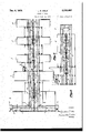
10 Sheets-Sheet 1 Filed Sept. 8, 1954.
Srm entor (ittorneg 3 1| i111 ill lxll ll| \ll IIIIIIllIuIII I 1O Sheets-Sheet 2 HU- I I II M O (Ittorneg 6, 1938. 1.. c. COLE MACHINE TOOL Filed Sept. 8, 1954 Dec. 6, 1938. L. c. COLE 2,139,403
MACHINE TOOL Filed Sept. 8,1954 10 Sheets-Sheet :5
3nnentor y m 4 all (lttomeg 1938- 1.. c. COLE 2,139,403.
MACHINE TOOL Filed Sept. 8, 1954 10 Sheets-Sheet 4 ((3a) M MrM Gttorneg L. c. COLE 2,139,403
MACHINE TOOL Filed Sept. 8, 1934 1o Sheets-Sheet 5 1938- L. c. COLE 2,139,403
MACHINE TOOL Filed Sept. 8, 1954 10 Sheets-Sheet 6 L. C. COLE MACHINE TOOL Filed Sept. 8, 1954 10 Sheets-Sheet 7 FIJIWKU INVENTOR ATTOR Y L. C. COLE MACHINE TOOL Dec. 6, 1938.
Filed Sept. 8, 1954 10 Sheets-Sheet 8 Z'mmntor (Ittorneg 6, 1938. L. cl COLE 2,139,403
MACHINE TOOL Filed Sept. 8, 1954 10 Sheets-Sheet 9 Snfientor I W C 3 6/ (Ittomeg Dec. 6, 1938. 1 c. COLE 2,139,403
MACHINE TOOL Filed Sept. 8, 1954 1o sheets-sheet 1o HEHD H50 GDNTROLLHI OF HJJJLL- 7'0 TOOL HL'HD FEED CONTR UIHS OFAF.
ZSnnentor (Ittomeg Patented Dec. 6, 1938 a V Application-September 8,1934, WNmIMI 1 M ,1sc1 iim. (Cite-4;) i Thisinvention relates to apparatus for' peroi 'Operatingmechanisms corresponding '"respecforminga number of desired operations on work "tively to the constructions shown in Figs. 2 and 3; pieces ina sequential manner. 9 a Fig. 7 is anend elevation of the machine series one objectoi theinvention is the provision of as viewed from the left of Fig. 1, showing the a method, and apparatus for carrying out such end turntable andthe'broaching machine; 1 5 method, for performing interrelated sequential Fig. il -is an end view 01 the machine series 'as operations in timedrelationship onanadvancing viewed from the right hand end at Fig. 3; line of workpieces, in which the"operatiorisare Fig.19is a top planview of one of the fixtures, carried outrapidly and in a very economical showing theworhWhich :it supports in dotted fiomannerh' j i lines; g Another object is the provision of a process and F18. 10 is a transversesection through the fixapparatus 'in which alternate work pieces are ture'and track at the index table; 4
moved in carrying fixtures out of the lineoi ad- QFig. 11 showsth'e gearing arrangement for ro'--v vance to opposite'sides of the-lineinto machines tating the fixture exactly 180 at the index table; 5 for performing operations requiring a "longer Fig. 12 is a diagrammatic showingof the guidtime than those machines or mechanisms in the ing control leversused at a transfer station; 1
line i e e i Fig. 13 is a sectional view through the feeding e Anotherbbject oi the invention is the provision screw and fixture guide; 1 i p of a series of mechanisms adapted forsuccessive Fig. 14 is a diagrammatic showing various eleopeifa'tions'on work piecesmounted in carrying ts of e co ol a operat n system by fixtures; feeding means being provided for movwhich the control of the starting and stopping ing the fixtures different amounts in accordance movements are eflected; i v with the distance between the successive stations, Fig. 15 ha diagrammatic showing of the elecsuch feeding means being of simple construction trical circuits controlled by the drum; 23 andadapted to move the fixtures simultaneously Fig; 16 is a diagrammaticshowing of the motor 25 the required distances. control connections; and F Another object of the invention is the pro- Fig. 17 is a diagrammatic view of auxiliary convision, in a series-of operatingmechanisms foltrolling circuits. I i "lowing one another and adapted for successive "Theinvention as herein set-forth is described, 130 operations on work pieces, of afcommon feed for purposes of illustration, as applied to the ,screw for the fixtures fwhich carrt the work machiningfof engine cylinder blocks, but it will pieces, together with means cooperating with the be apparentthat other forms ofwork pieces refeed screw for guiding the fixtures intheirproper quiring various machine operations may be opattitudes in the desired path of travel. erated upon in accordancewith the proeess'and "Another object of the invention is theproviby the apparatus herein set forth." Furthermore 3 sion of a series of mechanisms of the*character as herein described, the invention compriss'mareferred to, having controlmeans for starting and chines for breaching and drilling the work pieces, stopping thevarious operations in proper timed {but other types ofmachines adaptedfor cutting "relationship one with another and arrangedto "or otherwise operating upon the work maybe 10 carryout the various operations with a minimum employed in conjunction w t Orin placed 40 of lost time. t j f i I drilling orthebroaching machines.
Other objects and advantages will be apparent f Reierringunore particularly to Figs. 1 to 6 fromthe following description, the appended "inclusive,the series of machines or mechanisms claims and the accompanying drawings in starts with an indexing tabiestation designated which,--; v V generally by the letter A and" provided for -rotat- Figs; 1, 2 and 3 ,taken collectively show aside "ing an empty work carryingfixtureor holder that elevation of a series of mechanisms embedying hasbeenmoved backirom the end of the line so thepresentinvention for carrying outseeuential- ""as to bring the fixture into alignment with the 1y a number of difierent operations on a series series of advancing fixtures. The fixture is then of work pieces; a moved to "the loadingstation B,and asthe fixture 50 Fig. 4 shows a top plan view,partly in section remains stationary between feeding or advancto disclose the fixture feeding mechanism, 0! ing' steps, the operator has sufiiclent time to apone end of the series of mechanisms, this view "ply the work; such asthe engine cylinder block corresponding to the construction shown in Fig. 1; H), to a'fixture duringthe time following the po- 155 Figs. 5 and 6show top plan views of the series "sitioning of the*"fixtureat-the top of the index ing table at station A and before the fixture is advanced from station 3 to the broaching ma chine C.
The breaching machine is a mechanism for 5 carrying out surface broaching to machine the cylinder banks, the cutting or bnoaching of the work taking place in a line transverse to the line of the machine series. as more fully set forth in my prior applicatim for Letters Patent, Serial 10 No. 714.044 for Machine tool, filed March 5, i934. Afterthebroachingofthecylinderbanks has been completed at station 0, the fixture, carrying the work with it, is moved .-a further step to station 1). The operation at station D is, for ex- 16' ample, a rough boring operatim of the'cylinders. .IThls operation requires somewhat longer than f the operations carried out at station C and some of the following stations,and to provide a small minimum time between feeding steps of the whole series of fixtures, successive fixtures adto stationD are moved laterallyto opposite sidesof the line of advance into two separate boring machines D and D', one fixture, for example moving out to machine D the next fixture moving out to machine D and a following fixture moving out to machine D, the fixture previously subplied tom'achine D. having Just previously moved back into-the'line of advancing fixtures and again resuming its forward movement along the line.
After leaving the station D a fixture travels on to an idle station E which may be provided between station ,D andv the next machining station I. At station I", as at station D, the time for carrying out the desired machining operation may becomparatively long, and as herein shown, two similar operating mechanisms F and l" are provided at opposite sides of the line and adapted to receive alternate fixtures from the advancing line. The machines I! and I" may drill the valve guides and the P l rod holes of the engine cylinder block.
After leaving the station F, the fixture is moved ahead to a turn table station G, where it is rotated about a vertical axis through 90 degrees so that the cylinder rows which previously extended transversely of the line of advance will be so moved as to extend parallel to the line of advance. In this latter .position, the work,-carried by thefixture, is moved another feeding step to station H and it is there operated on by drill mechanism which can, for example, drill the valve throats. 'I he opposing drill banks at station H incline downwardly and inwardly towards the line of advance instead of inclining in planes parallel to the line of advance as at stations D and 1". l
The next. feedingv step takes the fixture and thework to station .I, which as herein shown is another drill mechanism adapted to drill holes in the cylinder banks. The next feedingstep carries the work to station J, another drilling mechanism, for chamfering the holesin the cylinder banks. A further step carries the work to station K for chamfering the, ends of the cylinder bores. The next station is station'L, where holes are drilled in the top of the cylinder block. This is followed by station), another turn table station, where the fixture is rotated again through 90 degrees to bring it back to its original attitude with' the cylinder rows extending transversely to the line ofhdvance. The next stationis an idle or unloading station N, and the last advancing step takesthe fixture. to station where it is indexed by moving it about a line parallel to the line of advance, thus inverting the fixture and moving it into the line of return which, as herein shown, is below the line of advance. The work is removed from the fixture at stations N or 0 before the indexing or rotating movement of the fixture takes place.
After the fixture is inverted, at the end of the line, it is then moved back rapidly to the head of -the,line and then moved up into the line of advande. Another workpiece is then secured to it and moved up into the line of advance.
It will be understood that in carrying out the various machining or cutting operations on the work as the work passes through the line of mechanisms, the work is fed forwardly predetermined distances step by step, the work remaining fixed while being operated upon by the mechanismsandtravelling from one mechanism to a succeeding mechanism so that when the work reaches the end of the line a large number of operations have been completed, and the work can then be removed and other operations carried out, if desired, in another. line of mechanism adaptedfor the. particular operations to be subsequently performed;
I One of the operating mechanisms of the seriesv carries, out .its intended function on one work piece atv that location at the same time the other imechanismsare also carrying out their intended .been illustrated in' Eigs. 9 and 10, as indicated generally by reference numeral 9, are preferably square as viewed from above. Each comprises a vertical wall portion ii anda bottom portion I2 on which the cylinder .block or other work is clamped in a predetermined position, as by means of the holding clamps .or arms it.
At a plurality of spaced points, preferably at diagonally. 'bl posite corners of the fixture, the vertical walls i I. are socketed or recessed as indicated at it, the sockets serving as locating points .by'means of which the fixtures are exactly and accuratelylocated in a machine after being moved into approximate position in the machine by. the feedingmeans. Each machine has a pair of studs on'a pressure block which is moved down after the fixture is approximately located sothat the studs enter the sockets ll of the fixture and cooperate therewith to accurately position the fixture with respect to the cutting tools of the machine.
Adjacent each corner and near the lower portion of the fixture are rollers I adapted to operate along carrying tracks it, see Fig. during the. returning movement of the fixtures when they areinverted. lLEach fixture is also provided with four downward projections that extend down from the fixture base, in the form of cylindrical pins or rings I8, is, and ii. These rings are rotatably mounted in the bottom wall of the fixture-and'serve to guide the fixture in a straight pathduring its advancing movement and to cooperate with a feeding screw which produces the desired feeding movements.
The feeding screw; which is generally designated by the numeral 23, comprises a number of sections. The first section 24 is adapted to move the fixture from the indexing table at the head of the line to the idle station B as the feed screw is rotated a predetermined number of revolutions, the machine as illustrated being adapted for nine revolutions of the feeding screw to ad-, vance a fixture from one stopping point to the moved up into position by the indexing table at station A. Nine revolutions of the screw section 24 will then carry the fixture ahead'to the position shown in dotted lines in Fig. 4 at station B. After a predetermined time interval, the
screw shaft will again rotate nine more revolutions thus moving the fixture from station 13 to the center of station C. The thread spacing of screw section 24, as shown in Fig. 4, is such that the two pins l9 and I8 are simultaneously en-.
gaged with the threads. Thedistance between the pins I 8 and I9may for example be 36","and. the threads on the screw section 24 may have a pitch of 6" so that'the pin I9 is first engaged alone and after the fixture is'advanced from the indexing table the pin it is also picked up by the threadrof the screw. I
The threads on the screw section 24 terminate at sucha point as to -leave the 'fixture centered at station C afterthe rear pin lfipasses beyond effective propelling engagement with the. thread. This bringsthe forward pin [3 of the fixture into such position that after a predetermined angular travelof th'e screw of about 90 degrees, the thread on the nextsection 25 of the screw will be brought into propelling engagement with pin [9 and move the fixture through another advancing step. a
The screw sections, which are connected together for simultaneous rotation, are rotatably carried in a series of bearings at the ends of the sections. The forward end of the first screw section and the rear end of the last section, and likewise the outer ends of the auxiliary transverse screwsections, are also carried in a semicylindrical bearing" shell 25 which engages the outer portions of the threads on the screw as shown in Fig. 13, leaving the upper portion of the screw exposed througha central slot 21 in the bed of the fixture support. "This slot 21 which extends the length of the various machines and which is formed by the two spaced guide plate portions 28 forms a guide for'the rotatable pins I8 and I9 of the fixture. In Figs. 4, 5, and 6 the machines are illustrated with the plate portions removed except at one point at station D, for purposes of better illustration; The side pins 20 and 2| operate freely between the surfaces 29, which extend lengthwise of the series and at opposite sides of the fixture bed on which the bottom of the fixture is slidable. The fixture is therefore maintained in its desired attitude'as it is moved forwardly by the feed screw.
Before the fixture is moved from station C, and while the screw is stationary, the desired machining operation is carried out at station C. The mechanism at this station is a broaching machine, as previously mentioned, having broaching tools 33 "carried by a suitable ram tudinal movement.
which operates transversely of the line of advance and cuts the cylinder bank surfaces simultaneously, this operation being carried out comparatively rapidly and requiring only a fractional part of a minute even for a large surface such as a cylinder block. It will be understood that when the fixture is first moved tothe position C by the screw section 24, and at the end of the feeding movement, the vertically movable pressure block 32 of the broaching mechanism C will descend and bring the locating pins provided thereon into the locating sockets 14 of the fixture, whichare suitably: tapered to facilitate the engagement of the locating pins, so as to exactly position thefixture'at this station. The broach then moves across the work, performing its intended operation, and returns, and during V and groove device 34 forming .a joint which insures simultaneous rotationatboth sections. The
rear or runoff end of thesection'24 is journalled in a suitable bearing 35 which is provided below the path of the pins l8 and IQ of the fixtures and which definitely holds the section against longi- On the opposite side of coupling 34 is a second bearing 35' which rotatably supports the forward end of section 25 without,
however, holding this end against longitudinal movement, as it is only the run off or rear end of each screw section that is so held in order to provide for expansion eifects. Adjacent the bearing 35 is a bevel gear 36 of such size as not to project into thepath oftravel of the fixture pins, this bevel gear meshing with a driving pinion 31 carried on a shaft 38 which extends out angularly as shown in Fig. 4 for driving connection with an electric motor 39. Similar motors 40, 4| and 42, and similar driving connections of the screw or feeding shaft are provided at spaced points along the screw so that the entire screw will be driven at a number of spaced points and the driving force and torque tendencies thus distributed.
The feeding screw 25 moves the fixture a much greater distance than the first and second feeding steps, the distance from the center of station C to the center of station D being comparatively long. The pitch of the threads on the screw section 25 is much greater than the pitch of the threads on section 24, so that nine turns of the shaft willadvance "the fixture the comparatively long distance from station C to station D, the pitch being properly coordinated with the distance through which the fixture is to travel from one station to the next. I The pitch of the threads in the section 25 may for example be 12" so that thespacing between the pins I8 and 59 on the fixture is a multiple of the thread pitch in. order that the threads of the screw section simultaneously operate in propelling the two pins I8 and IQ of the fixture during its advancing movement up to the station D. The distance between threads of section 25, and also between the threads of all the other sections of the feeding screw is considerably greater than the diameterof the pins l8 and IS on the fixtures.
When a fixture reaches station D, the main feedscrew stops, leaving the fixture in the center of the station, but free of lateral restraint, as the side pins 20 and 2| are now positioned opposite 15 the slots 44 which extend transversely of the line of advance, and as the guide plates 2! are interrupted directly opposite the pins I8 and II at the stopping position of the fixture. The fixture is thus free to be moved laterally to either side of the line. The fixture is moved out of the line of advance to the machine or mechanism D by means of an auxiliary feed screw ll, similar in construction to the screw section 28. The threads on this section I, however, with the screw section in its normal position, terminate outwardly beyond the path of the side pin 2|, and in order for the pin ii to be picked up by the threads on this section ll, the latter is moved endwise toward the fixture the proper amount under the control of a fiuid pressure operated plunger ll, the screw section 45 then being rotated by an electric motor 41 to move the fixture laterally into the machine B. when the pin 2| of the fixture has been moved beyond the end of the threads on the auxiliary screw section I the fixture is approximately positioned in the desired relationship with respect to mechanism D. However, to accurately and exactly position the fixture before the cutting operation on the work starts, the boring machine I) is provided with a locating head carrying locating pins engageable with the locating holes ll of the fixture. This head first descends and first positions and then securely holds the fixture with respect to the fixture supporting bed. After this has been accomplished the boring tools II are brought into eifective engagement with the work. Suitable electric motors B2 are provided for operating the boring tools.
After the boring operation at machine D has been completed the positioning head it rises, freeing the fixture so that the fixture can be moved back to the line of advance, the movement back to the line of advance being efiected by the auxiliary screw 48 which is first moved endwise toward the fixture so as to bring the end of the screw threads below the fixture pin II, this movement being effected by the fiuid pressure cylinder ll. The screw is then rotated in a reverse direction by the motor so as to move the fixture back to the lme of advance. It will reach that position when the pin II has been moved to the end of the screw thread on the auxiliary section 48 while the latter is still in its outermost position.
A similar machine D is provided at the opposite side of the line, and fixtures can be moved to and from the machine l) in the same manner as they are moved to and from the machine 1'). One fixture is moved to machine I). the next to machine D', etc., successive fixtures being moved to opposite sides of the line. If there is a time interval of 36 seconds between successive feeding movements of the fixtures along their line of advance, a fixture may remain in the machine D, for example, twice as long for thewlonger operation taking place in that machine, before being returned again to the line of advance. The operation of the other faster. machines in the line is therefore not slowed up and a very high output can therefore be obtained.
For guiding the fixtures as they move into the station D at a time when they are not continuously guided in their advancing movements by the slots or guide surfaces along which the fixtures operate, a pair of pivoted arms 64 and I! are provided at each side of the line of advance, see Figs. 4 and 12. These arms are rotatable through 90 degrees into the dotted line position shown in Fig. 12 so that the rotatable rollers Ii carried by the arms, after serving to guide the sides of the fixtures into the station D (or from the station D to the next succeeding station) will be effective in guiding the fixtures laterally to machines D and D. The arms are automatically operated at the proper time in the sequence of operations by fluid pressure means, or the like, as will be more fully described.
After'the boring operation has been completed on the work in either machine D or I), the work is moved back to the line of advance and the next feeding movement of the niain feeding screw propels the fixture under the action of the screw section I to the idle station E, another feeding operation advancing the fixture under the control of screw section II to station I". At station F and at opposite sides of the line of travel, as previously mentioned, are the mechanisms F and I" to which alternate fixtures are supplied in the same manner as they are supplied to the machines D and D'. The fixtures are alternately supplied from the machines I" and F back to the line of advance and then moved forwardly by the screw section 5| to a turn table station G. Here the fixture rests on a table II which is slotted annularly as indicated at 60 for the reception of the pins ll, i8, 20 and II as the fixture is rotated. The fixture is engaged by a turning head II which first descends under the action of a fiuid pressure cylinder 82 so as to bring its locating pins into engagement with the cating holes ll of the fixture. The head II is then rotated 90 degrees about a vertical axis so that the fixtures are then arranged as shown in dotted lines in Fig. 5. The head Ii then rises, freeing the fixture for further forward movement under the control of the feed screw. The screw section I! then moves the fixture forward to station H. The drill axis at this station inclines upwardly and outwardly away from the line of advance, the mechanism H being comparatively long in a direction transverse to the line of fixture movement. By turning the work before it is moved to station H,'the mechanism B. may be arranged in the position as shown so as to reduce the length of the line of machines.
The work is held in the exact position desired in the machine H, by a vertically movable pressure or locating head 85 which descends before the drilling operation is started, the head 65 having locating pins .engageable with the locating sockets ll of the fixture. The head is of course released by upward movement thereof at the proper time after the drilling operation has been completed to free the fixture for further advancing movement.
After leaving the machine H, the feed screw section ll moves the fixture to station I, and in a similar manner the screw sections 01, 68 and 69 move the fixtures to successivedrilling machines J, K and L. Section II of the screw takes the work from station L to another turn table station which is similar to the turn table station G, but which rotates the fixture back to its original position so that the screw section II moves the fixtures with the work positioned in such a way that therows of cylinders extend transversely of the line of advance. The section II of the screw moves the work to the unloading station where the clamping or holding arms retaining the work in the fixture are loosened and the work removed. The fixture is then automatically moved on to the rotatable indexing table at station 0, being 'moved beyond the end of the threads on the feeding saw; he in exi g" table i then rotated so as to invert; the fixture and dumpthe chipsfrom the fixture, bringing the fixture into theline of return as; shown in; theglower portion ofFig. 10.
The fixture is then returned tothehead of, the
line through a, passage provided inthev various a connected machine ,frames -andtfixture support r ing bed, sections provided betweenadjacent T-he indexing movement ofa fixture as it ismoved o at station O is always clockwise as viewedin Fig 8, bringing the fixture to its invertedposition and bringing the thread1 fragment of the; fixture into engagement with thereturn screw 11. l At the it ;head end of theline as to position the fixture on the indexing table atstatiomA when the thread fragment on the fixturemoves off of the, return screw; ,When the fixture isimoved up by the in- The comparatively long distance between succes head endof the line the fixture is indexed in the opposite direction,uthat is clockwise as viewed in f ;Fig. '7 The threads on the return screw 11 preferably terminate atsuch a, point: adjacent the dexing table atstationA itis brought into such a positiomasgshown in Fig."f4, that the pin [9 is somewhat to the right of ,the end of thethread on the screw section 24, which, however, is stopped at t that time in such positiontas to permit pin l9 to move to aposition directly. above the screw axis.
, sive screwthreadsof the screw with respect to the diameter of thefixture pin readily permits this.- o a The feeding screwis stopped automatically as will 40,
be further described so as to requireaboutQO degrees movement to pick. up the fixture, and the relationship between the threadsofradjacent'sections: of the, advancing screw is also such that ;abut,,90-degrees movement of the screwis required beforethe 1,-forwardupin l9,of anya.fixture is pickedup at thestart of a feedingoperation. As will be apparent fromcFigs."1 to fipthe fixturew carrying supports 1 or-bedsections'are =detachably ,boltedto the machine tools or operating mechanisms, withwhichtthey are associatedsothat anyfl mechanism can-beremovedfrom the line or series .for repair purposesor the like; the sectionalrchar- 1 acterpfpthe feed screw permitting theremoval of:
1 any machine tool withoutdisturbing the positions 10f; the othermachinertobls or the other parts of t the feed screw.
Thefixtures are m o vedexactly 180 degrees in their indexing or turning movements at anend of the. lines Thismovement isigaccomplishedwby an: electric motor, which drives} a worm operating worm'gear 80, see Figs. ll andl'l. The worm gear w :80 is fixed to a gear 8| which makespne complete rotationnbefore the motor 1 is; automatically; stopped. "The grooveslin the-gear 8| are engaged by teeth in a-gear 82 which mesh'eswith a gear 83 fixed to the index table. ='2'l', :-degrees rotation m s t n o t s c0115 o e-n switches 4" gear Bl moves the geart83,-and consequently the indextable exactly 180 degrees 1 The remaining 90 degrees movement ofgear-Bl mereljyholds the gear 83 exactly positionedas the grooves extend annularly in the'gear 8| ,forc'one quarterof its a circumference, as shown in Fig. 11.
At the beginningof eachcycle of operations, the fixturesare stationaryv one on e'achlongitudinal station except on the unloading index table.
- operator has just finished trolling; operator at ;of'the,line.
'tion for each cycle; l c i D snar One fixture-is on the bottomofthe loading; index table; ,All the tool heads are. up,
their locating pins having 3 been withdrawn-and having, at thelimit of their upward movements, closed electrical contacts or switches whichautomatically. initiatea new cycle of operations. The
head of the line.
master starting switch 86 shown in Fig. 15. From then on each cycle is initiated automatically unless the operationisstoppedby the emergency switch Blor by the tripping of overload relays. The emergency switch fllhis operatedbya cable which is operated within easyreach of theconany point along the length The apparatus illustrated in Figs. 15, 16 and 17 maybe used forthe automatic control of the various sequentialoperations. This apparatus A fixtu reis on eacho f the two cross index sections loading a bloclr at the includes a master controlling drum 89 which carries cams 90, 9| sass-s4, 95,- 96, 91,98, 99, I00
and IBI. ,Fig. 15 shows thevarious cams devel oped in a single planethroughout the 360 degrees extent of the drum. The length of each cam represents the length, of angular movement in which a contact is held closed for performing its desired function. r, The drum 89 is driven as shown in, Fig. 14 through a differential gear drive I02 from the screw 23 and alsothrough a differential gear drive connection N13 to the, return complete revolu- I screwfll the drum making one The stopping of the longitudinal, index, screw 23 at the end of nine, revolutions is controlled by cam 9|} opening itscontact. The drum is being turned up ,to this point because the master switch 86.is closed and a circuit is completed across the line terminals lM through the closed overload relays H15 and through the, energizing coil I05 which energizes low voltage relay I06, which functions-to short -cirouitrthe starting switch 86 after the latter has been'closed. This energizes one side of the; various contactspperated by the variouswcams; The,contact operated by cam 9D is therefore closed, completing the through the variousswitches 101, which are anj-tomatically closed by the machine heads of the :various machines'whenin their raised positions,
circuit energizing the coils J08. [09,110, andwlll, thus closingtheswitches .l 055, to l H inclusive toenergize coil H2. Coil l l2 being energized closes switch I I21, thus ycompleting 1 a circuit through the contactvof ,cam fll The switch I I2 ener- 1 gizes the, four screw: ,driving motors,.39-, to 42 simultaneously, gsee, Fig;;1,l,6)thus causing the drum to rotate, as it is connected to :the screw.
, After thescremhas made about eight revolua tions, and before the cam 90 opens its contact to stop the motors, the cam SH opens its contact,
if energizing coil I I3 whichhad been short circuited ;by closed switch ,I I2. Energizing coil H3, closes the switch Il3;shown in;Fig. 17 in an auxiliary circuit which energizescoils land 5., The
,aboye mentioned, eam 92 closes, its contact, en-
erglzingycoils H1, H8, H9 and 120 :thus closing shunt resistance I21 across each" motor arma-. ture which causes the motors to run more slowly contacts ll l' llB H9 and l2llf, cutting in a' until such time as the switch II! is opened by opening the contact of cam It at the end of nine revolutions of the index screwpdynamic braking being applied to the motors which 'stop within the allowableovertravel'of about sixty degrees of the screw.
When thescrew'stops,'thedrum also stops for -a short period (until it is again-driven by the operation of-the return "screw 11 When the drum comes to a stop, the'cam "keeps its contact closed, and a timelimit' relay TL-I'is energized which. however, is so timed as to close its contact about one second or so after the drum has stopped." Closing of the contact of this time limit relay energizes coil III, closing switchiu, thus energizing coil I23; Theenersimtlon of the coil llt cioses switch III (see dex motor I21.
Fig. 18), starting the motor I: A similar arrdigement at the same time energizes coil Ill closing switch I2l' thus energising coil I28, closing switch I28 and starting'the'other rotary in- I the bottom and bringing the fixture which was at the bottom-at the head of the lineup to the top to lie loaded again. Suitable feed limit switches II! and I" are employedto controlthe stop s oi the index motors.
At the same time the rotary index motions take place. the closed contact of cam 82 has also energised electric solenoid coils in and m. first of these is attached to a commercial air or hydraulic control valve (see Fig; 14) of any suitable character and shifts its piston in a direction to let air or other fluid under pressure enter the line ISL-causing thevarious locating pins III to descend and enter the hold provided in the flxtures to'exactly locate the fixtures in their proper positions for machining the work piece which they carry. Atthe end of'the lineIsl is a pilot line I supplying fluid to pilot valve I81 and reset valve III. The latter pilot valve mm posltioii to letfluid enter the line m.-
operating a suitable valve. to a position to let fluid enter 11mm. the rotary fluid valve III to turn'ilil' degrees, rotating a shaft Iflthrough 180 degrees through an eccentric connection, moving the broachsaddle I down-- wardly. "fhebro'ach saddle carries locating pins locatestheflxtureinitsproperplaoer 1 The line Ill aho supplies fluid to a cylinder I" on the turn tabieat station ll, thus lowering the head I which isprovided with locating pins which enter the holes provided in the fixture engageable with the holes in theflxture. At the end of the stroke of the piston I" a projecting member I unbslances a control valve in, Oil! ing its piston to move to such so as'to cause the rotary head I" to turn exactlya 90 degrees. I SImilarioperations take place at the turntable of station G.
Solenoid m which was also operated with solenoid It! supplies fluid from asupp v Pip I The :various' coils above men- Thef position as to let fluidenter line IlI'andoperate a'rotary motors I21 and I24, closes'its contact, but no current is supplied to the return screw motors until the rotary index operations have been completely stopped and the rotary limit switch I30 has closed a circuit through the time limit relay TLI.- The time limit relay operates after a second or so delay, to then start the return screw motor, consequently causing the drum to rotate. The time limit relay IL-2 is inserted in this circuit for safety to insure complete engagement of a fixture with the return screw before the return screw starts moving. The return screw now'propels the flxture towards the head of the line. The broach at this time-is also performing its cutting operation under the control of its self-contained fluid pressure operated control system.-
, The locating pins m of the various'machine tools have moved their respective fixtures to their proper positions after stopping the index screw. These pins are attached to pistons I which have extensions III which open and close double limit switches III and I". With the pins in their lowered positions, the extensions I" each opens a switch"! and closes a switch I". The closing of all the contacts or switches I60, as indicated in Fig. 17, operates the tool heads or cut ting devices of the various machines, so that all of the drilling operations at stations'H, I, J, K, and L start simultaneously.
Shortly before the cam Oil opens its contact, cam DI which controls the starting of the fixtures in both directions at stations D and F', closes its contact but no current is supplied to the crossindex motors I82 and III until the cross index levers II and I! have each closed a circuit through a limit switch I". The closing of the limit switches I energizes the cross-index motors it! 1 and I so that the cross-index screws will pick up the fixtures at stations D and F and propel them. to the machines D and 1". Towards the .end ofits travel, the fixtures are slowed down,
since the motors are slowed down at this time, so
that when the flxture disengages itself from the transverse feed screw section it stops at the proper place. After it hasdisengaged itself from the screw,,limit switches I" and I open their contacts and dynamic braking is applied to stop the fixtures within 60 degreesovertravel of'the screw. :The limitswitches I t! and I68, together with a number of additional limit switches are provided in the boxes I and operated in proper timed sequence by movable controllers which are driven from the motors I" and I I.
, Shortly after the flxture leaves the center of station D on its outward travel movement to D the reverse limit switch I10, operated in timed relation with'switches I01 and Isl is closed, but no reversingof the motors takes place as the limit relay TL-4 (which is controlled by a limit switch controlled coil TL-l') is kept open. The motors'whichoperate the lateral screw sections come to rest by openingrof the limit switch I6? at the same time the reverse limit switch contact III is closed; and after cam opens its Contact to cut its current completely off, TL-4 closes, thus establishing the reverse circuit for the motors. At the next cycle the motors I62 and I63 :will start up in the reverse direction and thus move theflxtures back to the line of advance.
the work. The solenoid I14 similarly operates to move the plungers I100: machines D and F downwardly and bring the locating pins I10 of the machines D and F into engagement with the working fixtures carried in those machines. The pistons I10 also carry extensions similar to the pistons I30" of the single drilling machines, these extensions operating switches I and III. The closing of all the contacts ill of the machines D and F when the plungers, I10 are loweredr energizes the tool head motors, thus causing the operation of the drills. Lowering of the tool heads opens switches I04- deenergizing solenoid I14.
While the drum 00 is still turning, driven by the return screw, the cam 00 opens its contact, deenergizing solenoids I14 and I15. Subsequently cam I00 closes its contact, but no circuit is established at that. instant. The machining operations at stations D and F have been meanwhile completed and the tool heads returned to their upper positions, closing limit switches I04. This energizes solenoid coil I00 to raise the locating pins and the head which carries them. Solenoid I operates its valve to supply fluid to line I06, raising the various pistons and the pin hold ing heads of machines D and 1".
Raising of the locating pin heads of machines I) and F closes contacts or switches I00 and opens contacts I00. The closing of the contacts I00, with the cam 01 closing its contact supplies current through the time limit relays I00 and IOI establishing circuits to energize the crosstraverse motors I02 and I00, and as the reverse circuit was established atthe previous cycle the motors are started so as to move the fixtures from machines D and I" back to the line of advance. Toward the end of its travel the motor slows down the. same way as previously described in the opposing machines D and F. After the fixture leaves the lateral feed screw section, relay switches I04 and I05 open and stop, the motors by dynamic braking before 00 degrees over-travel of the screw.-
Shortly after the fixtures leave the stations D and Fl traveling towards the center or line, of advance, limit switches l91and I00 are automatically opened to prevent the solenoid I00 and solenoid I05 from being energized when the cam IOI closes. At the same time, limit switches I94 and I00 are closed, partly establishing the outward feeding circuit for the next cycle, but no movement takes place as the time relay TL--1 and IL-0 are kept open until cam 01 has opened its contact. Then TL--1 and TL-0 are closed.
to establish the outward feeding circuit for the next cycle. I
The solenoid I00 operatesthe feeding screws for the machines D and I" longitudinally at the proper time, the circuit for the motors which turn these screws being established when cam I0I recioses its contact. Reverse limit switches 200, IN 202 .and 000 are also-closed to short-circuit time limit relay coil 204 which "operates the time limit relayTL-I I, and which closes after a second or so of delay to energize solenoid I33. This operates the fluid pressure valve to supply fluid to the line 200 which moves the fixture guiding levers so as to guide the fixtures in their line of advance through the machine series. When these levers come into their longitudinal position they automatically close limit switches 206 which are in circuit in series with the switches I01 shown at the upper part of Fig. 15.
When the various "tool heads of the drilling machines H to L inclusive have completed their operations and return to their upper position they each close limit switches 200, provided in series with contact of the cam 00; so that when all of the machines have stopped, thev solenoid coil I02 is energized and its control valve is shifted to supply fluid to line 200 thus causing the pistons I00 to move upwardly, withdrawin the locating pins from the fixtures. At the end of the upward movements of the various pistons, their extensions open contacts I00 and close contacts I00, thus partly establishing the circuit for longitudinal indexing.
. The broach in the meantime has finished its cutting stroke, and its trip 2I0 has shifted the pilot valve I01 to the right, causing fluid to enter the line I09, reversing the operation of the valve I40 and reversing the operation of the valve I42 so as to move the broach saddle throughthe eccentric arrangement in an upward direction. The broach proper returns to its original position by its own operating unit. The piston of the resetting valve III is moved upward toward its original position by the supply fluid through the line 100. At this time the return screw comes to a stop, having been previously slowed down by the cams 04 and 00 which control circuits for cutting in resistances for the control, of the speed of the return screw at the end ofits operating movement. Shortly after the fixture leaves the return screw, the cam 00 opens its contact to stop the return screw motors III and ii! and apply dynamic braking. At the same time cam 03 opens its contact, cams 00 and II close their contacts, and cams 00 and Ill closetheir contacts. The closing of these contacts initiates a new cycle. In this new cycle, after the longitudinal indexing of the fixtures has taken place, the fixtures will move from the center of stations D and F to the machines D and F instead of moving to machines D and F as they did in the previous cycles. After the fixtures on these stations come to rest, solenoid coils I90 and I05 will be energized by closing contact of cam I0l, and the forward switches I01 and I00. The solenoid coil I00 operates one side of the solenoid shown in Fig. 14,,shifting its piston so as to let fluid enter the line in order to move the transverse feed screw sections D and F outwardly so that the screws may pick up the fixturein the machines D and F in their feeding movement. The solenoid I00 operates to supply fluid to the line which lowers the pistons I10 provided on the machines D and F so that the locating pins on the heads of these machines are engaged with the holes in the fixtures.
After, the completion of the operations of machines D and F the tool heads of those machines move up and close limit switches I04 in series with the contact of cam I00, energizingsolenoid coil I14 operating the fiuid control valve to supply fluid to move the pistons I10 of machines D and F 'upwardlythus withdrawing the locating pinsjirom'the fixtures inthesemaclnnes.
8 s,iss,sos
After the reverse cross-indexing from the machines D and 1'', limit switches Ill and III are closed, energizing solenoid III The coil of this solenoid shifts the piston of the solenoid valve s tosupplyfiuidinsuchamannerastocauseendwise movement of the screws of machines D and I so that they will be able topick up the fixtures for cross indexing when the next cycle starts.
Thelimit switches (III, III, I'll, ill, ltletc.)
II are all operated at their proper times in the severalswitchboxes ltlofthemachinesb and D and IF and I" and properly interrelate the various feeding and operating movements of these machines with the other machines 'of the II series. Suitable auxiliary circuits, shown diagrarnamtically in Fig. 17, are interposed as required by the various operated mechanisms shown in Fig. 15, The controlled devices such as the motors, the motor resistances, switchu,
Q etc.. are shown inl'ig. 16.
While the method herein described, and the form of apparatus forcarrying this method into efi'ect. constitute preferred embodiments of the invention. it is to be understood that the inmade in either without departing from the scope of the invention which is definedv in the appended claims.
80 What is claimed is:
1. Apparatus of the character described comprising a series of mechanisms spaced diiferent distances apart and one following another for successive operations on work pieces, work car- 35 rying fixtures, and feeding means for moving said fixtures predetermined amounts to advance them through said mechanisms, said feeding means comprising a rotatable device extending through a number ofsaid mechanisms and having threads socngageablewiththe fixturesand arranged to advance a fixture 'dificrent distances in accordance with the difierent spacings of said mechanisms at difierent locations along said device for a given number of revolutions of said device. 4 2. Apparatus of the character described comprising a series of mechanisms spaced different distances apart and one following another for successive operations on work pieces, and feeding means for moving said work pieces predetermined amoimts to advance them through said mechanisms, said feeding means comprising a rotatable device extending through a number of said mechanisms and having threadsof difierent lead at different points along the length of said a device for simultaneously advancing different work pieces diiferent amounts in accordance with the difierent spacings of said mechanisms. and means for intermittently operating said feeding means a predetermined number of revolutions to advance the work pieces through said .diifrent amounts.
3. Apparatus oi the character described comprising a series of spaced different distances apart and adapted for-successive 'operations on work pieces, work carying fixtures. and
feeding means for moving said fixtures predetermined amounts in a step by step manner to advance the fixtures to and through said mechanisms, said feeding means comprising a rotatable shaft extending through a number of said mechanisms and having threads of difierent lead with the lead of thethreads coordinated with the disother, said feeding means comprising a threaded shaft formed-of longitudinally connected sections,
the threads of the different sections having leads cordinated with the distance between mecha- 5. Apparatus of the character described comprising a series of mechanisms one following another and adapted for successive'operations on work pieces, work carrying fixtures, and feeding means for moving said fixtures through said mechanisms and from one mechanism to the next, said feeding means comprising screw sections engageable with the fixtureathe threads of each section being spaced such a common distance from the threads of an adjacent section as to advance a fixture to a position free of engagement therewith before the fixture is engaged bythe succeeding section, whereby a dwell period is provided for the fixtures at the end of each advancing step.
6. Apparatus of the character described comprising a series of mechanisms one following another and adapted for successive operations on work pieces, work carrying fixtures, and feeding means for moving said fixtures predetermined amounts to advance. them through said mechanisms and from one mechanism to another, said feeding-means comprising a series of screw sections having threads of different lead engageable with the fixtures, supporting means for said sections engaging the outer sides of the threads at 0 one side. of the sections, and means for driving said sections at different points along the length of said feeding means.
'I. In an apparatus of the character described,
work carrying fixtures, and feeding means for moving said fixtures predetermined distances, said feeding means comprising screw sections, said work carrying fixtures each having a plurality of screw engaging projections, the threads section being spaced from the threads of anadjacent section a distance slightly greater than the distance between the projections on a fixture, so that the fixture is not engaged by a following section until after the fixture is moved completely out of engagement with the preceding section.
- 8. In a series of mechanisms adapted for successive operations on work pieces, work carrying fixtures each having a pair of screw engaging projections,-and feeding means for said fixtures adapted to" advance them through said mechanisms andg-from one mechanism to another in steps of different length, said feeding means comprising screw sections having threads of different lead in accordance with the required step lengths but each'section adapted for simultaneous driving engagement with the said pair of I. Apparatusfor the character described coma series of mechanisms one following another and adapted for succusive operations on work pieces, work carrying fixtures, operable h said mechanisms, and a turn table in said series provided between a pair of adjacent mechanisms and adapted to rotate'a fixture a predetermined angular amount when it reaches the turn table, feeding means for advancing said fixtures step by step through said mechanisms to and from said turn table, each of said fixtures having means cooperatively engaged by said feeding means in either position of advance of the fixture.
10. Apparatus of the character described comprising a series of mechanisms one following an.- other and adapted for successive operations on work pieces, work carrying fixtures, a turn table in said series provided between a pair of adjacent mechanisms and adapted to rotate each fixture as it reaches the turn table station, and feeding means for advancing the fixtures step by step from one mechanism to another and for advancing the fixtures to and from said turn table, each fixture having means cooperatively engaging said feeding means for advancing the fixture to said turn table and having additional means cooperatively engaging said feeding means for advancing the fixture from said turn table.
11. Apparatus of the character described comprising a series of mechanisms one following another and adapted for successive operations on work pieces, work carrying fixtures, a turn table in said series provided between a pair of adjacent mechanisms-for rotating a fixture supplied thereto on a vertical axis through a predetermined angular amount, and a common feed screw engageable with said fixtures for advancing the fixtures step by step from one mechanism to another and to and from said turn table,
'each fixture having a projection symmetrically located between its sides and engaged by said screw as the fixture is advanced to the turn table and having an additional projection symmetrically located between its sides as the fixture leaves the turn table and engaged by said screw.
12. Apparatus of the character described comprising a series of mechanisms one following another and adapted to perform different operations on work pieces passing through such series, means for feeding a series of similar work pieces step by step in a common line of advance through said series, additional mechanisms disposed laterally on opposite sides of said series, and means.
for moving successive work pieces out of the common line of advance to-opposite sides of said series to said additional mechanisms and for returning the. work pieces from said additional mechanisms back to the line of advance.
13. Apparatus of the character described comprising a series of mechanisms one following an-.
otherand adapted to perform different operations on work pieces passing through suchseries, work carrying fixtures, means for feeding said fixtures step by step through said series from one mechanism to a following mechanism, a transfer station provided in said series, a plurality of additional mechanisms disposed laterally of a common point of said series at said transfer station, and means operated intimed relation with said feeding means for moving successive fixtures out of a common line of advance to different laterally disposed mechanisms and for returning the laterally moved fixtures back to the line of advance.
14. Apparatus of the character described comprising a series of mechanisms varying in size and one following another in succession for operation on workpieces and adapted for broaching and drilling operations at diflerent stations along the series, work carrying fixtures, and a feed screw for moving different fixtures different amounts coordinated with the 'spacing'between successive stations.
15. Apparatus of the character described com prising a series of mechanisms one following another and adapted for successive operations on work. pieces, work carrying fixtures each having screw engaging projections, a feed screw engageable with said projections, pivotally supported guide means engageable with two lateral sides of a fixture for maintaining the fixture in a predetermined attitude as it is moved by said feed screw, andmeans for rotating said guide means a predetermined amount so that the guide the time of operation is longer than the time between said feeding steps.
17. The method of machining work pieces comprising feeding the work pieces in carrying fixtures step by step along a series of machine tools in which different successive machining operations are 'carried out in the interval between successive feeding steps, and alternately shunting the successive fixtures and work pieces temporarily out of the line of feed and into alternate similar machine tools in which the time of operation is longer than the time between said feeding steps. v p
18. The method of similarly machining work pieces comprising feeding the work pieces in carrying fixtures step by step along a series of machine tools in which different successive machining operations are carried out within a given time interval, and at a given point in the series shunting alternate fixtures to alternate machine tools in which the operating time required is longer than the time between the feeding steps, and returning the fixtures alternately from the alternate machine tools after the operation therein has been completed to a common line of advance. g
LYNDON C. COLE.
Priority Applications (1)
| Application Number | Priority Date | Filing Date | Title |
|---|---|---|---|
| US743231A US2139403A (en) | 1934-09-08 | 1934-09-08 | Machine tool |
Applications Claiming Priority (1)
| Application Number | Priority Date | Filing Date | Title |
|---|---|---|---|
| US743231A US2139403A (en) | 1934-09-08 | 1934-09-08 | Machine tool |
Publications (1)
| Publication Number | Publication Date |
|---|---|
| US2139403A true US2139403A (en) | 1938-12-06 |
Family
ID=24988006
Family Applications (1)
| Application Number | Title | Priority Date | Filing Date |
|---|---|---|---|
| US743231A Expired - Lifetime US2139403A (en) | 1934-09-08 | 1934-09-08 | Machine tool |
Country Status (1)
| Country | Link |
|---|---|
| US (1) | US2139403A (en) |
Cited By (29)
| Publication number | Priority date | Publication date | Assignee | Title |
|---|---|---|---|---|
| US2661101A (en) * | 1951-03-14 | 1953-12-01 | Westinghouse Electric Corp | Machine for turning fluorescent lamps and other elongated devices end for end |
| US2893009A (en) * | 1955-02-15 | 1959-07-07 | Gen Mills Inc | Machine for assembling circuit components |
| US2960703A (en) * | 1956-08-31 | 1960-11-22 | United Shoe Machinery Corp | Shoemaking systems for the automatic manufacture of shoes |
| US2970706A (en) * | 1956-11-26 | 1961-02-07 | Aluminum Co Of America | Coil handling apparatus |
| US3017852A (en) * | 1958-05-05 | 1962-01-23 | Westinghouse Electric Corp | Article fabricating machine |
| US3039176A (en) * | 1957-11-13 | 1962-06-19 | Gen Electric | Automatic work performing methods and apparatus |
| US3072095A (en) * | 1957-04-01 | 1963-01-08 | United States Gypsum Co | Automatic spraying apparatus |
| US3085311A (en) * | 1959-05-13 | 1963-04-16 | Farrel Birmingham Co Inc | Automated railroad wheel shop |
| US3118332A (en) * | 1959-06-01 | 1964-01-21 | Kearney & Trecker Corp | Machine tool |
| US3158066A (en) * | 1962-02-12 | 1964-11-24 | Du Pont | Apparatus for reconditioning tubes |
| US3165814A (en) * | 1960-05-04 | 1965-01-19 | Farrel Corp | Burnishing lathe for axles |
| US3240084A (en) * | 1960-03-24 | 1966-03-15 | Bendix Corp | Apparatus for boring metal plates |
| US3271840A (en) * | 1963-03-19 | 1966-09-13 | Standard Tool & Mfg Company | Automatic machining device |
| US3313014A (en) * | 1954-07-28 | 1967-04-11 | Jerome H Lemelson | Automatic production apparatus and method |
| DE1262105B (en) * | 1955-02-04 | 1968-02-29 | Honsberg Geb | Transfer machine with straight work piece movement |
| EP0010131A1 (en) * | 1978-10-21 | 1980-04-30 | Robert Bosch Gmbh | Linear transfer assembly machine |
| DE2851699A1 (en) * | 1978-11-30 | 1980-06-12 | Kessler Friedrich Werkzeug | Pallet for loading machine tool - is driven by worm which engages rollers on undersurface of pallet |
| EP0056063A1 (en) * | 1981-01-08 | 1982-07-21 | Johann A. Krause Maschinenfabrik | Plant for transferring workpieces subject to operating stations |
| DE3101661A1 (en) * | 1981-01-20 | 1982-08-05 | Friedrich Kessler, Werkzeug- und Maschinenbau, 8032 Gräfelfing | Device for transporting a work carrier (pallet) from an assembly or dismantling station to a machining station and vice versa |
| DE3101659A1 (en) * | 1981-01-20 | 1982-08-26 | Friedrich Kessler, Werkzeug- und Maschinenbau, 8032 Gräfelfing | Feeding and unloading apparatus and work carriers at assembly and machining stations |
| DE3525656A1 (en) * | 1984-08-08 | 1986-02-13 | Scharmann GmbH & Co, 4050 Mönchengladbach | Machining centre for workpieces |
| US4676362A (en) * | 1984-08-08 | 1987-06-30 | Scharmann Gmbh & Co. | Control center for workpieces |
| US5018617A (en) * | 1983-07-25 | 1991-05-28 | Aioi Seiki Kabushiki Kaisha | Workpiece pallet changer for machine tools |
| US5022814A (en) * | 1989-03-27 | 1991-06-11 | General Motors Corporation | Jump indexing pallet and method for heat exchanger assembly |
| DE9200462U1 (en) * | 1992-01-17 | 1992-03-05 | Expert Maschinenbau Gmbh, 6143 Lorsch, De | |
| US5120189A (en) * | 1989-03-27 | 1992-06-09 | General Motors Corporation | Jump indexing pallet and method for heat exchanger assembly |
| US6708385B1 (en) | 1954-07-28 | 2004-03-23 | Lemelson Medical, Education And Research Foundation, Lp | Flexible manufacturing systems and methods |
| US7065856B1 (en) | 1954-07-28 | 2006-06-27 | Lemelson Jerome H | Machine tool method |
| US7343660B1 (en) | 1954-07-28 | 2008-03-18 | Lemeison Medical, Education & Research Foundation, Limited Partnership | Machine tool system |
-
1934
- 1934-09-08 US US743231A patent/US2139403A/en not_active Expired - Lifetime
Cited By (30)
| Publication number | Priority date | Publication date | Assignee | Title |
|---|---|---|---|---|
| US2661101A (en) * | 1951-03-14 | 1953-12-01 | Westinghouse Electric Corp | Machine for turning fluorescent lamps and other elongated devices end for end |
| US3313014A (en) * | 1954-07-28 | 1967-04-11 | Jerome H Lemelson | Automatic production apparatus and method |
| US7343660B1 (en) | 1954-07-28 | 2008-03-18 | Lemeison Medical, Education & Research Foundation, Limited Partnership | Machine tool system |
| US7065856B1 (en) | 1954-07-28 | 2006-06-27 | Lemelson Jerome H | Machine tool method |
| US6708385B1 (en) | 1954-07-28 | 2004-03-23 | Lemelson Medical, Education And Research Foundation, Lp | Flexible manufacturing systems and methods |
| DE1262105B (en) * | 1955-02-04 | 1968-02-29 | Honsberg Geb | Transfer machine with straight work piece movement |
| US2893009A (en) * | 1955-02-15 | 1959-07-07 | Gen Mills Inc | Machine for assembling circuit components |
| US2960703A (en) * | 1956-08-31 | 1960-11-22 | United Shoe Machinery Corp | Shoemaking systems for the automatic manufacture of shoes |
| US2970706A (en) * | 1956-11-26 | 1961-02-07 | Aluminum Co Of America | Coil handling apparatus |
| US3072095A (en) * | 1957-04-01 | 1963-01-08 | United States Gypsum Co | Automatic spraying apparatus |
| US3039176A (en) * | 1957-11-13 | 1962-06-19 | Gen Electric | Automatic work performing methods and apparatus |
| US3017852A (en) * | 1958-05-05 | 1962-01-23 | Westinghouse Electric Corp | Article fabricating machine |
| US3085311A (en) * | 1959-05-13 | 1963-04-16 | Farrel Birmingham Co Inc | Automated railroad wheel shop |
| US3189154A (en) * | 1959-06-01 | 1965-06-15 | Kearney & Trecker Corp | Machine tool |
| US3118332A (en) * | 1959-06-01 | 1964-01-21 | Kearney & Trecker Corp | Machine tool |
| US3240084A (en) * | 1960-03-24 | 1966-03-15 | Bendix Corp | Apparatus for boring metal plates |
| US3165814A (en) * | 1960-05-04 | 1965-01-19 | Farrel Corp | Burnishing lathe for axles |
| US3158066A (en) * | 1962-02-12 | 1964-11-24 | Du Pont | Apparatus for reconditioning tubes |
| US3271840A (en) * | 1963-03-19 | 1966-09-13 | Standard Tool & Mfg Company | Automatic machining device |
| EP0010131A1 (en) * | 1978-10-21 | 1980-04-30 | Robert Bosch Gmbh | Linear transfer assembly machine |
| DE2851699A1 (en) * | 1978-11-30 | 1980-06-12 | Kessler Friedrich Werkzeug | Pallet for loading machine tool - is driven by worm which engages rollers on undersurface of pallet |
| EP0056063A1 (en) * | 1981-01-08 | 1982-07-21 | Johann A. Krause Maschinenfabrik | Plant for transferring workpieces subject to operating stations |
| DE3101661A1 (en) * | 1981-01-20 | 1982-08-05 | Friedrich Kessler, Werkzeug- und Maschinenbau, 8032 Gräfelfing | Device for transporting a work carrier (pallet) from an assembly or dismantling station to a machining station and vice versa |
| DE3101659A1 (en) * | 1981-01-20 | 1982-08-26 | Friedrich Kessler, Werkzeug- und Maschinenbau, 8032 Gräfelfing | Feeding and unloading apparatus and work carriers at assembly and machining stations |
| US5018617A (en) * | 1983-07-25 | 1991-05-28 | Aioi Seiki Kabushiki Kaisha | Workpiece pallet changer for machine tools |
| DE3525656A1 (en) * | 1984-08-08 | 1986-02-13 | Scharmann GmbH & Co, 4050 Mönchengladbach | Machining centre for workpieces |
| US4676362A (en) * | 1984-08-08 | 1987-06-30 | Scharmann Gmbh & Co. | Control center for workpieces |
| US5120189A (en) * | 1989-03-27 | 1992-06-09 | General Motors Corporation | Jump indexing pallet and method for heat exchanger assembly |
| US5022814A (en) * | 1989-03-27 | 1991-06-11 | General Motors Corporation | Jump indexing pallet and method for heat exchanger assembly |
| DE9200462U1 (en) * | 1992-01-17 | 1992-03-05 | Expert Maschinenbau Gmbh, 6143 Lorsch, De |
Similar Documents
| Publication | Publication Date | Title |
|---|---|---|
| US2139403A (en) | Machine tool | |
| US2782689A (en) | Gear cutting machine with automatic loader | |
| US3555963A (en) | Removable head for a machine tool | |
| US3691626A (en) | Tool change mechanism | |
| US4612690A (en) | Multiple spindle machine tool | |
| US1671354A (en) | Inverted unitary chucking machine | |
| US2280229A (en) | Multiple spindle broaching lathe | |
| GB1196334A (en) | An Automatic Multiple-Spindle Lathe | |
| US3200680A (en) | Machine tools | |
| US2192436A (en) | Center drive double end turret lathe | |
| US2063955A (en) | Apparatus for machining metal parts | |
| US3871252A (en) | Screw thread cutting machine | |
| US2096754A (en) | Machine tool | |
| US3572193A (en) | Device for machining a workpiece on a lathe by the simultaneous transversal feeding of several tools | |
| GB1202363A (en) | Improvements in or relating to numerically-controlled machine tools | |
| US2103147A (en) | Machine tool | |
| US2389019A (en) | Vertical turret machine tool | |
| US2088119A (en) | Method of machining metallic workpieces | |
| US3131588A (en) | Method and apparatus for cutting elongated articles to length or into multiples | |
| US3169426A (en) | Thread cutting machine | |
| US2330968A (en) | Multiple spindle broaching lathe indexing mechanism | |
| US2728974A (en) | Automatic lathe | |
| US1937400A (en) | Machine tool | |
| US3700342A (en) | Tool infeeding mechanism | |
| US3630110A (en) | Copying lathe |