US2139402A - Machine tool - Google Patents
Machine tool Download PDFInfo
- Publication number
- US2139402A US2139402A US714044A US71404434A US2139402A US 2139402 A US2139402 A US 2139402A US 714044 A US714044 A US 714044A US 71404434 A US71404434 A US 71404434A US 2139402 A US2139402 A US 2139402A
- Authority
- US
- United States
- Prior art keywords
- fixture
- line
- machine
- valve
- head
- Prior art date
- Legal status (The legal status is an assumption and is not a legal conclusion. Google has not performed a legal analysis and makes no representation as to the accuracy of the status listed.)
- Expired - Lifetime
Links
Images


Classifications
-
- B—PERFORMING OPERATIONS; TRANSPORTING
- B23—MACHINE TOOLS; METAL-WORKING NOT OTHERWISE PROVIDED FOR
- B23D—PLANING; SLOTTING; SHEARING; BROACHING; SAWING; FILING; SCRAPING; LIKE OPERATIONS FOR WORKING METAL BY REMOVING MATERIAL, NOT OTHERWISE PROVIDED FOR
- B23D37/00—Broaching machines or broaching devices
- B23D37/02—Broaching machines with horizontally-arranged working tools
- B23D37/06—Broaching machines with horizontally-arranged working tools for broaching outer surfaces
-
- Y—GENERAL TAGGING OF NEW TECHNOLOGICAL DEVELOPMENTS; GENERAL TAGGING OF CROSS-SECTIONAL TECHNOLOGIES SPANNING OVER SEVERAL SECTIONS OF THE IPC; TECHNICAL SUBJECTS COVERED BY FORMER USPC CROSS-REFERENCE ART COLLECTIONS [XRACs] AND DIGESTS
- Y10—TECHNICAL SUBJECTS COVERED BY FORMER USPC
- Y10T—TECHNICAL SUBJECTS COVERED BY FORMER US CLASSIFICATION
- Y10T29/00—Metal working
- Y10T29/51—Plural diverse manufacturing apparatus including means for metal shaping or assembling
- Y10T29/5196—Multiple station with conveyor
-
- Y—GENERAL TAGGING OF NEW TECHNOLOGICAL DEVELOPMENTS; GENERAL TAGGING OF CROSS-SECTIONAL TECHNOLOGIES SPANNING OVER SEVERAL SECTIONS OF THE IPC; TECHNICAL SUBJECTS COVERED BY FORMER USPC CROSS-REFERENCE ART COLLECTIONS [XRACs] AND DIGESTS
- Y10—TECHNICAL SUBJECTS COVERED BY FORMER USPC
- Y10T—TECHNICAL SUBJECTS COVERED BY FORMER US CLASSIFICATION
- Y10T29/00—Metal working
- Y10T29/53—Means to assemble or disassemble
- Y10T29/53313—Means to interrelatedly feed plural work parts from plural sources without manual intervention
- Y10T29/5337—Means to interrelatedly feed plural work parts from plural sources without manual intervention including assembly pallet
-
- Y—GENERAL TAGGING OF NEW TECHNOLOGICAL DEVELOPMENTS; GENERAL TAGGING OF CROSS-SECTIONAL TECHNOLOGIES SPANNING OVER SEVERAL SECTIONS OF THE IPC; TECHNICAL SUBJECTS COVERED BY FORMER USPC CROSS-REFERENCE ART COLLECTIONS [XRACs] AND DIGESTS
- Y10—TECHNICAL SUBJECTS COVERED BY FORMER USPC
- Y10T—TECHNICAL SUBJECTS COVERED BY FORMER US CLASSIFICATION
- Y10T409/00—Gear cutting, milling, or planing
- Y10T409/40—Broaching
- Y10T409/401225—Broaching with product handling means
- Y10T409/4014—Between plural broaching stations
Description
1.. c. COLE 2,139,402
MACHINE TOOL Dec. 6, 1938.
OI igin'al Filed March 5, 1934 6 Sheets-Sheet 1 q r; 6 .57 ,5 9 I G G I attorney Dec. 6,1938.
L. c. COLE MACHINE TOOL Original Filed March 5, 1934 6 Sheets-Sheet 2 attorney EIIWIIfFlIiFVll/ll/llllllflt Dec. 6, 1938. L. .c. COLE 2,139,402
MACHINE TOOL Original Filed March 5, 1934 6 Sheet-$511991? 3 Summer attorney L. C. COLE MACHINE TOOL Original F'ild March 5, 1934 6 Sheets-Sheet 4 V Dec. 6, 1938.
L. c. co1 2,139,402
MACHINE TOOL Original Filed March 5, 1934 e. Sheets-Sheet 5 I Snventor W 9 has (Ittomeg Dec. 6, 1938.- LQCOLE' 2,139,402
MACHINE TOOL Original Filed March 5 1934 6 Sheets-Sheet 6 JIMHME l M(m 0.0-0.
to tion;
.45 showing its adjustable mounting;
PatentedDec. '6, 1938 E TI MACHIN ETOL Lyndon G. Cole, Hamilton, Ohio, assl gnor to General Machinery Ohio, a, corporation of Delaware Application March Corporation, Hamilton,
1934, Serial no. 714,044 I Renewed August21 19,36
16 Claims.
This invention relates tomachine tools adapted to perform desiredcutting operations on wor pieces. j-. One object of-t-he invention is the provision of 5 a process of performing broaching and other'interrelated sequential operations in timed rela-' tionship on an advancing lineof' work pieces by; 1
which the desired machining operations can be,- carried out on the work pieces in a'rapid manner. Another object of the invention resides in such a process, in which the work pieces are mounted in similar fixtures which are advanced step-by step intoand through a machine and from one machine to another. 1.)
process.
A further object of the invention is the provi-' sion ofa novel machine adapted for coopera- 20 tionwith successive workcarrying fixtures' for performing broaching or other. machine-operations on successive work pieces. f-
A further objectof the invention is the-provi sion of a broaching machine of strong and rugged 25 construction and arranged to rapidly breach. or
machine surfaces of heavy articles.
Other objects andadvantages of the invention will be apparentjrom the following description-,- the appended "claims. and the accompanying- 30 drawings,.- in which,--
Fig'. 1 i'sa' side elevationof a machine embody- *ing the present inventionand adapted for broaching operations on a workpiece;
, Fig. 2 is a front elevation of the machine illus;
gstrated in Fig. 1, portions being broken away'for transferg a y I ection qn igf iq view for. an'fend portion fixture; 4, j g. is I w fa side of a fixture;
Another object of the invention is theprovision of apparatus for carrying outthe above '(Cl.'2933) -I' v v Fig. 11 1s aside elevation lithe upper'portionr of a'broaching machine; mg.- 12 is a front elevation'of of themachine; j l Fig. 13 is a diagram otthe uid pressure con- 5 trol systemj, l Fig. 14 is a diagrammatic top plan view of a' seriesof machines arranged for breaching and other interrelated sequential operations in ac-' cordance with the present invention; and
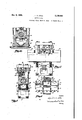
Fig. 15 is a sectional view corresponding to Fig. 4 butillustratinga portion of the machine adapted for finishing the bottom surface or a cylinder block. Fig. 16 is a central sectional view showing the construction of the valve Illa, and its con-- nections'; T e Fig. 1'7 is a sectional view through the-valve Fig.v 18 is a Fig. 19 is a sectional view through the valve M5; I Fig; 20 is a--sectional view through the valve I34; and q Fig. 21 is a sectional view through the valve I26.
The invention as herein set forth is described, for purposes of illustration, as applied to the machining of engine cylinder blocks, but it will be apparent that work pieces of various sorts and forms and requiring various machine operations may be operated upon in accordance with the process and by the apparatus herein set forth. Furthermore as herein described, the invention comprises machines for broaching and drilling the work pieces, but other types ofmachines adapted. for cutting the work may be employed in conjunction with or in place of the driIling or the broaching, machines herein described.
The machine illustrated in Figs. 1 to .4 and 5 to 12 is particularly adapted for breaching operations, it being shown as provided with broaching tools'for finishing the upper surfaces of the cylinder banks of a V-shaped cylinder block of an automobile engine. I The broaching machine, which will be referredto generally byfthe refer- .ence numeral l0, comprises a fixed base H, the upperv portion of which is arranged to carry and support workcarryingfixtures such as the fixture l-2. in which'the engine block or other work piece is eceived and held.. The fixture 12 is slidably supported on the guide or track ll of the'machine base,.the fixture and the base being-provided with cooperating flat surface theupper portion. 1
sectional view through the valve plates l5 so that the fixture can be readily moved along the guide. On opposite sides of the fixture are downwardly and inwardly extending arms or sides I6, preferably provided with rollers i'l 8 which operate in engagement with the inclined" sides It of the base guide, the sides 16 cooperating with the sides of the guide to prevent excessive movement of the fixture out of the line of forward travel centrally of the machine. How- 10 ever, there is some small distance or clearance between the sides of the guide and the fixture sides l5 so that a small limited lateral movement of the fixture on the track is possible.
The engine block II is preferably provided with several small locating holes drilled in the bottom of the block, and cooperating with locating pins 2| which project up from the bottom of the fixture to locate the block in the fixture in a definite predetermined position with respect :0 thereto. The lower side of the block is finished to provide a'smooth surface which rests on finished support strips 22 fixed in the fixture, and the block is held firmly. against the support strips by means of clamps 23 which press downwardly as on opposite end portions and thus securely hold the block against any movement in the fixturewith the block definitely located by the cooperating pins and holes 2! and 20. Before tightening the clamps a stop screw 24 which is,threaded N in the side of the fixture is turned until its inner end abuts abainst the end of the cylinder block for transferring lateral forces, created on the block during breaching, directly .to the fixture wall.
as The base Ill supports the fixed frame portion of the machine which is herein shown as embodying four rods or pillars 25 carrying the frame top 26. The machine frame mevably carries a head 21 which is adapted for vertical movement,
a being provided with vertical bores through which the rods 25 extend, the reds thus guiding the head in its vertical movement. The weight of the head is counter-balanced by springs 28 which bear at their lower ends against the base I l and which press upwardly on the lower side of the head.
Near the upper portion of the head, as shown in Figs. 1 to 3, the latter is provided with four links ll which are pivotally connected at their lower ends to pins 3| carried by projections 32 fixed on the head. The upper ends of the links III are pivotally connected to cooperating links ll which are pivoted at their upper ends to projectiens 34 of the frame top 28. The projections 34 are preferably adjustable vertically with respect to the top 26 so the head can be adjusted to a desired horizontal position and providing an adjustment by which the lower limiting posi-- tion of the head may be varied. The links and 33 provide toggle connections between the upper portion of the head and the frame top, the pins which interconnect the links In and 33 being connected to operating arms 36 which extend to operating crank pins 31 and 38 projecting laterally from two operating disks 40. When the op- 7 gear 43 which engages with a rack 44 movable v tiens.
longitudinally in the upper portion of the head. The rack may be moved to the right from the position shown in Fig. 3 by supplying fluid under pressure to the pressure fluid operated cylinder 45, one end of the rack being formed as a, piston 46 operating in the cylinder 45. The fluid, such as oil or the like, may be supplied through a suitable pipe line in a manner to be more fully described. Pressure fiuid may also be supplied to a pipe connected to an opposing or right-hand cylinder 52 by means of which the rack is moved toward the left or to the position shown in Fig. 3 in order to raise the head vertically away from the work.
The head 21 slidably supports the carriage 54 to which the broaching tools 55 are fixed, coop;- erating guide surfaces 53 being arranged on the head and on the carriage sothe carriage is movable vertically with the head but can slide horizontally ,in the head during broaching opera- The carriage is provided with or fixed to a cylinder 55 which may be supplied with fluid under pressure in order that the carriage may be moved toward the right (see Fig. 3) thus bringing the broaching tools into effective or cutting engagement with the work. The piston 58 which cooperates with cylinder 56 is fixed to the v head 21, the cylinder 56 being in fluid-tight sliding engagement with the piston at 59. The carrlage 54 is returned or moved toward the left by supplying fiuid under pressure tov a pipe which extends through the piston 62 which is fixed to the head and which is adapted for cooperation with the return cylinder 63 of the carriage.
When the cylinder 45 is energized the head is moved down, bringing the lower end 61 of the head down firmly against the-upper end portions of the fixture l2 .with a force that preferably exceeds the upward reaction force that will be created when the breaching tool engages and operates on the work. Initial adjustment of the projections 34 provides for the regulation oi the downward forces created by the head portion Bl against the fixture so that a tension load is applied initially to the rods somewhat in excess of the vertical reaction forces produced by the breach when engaging the work. Thus all the machine parts are pre-loaded to such an extent as to prevent yielding movement of the parts during operation. After the head is moved down fiuid is supplied to cylinder 56 to cause the broaching tool carriage to move horizontally for cutting efiect upon the work. The speed of the breach may be about 25 feet per minute orat any other suitable speed.
As will be seen from Figs. 1 and 3, the track or guide l4 of the base extends longitudinally from a central portion upon which a fixture is arranged when the work it carries is being broached. The fixture I2 is followed by a second similar fixture He. also mounted on the track provided by the guide l4. Furthermore, another fixture l2b is arranged ahead of the fixture l2 and still other fixtures precede fixture l2b as may be required.
Suitable means are provided for moving the line of fixtures along step by step through a distance equal to the length of a fixture, so that when the broaching operation is completed on the work carried by the fixture l2, the fixture I20. will be pushed ahead a distance corresponding to its length, thus advancing the fixture I2 and pushing both the fixture l2 and the fixture l2b along so as to bring'the work carried by fixture lZa into position for a broaching operation.
vis a large passage 16 in the base Il of the mafixtures.
l4,"the fixture is pushed onto a rotatable table a v 2,189,402 Each of the fixtures is providedwitha iocat-' ing pin or projection 13 which extends' upi'tiardiy and which is adaptedlto be'receivedby-a'cooper ating locating recess 14 provided -i H 1 side fthehead portion 61. If ltheamount of feedgiven' to-the line of fixturesgisfnot abso; lutely accurate, the locating 'pinnlihand thewico- 1 operating hole l4 will exactly positionithe-fixture carrying the work to be broached when the he ad of the machine descends. The'co'operating pins I3 and holes I4 also serve to shift the fixture transversely of the line 'ofadvanceany small distance required to bring the, work into its exact position, as the fixture merely floats on the top of the track, and is not exactly posi-fl tioned until the head of the machine descends. Each fixture is preferably provided with project.
-ing studs. 15 at its ends, the distance between the ends of the studs 15 of each fixture being some predetermined distance corresponding to the length of a feeding step of the line of fixtures One of the studs I5 of each fixture is permitted some small limited yielding movement with respectto-its fixture, being pressed outwardly by a spring as shown in Fig. 9. The spring 70, however, is strong enough to normally maintain'the stud extended during advancing or feeding steps of the fixtures.
The fixtures may be fed forward by suitable is operated in timed relationship to the ma chine and which is adapted to be. moved forward the length of a fixture and to be then returned so as to engage another. fixture brought up into alignment with the advancing line.
As will be apparent from Figs. 2 and 3, there chine, large enough for the return passage of the After advancing tothe end of the track which is then-turned so as to invert the fixture.
. after the work has been removed .from it. The
inverted fixture is then moved back through the v machine, passing through the space 16 in a direc- In its rechine construction. In its suspended position the weight of the fixture is carried by the rollers I"! which operate along the inclined guide surfaces l8' of the tracks TI. The return movement of the fixtures is also a step by step movement,
fiuid pressure or other means being arranged to shove the returning line of fixtures through steps corresponding in length to the length of the fix-- tures.
The broaching machine that has been described is adapted for broaching large surfaces of comparatively large work pieces such as engine blocks .and the like.
Each broach 55 is provided with a large number of cutting edges, as shown in the fragmentary view, Fig. 5,. these edges extend ng at a suitable lateral angle. Each cutting edge projects below the level of the preceding cutting edge and the various cutting edges therefore operate successively'to surface the workpiece. The
total amount of metal taken off by the broach may be about .18" in a broach having about thirty lowthepreceding-tooth.-' .The broach is prefer ably mcuntedadjustably in the broach carriage teeth with each toothprojecting about .006 beby awe'dge 68' which bears at its upper surface on a horizontal surface portion 68a of the carriage. The plane containing the cutting edges is substantially parallel to the top surface 58b of the broach 55, Longitudinal. adjustment of the broaching tool 55, effected by an adjusting screw 1 69 or the like has'the effect of lowering or raising of the entire broach through small distances sufilcient to compensate for wear of the cutting edges. Bolts 69a securely clamp the broach to the cariage in any desired position of adjustment;
The movement of the broach in the machine 'describedis transverse to the direction in which the work is fed to, through and from the machine so that the chips removed by the broach will fall on opposite sides of. the'track which supports the fixtures, or will fall, within the fixture and between the ends of the fixture and the work. Then when the'fixture is inverted at the end of the machine or at the end of a line of machines; thechips fall out and can .be readilyremoved, but they will not fall on the guide track or rail which is therefore kept clean at all times.
While the machine In may be employed independently of other machines for carrying out a desired broaching, operation, it is a part of the presentinvention that a machine of this character, or a machine adapted for machining operations on successive work pieces arranged for advancing movement through the machine in the general manner above set forth will be employed in conjunction with other machines adapted to perform related or sequential operations that have heretofore been performed by different and unrelated tools; Thus the broaching machine in as shown in Fig. 14 may be one of a series of machines arranged in a line comprising the machines Ill, lfla, I01), I00, llld, I06, I01, and additional machines .as may be required, For examp1e,let us assume it is desired to broach the cylinder banks, then broach the horizontal-top of the block and to follow these operations by a number of drilling, tapping and boring operations. All these operations may be quickly and accurately carried out in sequence by the line of machines l0, Illa, lllb, etc., the machine Illa generally corresponding to the .machine l0 but provided with a broaching tool adapted to cut the horizontaltop surface of the cylinder block. The machine Illb is provided with a number of drills or other similar cutting tools that perform the required drilling operations in the cylinder banks. Machine. Iflc may perform tapping operations on the drilled holes.- Machine IOd can drill other holes. Machines Hie and lOf-can bore and finish .the cylinder walls. All the machines of the line, however, are providedwith similar and cooperating guide or track means, and are arrangedin line, with the guide tracks or rails of one machine forming continuations of the guide tracks or rails of an adjacent machine so that the fixtures can carry the work to a machine and from it to the last machine in the line, stopping at each ma chine for the required operation on the work before it advances another step. The space between the machines corresponds to the length of one or more fixtures so that while one fixture is in operating position in each machine, interposed fixtures are provided betweenthe two mach nes,
ready tobe advanced to a proper location in a machine at the next' feeding stroke. Thus the fixture 12b is interposed between the fixture l2in abled to remove the clamps 23 applied to the hor" izontal top of the block, and replace them in engagement with the cylinder banks in such a way as to leave the horizontal top without obstruction so that surface can be finished in the machine, Ila. This changing of the clamps is carried out by the operator while the fixture I!) is stationary between the two machines.
At the left-hand end of machine I0, as viewed in Fig. 14, the track continuation is in the form of a rotatable table 80 having upper and lower fixture guide surfaces arranged normally in line with the upper and lower guiding surfaces or tures through a distance equalto the length. of
' to the length of a fixture.
tracks of the machine. However, thetable is rotatable about a horizontal axis which is' parallel to the line of advancing movement of the fixtures and centrally below between the upper and lower tracks. The empty fixtures are returned by suitable indexing means such as a fluid pressure pushing cylinder 08a arranged at the end otthe line, providing for step by step movement of the fixtures with each step corresponding Each time the line of returning fixtures is moved to theleft' as viewed in Figs. 6 and'i4 a fixture is moved on to the lower guide rails of the table 00. The table 00 is then rotated through 180 by meansof a turning cylinder 0I shown in Fig. 7 having rack teeth engaging with a gear 02 fixed to the table. When fiuid pressure is supplied to either end of the cyl- Inder the cylinder moves endwise and rotates the able 180', the direction of rotation depending on which end of the cyliruier is energized. After moving the table through 180 the fixture on the table is brought into exact alignment with the upper fixed guide surfaces of the machine I0. A cylinder block is then applied to the fixturewhile it is on the table and before it is advanced into the central portion of the machine I0. The fluid pressure cylinder 00 is then energized by sum pressure so that the cylinder is moved to the right as viewed in Fig. 6 and the fixture is thus pulled forward by the arm 01, which engages a depending wall 01a on the fixture, through a distance sumcient to take -up any small space between the fixture on the table, to whichthe cylinder block is applied, and the fixture I2a ahead of it, and to move the whole line of fixa fixture. This places a fixture to which a work piece has been applied one step closer to the machine II andadvances the other fixtures in the line the proper predetermined distance. I The feeding cylinder is preferably housed for slidable movement in an opening in the track forming portion of the machine base. The lug'0lb on the arm 01 is movable in a slot extending longitudinally along the upper fixed track or guide. The lug 81b is carried yieldingly by arm 0'! and is adapted to spring up into engagement with the wall 01a of a fixture on the table when the cylinder 00 reaches the end of its movement to the left. The return feed for the fixtures is of sim- Ilar construction except that the lug 01d extends downwardly for engagement with the inverted fixture on the table 00a, which is rotated by a gear 02a, and a rack on the turning cylinder 8Ia.
In the machine I0 the banks of the cylinders arebroached as above described, the fixture then advancing to the space between the machines I0 and Ma. The next step is the advance of the fixture into the machine I0a which provides the desired broaching operation on the top of the cylinder block. A further step carries the fixture along the tracks extending between machines I01: and I0b. Another step takes the fixture into the machine I0b in which the desired drilling operations are carried out on the cylinder banks. Each fixture thus travels the entire length of the line of machines stopping at each machine for the intended operation and then moving on again until all the operations are completed. The various operations are rapidly carried out as the broaching operation is very rapid, and as no time is lost in positioning the work pieces in the various machines. Each fixture is exactly positioned in a machine by the holding means or head with which each of the machines of the line'is provided. It will be understood that each holding means of each broaching and drilling machine is provided with locating holes in a movable clamping or holding head, cooperating with the pins 13 of the fixtures, the springs I0 of the studs I permitting limitedyielding compression of the fixtures, if necessary, between any two machines. When the fixture reaches the end of the line of machines it is rotated through 180 by the table 8011 thus dumping'the chips from it and moving it into alignment with the rails or guide surfaces on the lower side of the machine along which the fixtures are returned. When the fixture reaches the table 80a, the work, or cylinder block is removed from it before the table is inverted.
After passing through the line of machines comprising .the machines I0, Illa, I0b, etc., the
ends of the cylinder block may be broached, the blocks first being applied to suitable fixtures for exposing their end surfaces. The fixtures are supplied to the machine I0h which carries out this operation and which may be followed by an additional machine or machines IN and I01 for carrying out other operations if desired, by tracks and advancing means similar to those employed in machines I0, I 0a, I0b, etc.
Before supplying the fixtures to the machine line comprising machines I0, I On, I0b, etc., the bottom of the cylinder blocks may be broached in amachine I0'p, and any drilling or other operations required in addition may be carried out in .a machine or a plurality of machines Him, I0n,
etc., the machines I0p, I0m and I On being arranged in a line similar to the line including maing the blocks to the fixture 98, spots 91 are,
milled on the cylinder banks, and the cylinder block can then be held on the fixture 98 with the finished spots bearing on the finished inclined surfaces of the fixture, as shown in Fig. 15. The
broach I00 is carried by a carriage IOI which is similar in construction to the carriage of the machine I0, the other parts of the machine also corresponding to the form of construction previously described. The tend from a rotatable ta le I02 at'the left-hand end of machine Hip as viewed in Fig, 14, through and between the machines Hip, Iilm and In, ending with a rotatable table I03 which inverts the fixtures so that they can be returned to the left after passing through the machine Illn. The advancing and returning means may be similar to the fiuid pressure cylinders previously described uiderails or tracks exalong to a point adjacent the table 102.
It will be-apparent that the various operations carried out by the several machines in a line .such
as the line comprising machines I0, Illa, Illb, etc., may notall require the same amounts of time-for completion. 'I'hus the broaching operation'may.
be carried out in only a small portion of a minute, while a somewhat longer period of time may be required-for the drilling operations of the machines IIlb, IIlc, etc. The amount of time required for the longest operation will therefore determine the time period between advancing steps of the fixtures. The various operations, however, are
carried out on a plurality of work pieces-in timed- .relationship and in proper sequential manner so that all the machine operations consume only a comparatively small amount of time. Thus there are a plurality of interrelated units adapted for performing a plurality of related or sequential operations of a character heretofore performed by different and unrelated tools. The operator of the several machines of a line-isnot required to carefully chuck each piece in each machine,
from the fixtures at the end of the line for trans-,j fer to another line of machines or to a conveyor by means of which they can be removed to a desired point. 1
The'various controls for receiving and lowering the head, for advancing and returning the broachQ and for indexing and turning the fixtures at the end of a line are shown diagrammatically in Fig. 13, Figs. 11 and 12 illustrating the positioning of some of the parts of the fluid pressure control system as applied to machine I0. Fluid pressure is supplied by four pumps operated by the two motors I II that can be mounted upon the raising and lowering cylinders 52 and 45. four pumps indicated by the reference numeral H supply oil or other fluid under pressure to a common pressure line H2, receiving the fluid from. the supplytank H3 which can be housed in'the machine top 26. The fourth pump IIIJ supplies fluid under pressure to another pressure line I I2a. Inasmuch as the motors move up and down with respect to the tank, suitable telescopic or flexible connections H4 are provided in the supply pipes leading from tank to pump. H5
designates relief valves arranged to return fluid I from the higher pressure sides of the pumps back to the tank when some predetermined pressure is reached.
At the start of an operation the operatorpu'lls a starting lever I I6 downwardly from the position I shown, mechanically moving a control valve II! to a second position shown in dotted lines. This connects the pressure line H2 through a pilot line 217 to the left-hand side of piston valve H'la moving the piston to the right and thus connecting line II2c to a line H8. The construction of valve I I'Ia will be apparent from Fig.
ment of the fixtures.
The operator Three of these 16. Line N20 is connected to'pressure line H2 through a pressure reducing. valve 200. When the piston of valve I I'll: moves to the right fluid is exhausted from the right-hand side of the valve through a line H2d back to the tank.
'Line H8- is in communication with'the righthand side of the feeding cylinder 88. The cylin der 83 is thus moved to the right when the valve IIIa is moved as above described, pulling a fixture from the upper side of the table 80 through a distance corresponding to the length of the fixture; 'At the same time fluid under pressure is supplied'from the pipe H8 to the left-hand-end" of cylinder 88a.which causes the return move-' At the end ofthe feeding step of the fixtures, a pivoted finger or latch I I9 on the movable cylinder 88 engages one of the eight arms on pilot valve I causing the rotarvpilot valve I20 to move clockwise 45 degrees from the position shown, supplying fluid asshown in dotted lines through valve I20 froma fluid pressure control or pilot line I2I to a line I22 which extends to the left-hand side of the control piston of a valve I23, the construction of which is similar to the valve I I'Ia'. The piston of valve I23 is thus moved to'the right opening communication from a line II2e 'to line I24 so that fluid is supplied to the end .of the cylinder Bla by means of which the transfer tables 80 and .80a are rotated. When the piston of valve I23 is moved to the right fluidis exhausted from. the right-hand side of the piston through line I22a which at that time connects to the tank through valve I2ll. vWhen the cylinders 8i and 8Ia moveto the left as above mentioned fluid is returned from the right-hand ends of these cylinders through line I24a which was placed in communication through valve I23 with return pipe 8a leading back to the tank.
Upon the energization ofline I22 as above men- .tioned fluid" is supplied under' pressure not only trolling arm I22d downwardly, this valve being controlled by a fluid operated piston. As the arm I22cl moves down, fluid is exhausted from the lower side of its energizing cylinder through line I'22e and through line I22) which connects to I22 a, at that time in communication with the tank. Downward movement of the valve controlling arm I22d pulls downwardly on a lug IHla fixed on'a valve I10 so that passages through valve .IIU' are then as shown in dotted lines Thus the fluid will now be supplied from a pressure line Hill) to a line I'Hlc leading to the 'right-. hand side of a valve I3I, similar in construction to the valve Hla. The piston of valve I3I is thus moved to the left immediately after the piston of valve I23 moves to the right. Such movement of the control piston of valve I3I places the supply pipe H20 in communication with line I32, and fluid is thus supplied'to the left-hand 'end of the cylinder 45 tov produce downward movement of the head of themachine, this downward movement 'of the head taking place imme diatelyafter the advancing movement of the fix-- This piston is provided with a lug I25 adapted 75 left-hand end of cylinder 8| and to the left-hand hmunicatl to operate a valve I24, shown in Fig. 21. Movement of the cylinder 3| to the left, therefore, flrst throws valve I25 counter-clockwise establishing flow through the valve as indicated in dotted lines in order to immediately reset or lift the arm I22d, fluid being supplied through the energized lines I22 and I22!) to line I22e and pushing upwardly on the piston controlling arm I22d, arm I22d snapping past the lug I10a which is still lowered, without effect. I
When the line I22c is energized as above described so as to pull down on the arm I22d; at the same time fluid is supplied through the line I22g to the upper side of a cylinder I10 pulling downwardly on an arm "to and thus rotating the valve II1 clockwiseback to its original position so that fluid will be supplied from line M to the right-hand side of valve II1a returning this valve to its original position and thus supplys ing fluid through the valve as shown by the arrow from line II2c to line I23. Fluid is thus supplied to the let -hand end of cylinder 08 and to the right-hand side of the cylinder so that they are promptly returned to their initial positions ready to engage other fixtures. Fluid'at the same time is returned from the other sides of the cylinders through line II8 now connected through the valve I I10 and through line I Ila back to the tank.
The rotary pilot valve I I20 alternately admits pressure from the pilot line I2I to the lines I22 and H21: upon each 45 degree clockwise movement of the valve, the return movement of the piston 03 being without effect on the valve .as the finger IIO is pivotally supported so it can swing back when the cylinder 00 is moved to the left. The valve I23 is therefore caused to alter- 'nately supply pressure flrst to one end of the cylinders 3| and Ola. and then to the other andto cause reverse movements of each transfer table. When the line I22a is energizedthe line I221 serves as a source of supply for fluid which can pass through the valve I24 to the line I22e for operation of the arm H241 and the valve I10. When the line I22 is energized the flow of fluid is from the line I22 to the line I22e. When the piston of valve I3I moves to the left as before mentioned, line I32 is energized and the piston 40 moves to the right causing counterclockwise movement of two arms I33 and "M which are flxed, in axially oflset positions, to gear 43. During the flnal movement of the piston 40 to the right, arm I33 engages a flnger I33b of valve I34, moving the valve clockwise about 45 degrees from,the positionshown. This movement of the valve I34 opens the passages through I the valve as shown in dotted lines, placing a line I35 in communication with the line I43 extending to the right-hand side oi. a valve I31, similar in construction to valve II1a, and also to the righthand of a valve I15,similar in construction to the valve II1a. The pistons of these valves thus move to the left, valve I31 then supplying fluid from a controlled pressure line I33 to a line I38 leading through valve I43 to the broach advancing or ram cylinder 53. This causes the broach carriage tomove to the right, its rate of movement depending on the amount of flow obtaining through the controlled line I34 which is provided 6 with a flow oontrolmeans I4I to produce the desired speed of movement of the broach. At thesam tlmethat line I33 is placed in comwith line- I33, the pump I I0*is placed, through line 2a, in communication with line 75 I344 so that all four pumps are eflective in moving the ram cylinder during the broaching operation. v
The ram continues moving to the right until stop'l42 on the broach carriage engages a pro- Jection I43 of valve I40, closing valve I40 against down flow or fluid although upflow is permitted through a suitable spring pressed closure providing for one-way passage of fluid at all times.
When the valve I40 is closed as above mentioned, the ram stops. At the same time the valve, I40 is closed, a second stop I44 operates a valve' I45 thus placing the pilot pressure line I40 in communication with a line I41 which extends to the upper side of a cylinder I10d for the control of an arm I10e. The flow of fluid through line I41 causes the arm I10e to descend and operate against a lug I10] which resets valve I10 and reestablishes the fluid passages through valve I10 os shown insolid lines. Normally the piston which controls arm I10e is held up by pressure prevailing through line I41a extending to the valve I45, this line being always open for flow through line I41a except when the ram stop I44 is engaged with it. When the ram engages the stop on valve I45 the line 10 is open to the tank through a line I41b.
It will thus'be seen that after the ram has completed its movement to the right, the valve I10 is reset to its original position and it will then open, the passage from line "011 to line I10 leading to the left-hand side of valve I3I. The valve I3I is thus operated to supplyfluid from line 20 to line I40 causing the rack to move to the left and thus raising the head. At the end of the raising movement of the head the arm I33a will be moved clockwise far enough to contact a finger I330 on valve I34 thus returning the valve I34 to its original position so that fluid is again supplied to line I36 leading to the left-hand side of valves I31 and I15. This operation of the two valves I31 and I shuts oil! the pressure supply to the line I39 and connects that line through the return pipes I15 back to the tank. At the same time a fluid connection is made through valve I31 from line I38 to a line I11 extending back to the tank so that the three pumps IIO are merely recirculating fluid without eflect. However, the fourth pump I I0 supplies fluid through the valve I15 to line I50, a single pump furnishing sufficient flow and pressure inasmuch as the diameter of the returning cylinder is considerably less than that of the advancing cylinder of the broach. Fluid passing through line 450 flows through valve I5I, which is open, and through line I52 into tlfi cylinder 53 thus returning the breach to its initial position after the head has been moved up away from the fixture. In line I52 is a choke of cylinder 03. However, the-valve I521]. provides 1 for free flow of fluid into cylinder 63. At the end of the returning movement of thebroach carriage,'a stop I54 automatically closes the valve I5I against downwards flow of fluid or to cylinder 03 although up flow of fluid is always permitted through a spring controlled closure in this valve so that the contents of the cylinder 63 can be returned to the tank through line I10 after operation of the valve I15 for such return flow.
It will be understood that the control lever I I6 is suitably mounted for the control of man chine I0. A valve similar to valve II1a is provided for each, of the other machines in the line m which the machine To is included, the right and left-hand sides of such other similar lvalves, all .being connected in parallel to the lines 201 and 2b respectivel'yuthrough suitable connections H'Id. These other valves operate similar control systems for the various other machines for their 3 moving elements so that all 'of the machines in the line can be started at the same time and their work completed automatically. The moving parts of the several machines are .then returned to their initial positions and after afsuflicient timeinterval has elapsed for all operationsof the various machines to be completed, the operator again throws the handle IIB to, cause another feeding step of the line of fixtures immediately followed by the indexing movement of the tables and the automatic operation of the various machines. The control means N6 of the valve ll! forms a single control device forinitiating the movements of all the various machines in the line.
While the process and apparatus herein described constitute preferred embodiments of the invention, it is to be understood that the invention is not limited to this precise process and apparatus, and-that changes may-be made thereinwithout departing from the scope of the invention which is defined in the appended claims.
What is claimed is; 1. In combination in an apparatus for machining work pieces, a machine line adapted to perform different successive cutting operations on work pieces, a line of similar fixtures each adapt;
ed to receive and hold a work piece, means for advancing the fixtures step by step through the machine line, and means for rotating a fixture at an end of the line about an axis parallel to its line of advance. I I
2. In combination in an apparatus for machin- 'ingwork pieces,a plurality of' machines arranged in line and adapted to perform diflierent cutting operations on work pieces, each machine having a cutting tool head, a continuous line of similar fix tures each adapted to receive and hold a work piece, a track passing through and extending between the machines, common means for advancing the fixtures step by step along the track, and
means on each cutting tool head for individually locating a fixture opposite thereto at the end of an advancing step.
3. The combination in an apparatus for machining work pieces, a plurality of machines adapted to perform different cutting operations on work pieces, a line of similar individual fixtures "each adapted to receive and hold a work piece and arranged in series one'after another,
. guide means for the support of said fixtures, said guide means extending-through the machines and 7 from one machine to another, rotatable transfer means for moving a fixture laterally out of its line of advance, and guide means for'the return of the fixtures in a line parallel but opposite to the line of advance, V
4. The combination in. an apparatus for machining work pieces, a plurality of machines adapted to perform difierent cutting operations said head for individually locating a fixture op-'-.
posite thereto, transfer means for moving a fixture out of its line of advance, and common means for advancing said fixtures step by step.
5. In combination in an apparatus for machining work pieces, a plurality of machines adapted -to perform successive cutting operations on work pieces, guide means extending through said machines and from one machine to another, a line of similar fixtures on said guide means each fixture being adapted toreceive and support a work piece, means for feeding the fixtures step by step a'succeeding machine locating means on each fixture for the location of the Work in predetermined position on the fixture, andcooperating locating devices on the machines and on the fixtures for the individual location of the fixtures in a predetermined relationship in any machine and for simultaneously urging a fixture securely against said guide means, a machine tool on each machine, and means for moving said machine tools toward. the fixtures for engagement with the work piece.
6. A machine of the character described comprising a frame having a stationary fixture guide,
a fixture mounted for bodily sliding movement on said guide and adapted to receive and hold a Work piece, a head movably mounted on said frame, means for moving. said fixture along said guide to a predetermined approximate position for operating said tool.
I 7. A broach machinefof the character described comprising a frame, a fixture guide fixed on said frame, a fixture slidably mounted for rectilinear movement on said'guide, a head movable on said frame in a direction toward said fixture, said head having a portion adapted to be brought into engagement with said fixture for'definitely locating said fixture and for holding said fixture securely against said guide, a surfacing broach movably mounted on said frame, means for moving said surfacing broach in one direction for cutting the work, and means for moving the fixture along said guide.
8. A machine of the character described comprising a frame, a fixture guide on said frame, a fixture slidably mounted on said guide for rectilinear movement thereon, a head movable on said frame in a direction toward said fixture, a broach carriage movably mounted on said head, means for moving said broach carriage in one direction for cutting the work, symmetrically opposedlocating means on said fixture and cooperating locating means on said head for the location of the fixture in the machine, and means for periodically moving the fixture along said guide.
9. A machine of the class described comprising a frame, a fixture guide in said frame, a fixture slidably supported upon said guide and having clamping means adapted to hold a work piece, a head movably mounted on said'frame, means on I said head .engageable with the fixture for holding thefixture against said guide, toggle, means for raising and lowering said head, a broaching tool mounted for r'eciprocatory movement in said head, and means for operating said broaching tool in said head.
10. A broaching machine of the character described comprising a frame, a work fixture guide in said frame, a series of fixtures slidablysupported for horizontal movement upon said guide and each having work clamping means adapted to hold a work piece, means for periodically moving the fixtures along said guide to advance the fix-- tures successively to a predetermined position in said machine, and a surface broaching tool carried by said frame for horizontal movement in a direction substantially transverse to the direction of movement of said fixture and engageable with a work piece positioned in said predetermined position.
11. A machine of the character described comprising upright members, a head movably mounted thereon, a work carrying fixture, guide means slidably supporting said fixture, a cutting tool carried by said head, means for operating said cutting tool, and means for moving said head towards and against said fixture to a predetermined position in which a predetermined force is exerted downwardly by the head on the fixture which is greater than the upward force on the head created by engagement of the cutting tool with the work.
12. A broach machine of the character described comprising a frame. a fixture guide on said frame, a fixture movably mounted on said guide having means adapted to secure a work piece in position thereon, a head movably mounted on said frame, fluid pressure means for moving said head toward said fixture guide, a surface broaching tool carried by said head, and means for reciprocating said broaching tool in said head, the direction of movement of the broaching tool being substantially transverse to the direction of the movement of the fixture along said guide.
13. A machine of the class described comprising a frame, a fixture guide in said frame, a fixture on said guide adapted to hold a work piece, a head carried by said frame, a tool carriage on said head, transfer means rotatable about an axis spaced from and parallel to the line of advance for receiving the fixture in a position adjacent the operating position, and means for-moving said a transfer means to invert the fixture.
14. .A machine of the character described comprising a frame, a fixture guide in said frame, a fixture on said guide adapted to receive and hold a work piece, means for moving said fixture along said guide, means on said frame for performing a cutting operation on the work piece, a rotatable table movable about an axis parallel to the line of advance of the fixture along said guide, means for rotating said table, and a return guide for the fixture, said table forming continuations of both said guides.
. 15. A broaching machine of the class described comprising a frame, a guide in said frame, work feeding means to advance successive work pieces along said guide to a predetermined position in said machine, a head movably mounted on said frame, means on said head for locating and holding a work piece in position, means for raising and lowering said head, a broaching tool slidably guided for horizontal reciprocatory movement in said head, and means for operating said broaching tool.
16. In combination in an apparatus for machining work pieces, a plurality of machines including broaching and milling machines arranged in line and adapted to perform different cutting operations on work pieces, each machine having a cutting tool head movable into cutting position and retractible to provide for feeding movement of the work pieces, said line of machines having a loading station, a cutting station in each cutting machine and an unloading station at the end of the line, a track passing through and extending between the machines, common means for advancing, the work pieces step by step along the track and means on each cutting tool head for individually locating a work piece oppositethereto at the end of an advancing step.
LYNDON C. COLE.
Priority Applications (1)
| Application Number | Priority Date | Filing Date | Title |
|---|---|---|---|
| US714044A US2139402A (en) | 1934-03-05 | 1934-03-05 | Machine tool |
Applications Claiming Priority (1)
| Application Number | Priority Date | Filing Date | Title |
|---|---|---|---|
| US714044A US2139402A (en) | 1934-03-05 | 1934-03-05 | Machine tool |
Publications (1)
| Publication Number | Publication Date |
|---|---|
| US2139402A true US2139402A (en) | 1938-12-06 |
Family
ID=24868561
Family Applications (1)
| Application Number | Title | Priority Date | Filing Date |
|---|---|---|---|
| US714044A Expired - Lifetime US2139402A (en) | 1934-03-05 | 1934-03-05 | Machine tool |
Country Status (1)
| Country | Link |
|---|---|
| US (1) | US2139402A (en) |
Cited By (2)
| Publication number | Priority date | Publication date | Assignee | Title |
|---|---|---|---|---|
| US2709395A (en) * | 1951-07-21 | 1955-05-31 | Cincinnati Milling Machine Co | Broaching machine |
| US3381348A (en) * | 1964-04-18 | 1968-05-07 | Patrignani Leonida | Transfer machines |
-
1934
- 1934-03-05 US US714044A patent/US2139402A/en not_active Expired - Lifetime
Cited By (2)
| Publication number | Priority date | Publication date | Assignee | Title |
|---|---|---|---|---|
| US2709395A (en) * | 1951-07-21 | 1955-05-31 | Cincinnati Milling Machine Co | Broaching machine |
| US3381348A (en) * | 1964-04-18 | 1968-05-07 | Patrignani Leonida | Transfer machines |
Similar Documents
| Publication | Publication Date | Title |
|---|---|---|
| US2392169A (en) | Machine tool | |
| US2722867A (en) | Method of and apparatus for machining blade airfoil surfaces | |
| US2808746A (en) | Work handling mechanism for machine tools | |
| US2669135A (en) | Machine tool construction | |
| US2603117A (en) | Template controlled machine tool | |
| US2139402A (en) | Machine tool | |
| US2570589A (en) | Transfer mechanism | |
| US2542986A (en) | Machine tool | |
| US1970023A (en) | Lathe | |
| US2486294A (en) | Machine tool transmission | |
| US2345494A (en) | Spar tapering and shaping machine | |
| US2381999A (en) | Work holding fixture for broaching machines | |
| US2063955A (en) | Apparatus for machining metal parts | |
| US2049444A (en) | Drilling machine | |
| US2103147A (en) | Machine tool | |
| US2372692A (en) | Material working apparatus | |
| US2368061A (en) | Milling machine | |
| US2643570A (en) | Multiple station center drive crankshaft lathe | |
| US3733142A (en) | Apparatus for simultaneously drilling and tapping a plurality of work pieces at each of a plurality of positions | |
| US2008010A (en) | Turret lathe | |
| US2042379A (en) | Metalworking apparatus | |
| US2389019A (en) | Vertical turret machine tool | |
| US2576341A (en) | Automatic transfer machine tool | |
| US2280230A (en) | Crankshaft broaching lathe | |
| US2349168A (en) | Metalworking machine |