US2139347A - Fuel pump - Google Patents
Fuel pump Download PDFInfo
- Publication number
- US2139347A US2139347A US73276A US7327636A US2139347A US 2139347 A US2139347 A US 2139347A US 73276 A US73276 A US 73276A US 7327636 A US7327636 A US 7327636A US 2139347 A US2139347 A US 2139347A
- Authority
- US
- United States
- Prior art keywords
- casing
- pump
- valve
- diaphragm
- stem
- Prior art date
- Legal status (The legal status is an assumption and is not a legal conclusion. Google has not performed a legal analysis and makes no representation as to the accuracy of the status listed.)
- Expired - Lifetime
Links
- 239000000446 fuel Substances 0.000 title description 16
- 230000000712 assembly Effects 0.000 description 13
- 238000000429 assembly Methods 0.000 description 13
- 238000010276 construction Methods 0.000 description 4
- 239000011521 glass Substances 0.000 description 4
- 230000000994 depressogenic effect Effects 0.000 description 2
- 238000000034 method Methods 0.000 description 2
- RYGMFSIKBFXOCR-UHFFFAOYSA-N Copper Chemical compound [Cu] RYGMFSIKBFXOCR-UHFFFAOYSA-N 0.000 description 1
- 229910052802 copper Inorganic materials 0.000 description 1
- 239000010949 copper Substances 0.000 description 1
- 238000004512 die casting Methods 0.000 description 1
- 230000000694 effects Effects 0.000 description 1
- 239000004744 fabric Substances 0.000 description 1
- 239000010985 leather Substances 0.000 description 1
- 238000004519 manufacturing process Methods 0.000 description 1
- 239000000463 material Substances 0.000 description 1
- 229920000136 polysorbate Polymers 0.000 description 1
- 230000037452 priming Effects 0.000 description 1
- 230000000284 resting effect Effects 0.000 description 1
- 238000007789 sealing Methods 0.000 description 1
- 239000013049 sediment Substances 0.000 description 1
- 239000007779 soft material Substances 0.000 description 1
- 125000006850 spacer group Chemical group 0.000 description 1
- 238000009987 spinning Methods 0.000 description 1
- 230000001502 supplementing effect Effects 0.000 description 1
Images

Classifications
-
- F—MECHANICAL ENGINEERING; LIGHTING; HEATING; WEAPONS; BLASTING
- F02—COMBUSTION ENGINES; HOT-GAS OR COMBUSTION-PRODUCT ENGINE PLANTS
- F02M—SUPPLYING COMBUSTION ENGINES IN GENERAL WITH COMBUSTIBLE MIXTURES OR CONSTITUENTS THEREOF
- F02M37/00—Apparatus or systems for feeding liquid fuel from storage containers to carburettors or fuel-injection apparatus; Arrangements for purifying liquid fuel specially adapted for, or arranged on, internal-combustion engines
- F02M37/04—Feeding by means of driven pumps
-
- F—MECHANICAL ENGINEERING; LIGHTING; HEATING; WEAPONS; BLASTING
- F02—COMBUSTION ENGINES; HOT-GAS OR COMBUSTION-PRODUCT ENGINE PLANTS
- F02M—SUPPLYING COMBUSTION ENGINES IN GENERAL WITH COMBUSTIBLE MIXTURES OR CONSTITUENTS THEREOF
- F02M59/00—Pumps specially adapted for fuel-injection and not provided for in groups F02M39/00 -F02M57/00, e.g. rotary cylinder-block type of pumps
- F02M59/12—Pumps specially adapted for fuel-injection and not provided for in groups F02M39/00 -F02M57/00, e.g. rotary cylinder-block type of pumps having other positive-displacement pumping elements, e.g. rotary
- F02M59/14—Pumps specially adapted for fuel-injection and not provided for in groups F02M39/00 -F02M57/00, e.g. rotary cylinder-block type of pumps having other positive-displacement pumping elements, e.g. rotary of elastic-wall type
-
- F—MECHANICAL ENGINEERING; LIGHTING; HEATING; WEAPONS; BLASTING
- F02—COMBUSTION ENGINES; HOT-GAS OR COMBUSTION-PRODUCT ENGINE PLANTS
- F02M—SUPPLYING COMBUSTION ENGINES IN GENERAL WITH COMBUSTIBLE MIXTURES OR CONSTITUENTS THEREOF
- F02M2700/00—Supplying, feeding or preparing air, fuel, fuel air mixtures or auxiliary fluids for a combustion engine; Use of exhaust gas; Compressors for piston engines
- F02M2700/13—Special devices for making an explosive mixture; Fuel pumps
- F02M2700/1317—Fuel pumpo for internal combustion engines
- F02M2700/1323—Controlled diaphragm type fuel pump
-
- Y—GENERAL TAGGING OF NEW TECHNOLOGICAL DEVELOPMENTS; GENERAL TAGGING OF CROSS-SECTIONAL TECHNOLOGIES SPANNING OVER SEVERAL SECTIONS OF THE IPC; TECHNICAL SUBJECTS COVERED BY FORMER USPC CROSS-REFERENCE ART COLLECTIONS [XRACs] AND DIGESTS
- Y10—TECHNICAL SUBJECTS COVERED BY FORMER USPC
- Y10T—TECHNICAL SUBJECTS COVERED BY FORMER US CLASSIFICATION
- Y10T137/00—Fluid handling
- Y10T137/7504—Removable valve head and seat unit
Definitions
- This invention relates to pumps and has been designed as an improved pump for supplying fuel from the fuel reservoir of a motor vehicle to the engine.
- the object ofthe invention is to provide a pump having superior characteristics such as freedom from leakage, simplicity in the process of assembling the parts, and freedom from noise in operation.
- the fuel pump is associatedwith a vacuum booster pump intended particularly for supplementing the engine manifold in the operation of a suction motorof an accessory such as a windshield cleaner.
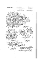
- Fig. 1 is a vertical section through the combined pump structure.
- Fig. 2 is a section on line 2-2 of Fig. 1.4
- Fig. 3 is a section on line 3-3 of Fig. 1.
- Fig. 4 is a perspective of the fuel pump valve assembly and the retainer therefor, parts being shown in disassembled relation.
- Fig. 5 is a plan View of the rocker arm and link assembly.
- numeral II is the upper of three casing members, these being preferably made by die casting.
- the member I I is recessed on its underside as at I3.
- an inverted cup I5 which may be of glass and which is held against a gasket I1 by a conventional bail I9.
- the top of the bail carries a screw 2l upon which is threaded a nut 23, the
- a closed air dome 21 Within the cup I5 and integral with the casing, II is a closed air dome 21.
- the casing is also formed with a wall 29 merging with the wall ,of the air dome at spaced points marked a and b in Fig. 2. Between the spaced vpoints a and b the wall 29 is spaced from the wall of the air dome 21 to form a pump inlet space or region 3 I.
- the upper wall ofmember I I also has formed therein an arcuate sediment collecting. recess 33.
- the upper part of the dome 21 together with the wall 29 is formed with a circular ledge 35 upon which is supported the lower and smaller edge of a funnel-shaped ring 31 to the top of which ring is secured a strainer 39 of wire cloth.
- a plurality of peripherally spaced fingers 4I extend from the top of ring 31 and engage the glass Cup.
- the strainer aslembly is thus resiliently -held in position.
- a passage 43 Leading into the space within the glass cup and communicating with the region outside the dome 21 and the wall 29 is a passage 43 extending through the wall of casing II as shown in Fig.' 2.
- An inlet pipe from the fuel 5 reservoir is to.be secured to the entrance 43.
- an outlet passage 45 extends through casing I I to the wall thereof as shown in Fig. 2.
- a conduit is to be connected for communicationwith the carburetor of the engine.
- the recess I3 is the pump chamber, and that fuel enters it by way ,of passage 43, through the screen 33 and then through space 3l. From the pump chamber 15 the fuel passes into the domev21 and out through passage 45. Controlling the entrance and exit are inlet and outlet valve assemblies.
- the inlet valve assembly, marked 41 is beneath the flared opening from space 3
- the outlet valve assembly, marked 49 is inthe communicating passage from the pump chamber to the dome.
- the two valve assemblies, 41 and 49 are identical in construction and are illustrated in Fig. 1 and Fig. 4.
- Each valve as- 25 sembly consists of a disc valve 5I formed toengage a seat 53, the seat being the smaller diameter part of ⁇ an apertured ring 55.
- a stamping 51 has a circular edge 53 bent over and engaging the outer face of ring 55.
- the stamping surrounds the outer periphery of ring 55 and is inwardly bent to engage the opposite face of the larger diameter portion as shown at 6I.
- the stamping is then extended to form a ring portion 63. It is within this ring portion that the 35 disc valve 5I reciprocates to and from its seat.
- the stamping then extends as shown by Fig. 4 to form an abutment for the spring of the valve.
- Inlet valve assembly 41 is positioned as shown by Fig. l and Fig. r4 with the face 59 engaging the casing wall around the passage between space 3
- Outlet valve assembly 49 is inverted so that the face 5I engages the annular wall between the pump chamber and the dome 21.
- a valve clamp or 45 retainer 51 shown in detail in Fig. 4, is provided with openings 69 for the passagecf suitable fastening means by which it may be secured to the underside of casing Il.
- This clamp has opposite arcuate arms 1I and 13. Arm 1I engages face 6I 50 of valve 41 and arm 13 engages face 53 of valve 49.
- a single easily secured retainer holds both valve assemblies in position. In this -way the cost oi' 55 tioned by a retainer 81.
- the intermediate pump casing member is designated by numeral 15.
- Fastening means 11 clamp casing members I I and 15 together with the pump diaphragm 80 therebetween. Casing.
- member 15 has an inner part 19 with an apertured wall 8
- an oil seal disc 85 formed from soft material such as'rubber or leather. It is posi-
- the retainer has at its lower end a flange seated on the casing member.
- a springl 89 engages the retainer flange at its lower end and a spring guide washer 9
- is seated on a shoulder of stem 83 together with diaphragm protecting washers 93 and 95, the former beneath and the latter above the diaphragm 8.0.
- washer 95 there is press-fitted on the stem a washer 91.
- l Washer 91 has a central stepped portion at 98.
- the assembly of diaphragm and washers is then rigidly secured by riveting or spinning over the hollowed end of rod 83 as shown by Fig. 1.
- the recess in washer 91 provided by the stepped construction takes care of any copper shavings which may be produced when the washer is press-fitted over the stem which is to be copper-plated. Since washer 91 is fitted on the stem a fixed relationship exists be.- tween the position of the diaphragm and the-fiat on its stem 83, which flat must be correctly posil bers.
- 05 is secured by fastening means
- 09 is seated upon a suitable abutment within casing 99 and engages diaphragm protecting washer the latter being depressed centrally toposition the spring as at I3.
- Upper washer I I is secured to the diaphragm and to the lower washer byv rivets I I1 which also secure an additional washer
- the lower casing has suitable inlet and outlet openings at
- the operating means for the two pumps is located in the intermediate chamber 15 and a portion of the operating means vprojects from casing 15 into the 'engine casing when the casing 15 is clamped to the engine casing, provision for which is shown by openings
- a pivot pin'l31 is press-fitted into casing 15 and extends across an opening in flange
- 39 is journaled on the pin
- extends into the path of movement of cam
- a U-shaped link spacer and spring seat is shown at
- the seal has an opening
- the oil sealing devices for the fuel pump stem and for the passage between the crank case and pump casing eiectively prevent damage to the diaphragms from heated oil within the crank case.
- a leak-proof assembly is providedfor the connection between the vacuum p'ump diaphragm and its stem.
- the sliding contact between the parts rotating Ion the pivot pin bushing prevents noise.
- the novel valve assembly is oi importance, particularly for purposes of assembly and replacement. Both valves are alike and assembly and replacement of both is simultaneously eiected by the attachment or removal 1 oi a simple retainer.
- the use of the bushing to take the load of the rocker arm and links prevents any loosening of the pivot pin in the casing.
- a fuel pump having a casing member constructed to form a pump chamber wall with inlet and outlet passages, inlet and outlet valve assemblies controlling said passages, said valve assemblies being of identical construction but assembled in inverted relation, and a single clamp having a plurality of biiurcated arms embracing ⁇ ⁇ said openings, said valve assemblies being identical but positioned in inverted relation the one to the other, and a single clamp secured to the casing and having a plurality of biiurcated arms engaging said valve assemblies.
- a casing recessed on one side and having a movable member to cooperate with the casing and constitute a variable volume pump chamber, adjacent inlet and outlet openings in said casing, inlet and outlet valve assemblies in said openings, said valve assemblies being identical but positioned in inverted relation the one to the other, and a single clamp secured to the casing and engaging said valve assemblies said casing openings having'coplanar shoulders, a
- first one of said valve assemblies having an end ⁇ face engaging one of said shoulders and a second.
- valve assembly having a mid portion face engaging the other shoulder, said clamp engagingva mid portion face of the rst valve assembly and an end face of the other valve assembly.
- each of said valve assemblies comprising an apertured ring having parts of unequal diameters, a valve4 disc within said ring 'and engaging as a seat the smaller diameter part of the ring, a spring engaging said disc and a stamping secured to said ring and forming an abutment for said spring.
Landscapes
- Engineering & Computer Science (AREA)
- Chemical & Material Sciences (AREA)
- Combustion & Propulsion (AREA)
- Mechanical Engineering (AREA)
- General Engineering & Computer Science (AREA)
- Reciprocating Pumps (AREA)
Description
Dec. 6, 1938. A. M. BABITCH ET AL. 2,139,347 FUEL PUMP 4 Filed April a, 193e 2 sheets-sheet 1 Z 29 S 217 i5 /i/ 53 y si ff 5 A lf. l;
VIC' r A. M. BABlTcH ET AL 2,139,347
FUEL PUMP 2 Sheets-Sheet 2 Filed April 8, 1956 m /ff 7 @awww 2W, 50a/21m@ Patented Dec. 6, 1938 PATENT OFFICE FUEL PUMP Abraham M. Babitch and Gordon W. Harry, Flint, Mich., assignors to General Motors Corporation, Detroit, Mich., a corporation of Delaware Application April 8, 1936, Serial No. 73,276
4 Claims.
This invention relates to pumps and has been designed as an improved pump for supplying fuel from the fuel reservoir of a motor vehicle to the engine.
The object ofthe invention is to provide a pump having superior characteristics such as freedom from leakage, simplicity in the process of assembling the parts, and freedom from noise in operation.
Other objects and advantages will be understood from the following description.
In the illustrated embodiment shown in thev drawings the fuel pump is associatedwith a vacuum booster pump intended particularly for supplementing the engine manifold in the operation of a suction motorof an accessory such as a windshield cleaner.
In the drawings:
Fig. 1 is a vertical section through the combined pump structure.
Fig. 2 is a section on line 2-2 of Fig. 1.4
Fig. 3 is a section on line 3-3 of Fig. 1.
Fig. 4 is a perspective of the fuel pump valve assembly and the retainer therefor, parts being shown in disassembled relation.
Fig. 5 is a plan View of the rocker arm and link assembly.
Referring by reference characters to the drawings, numeral II is the upper of three casing members, these being preferably made by die casting. The member I I is recessed on its underside as at I3. To its upper surface there is secured an inverted cup I5 which may be of glass and which is held against a gasket I1 by a conventional bail I9. The top of the bail carries a screw 2l upon which is threaded a nut 23, the
latter engaging a cup-shaped stamping 25 in contact with the glass cup I5 to hold it in position.
Within the cup I5 and integral with the casing, II is a closed air dome 21. The casing is also formed with a wall 29 merging with the wall ,of the air dome at spaced points marked a and b in Fig. 2. Between the spaced vpoints a and b the wall 29 is spaced from the wall of the air dome 21 to form a pump inlet space or region 3 I. The upper wall ofmember I I also has formed therein an arcuate sediment collecting. recess 33. The upper part of the dome 21 together with the wall 29 is formed with a circular ledge 35 upon which is supported the lower and smaller edge of a funnel-shaped ring 31 to the top of which ring is secured a strainer 39 of wire cloth. A plurality of peripherally spaced fingers 4I extend from the top of ring 31 and engage the glass Cup.
The strainer aslembly is thus resiliently -held in position. Leading into the space within the glass cup and communicating with the region outside the dome 21 and the wall 29 is a passage 43 extending through the wall of casing II as shown in Fig.' 2. An inlet pipe from the fuel 5 reservoir is to.be secured to the entrance 43. From the region within the dome 21 an outlet passage 45 extends through casing I I to the wall thereof as shown in Fig. 2. From the end of this passage a conduit is to be connected for communicationwith the carburetor of the engine.
It will now be understood that the recess I3 is the pump chamber, and that fuel enters it by way ,of passage 43, through the screen 33 and then through space 3l. From the pump chamber 15 the fuel passes into the domev21 and out through passage 45. Controlling the entrance and exit are inlet and outlet valve assemblies. The inlet valve assembly, marked 41, is beneath the flared opening from space 3| leading to the pump chamber. The outlet valve assembly, marked 49, is inthe communicating passage from the pump chamber to the dome. The two valve assemblies, 41 and 49, are identical in construction and are illustrated in Fig. 1 and Fig. 4. Each valve as- 25 sembly consists of a disc valve 5I formed toengage a seat 53, the seat being the smaller diameter part of `an apertured ring 55. A stamping 51 has a circular edge 53 bent over and engaging the outer face of ring 55. The stamping surrounds the outer periphery of ring 55 and is inwardly bent to engage the opposite face of the larger diameter portion as shown at 6I. The stamping is then extended to form a ring portion 63. It is within this ring portion that the 35 disc valve 5I reciprocates to and from its seat. The stamping then extends as shown by Fig. 4 to form an abutment for the spring of the valve. Inlet valve assembly 41 is positioned as shown by Fig. l and Fig. r4 with the face 59 engaging the casing wall around the passage between space 3| and the pump chamber. Outlet valve assembly 49 is inverted so that the face 5I engages the annular wall between the pump chamber and the dome 21. A valve clamp or 45 retainer 51, shown in detail in Fig. 4, is provided with openings 69 for the passagecf suitable fastening means by which it may be secured to the underside of casing Il. This clamp has opposite arcuate arms 1I and 13. Arm 1I engages face 6I 50 of valve 41 and arm 13 engages face 53 of valve 49. By this expedient it is unnecessary to make separate inlet and outlet valve assemblies. A single easily secured retainer holds both valve assemblies in position. In this -way the cost oi' 55 tioned by a retainer 81.
manufacture is reduced as is also the cost of assembly and removal of the valves.-
The intermediate pump casing member is designated by numeral 15. Fastening means 11 clamp casing members I I and 15 together with the pump diaphragm 80 therebetween. Casing.
The operating means for the two pumps is located in the intermediate chamber 15 and a portion of the operating means vprojects from casing 15 into the 'engine casing when the casing 15 is clamped to the engine casing, provision for which is shown by openings |33 in the casing flange |35. A pivot pin'l31 is press-fitted into casing 15 and extends across an opening in flange |35. A bushing |39 is journaled on the pin |31.
Within this angular J ournaled for rotation on the bushing is a rocker One end of arm |4| extends into the path of movement of cam |43 within the engine casing. The other end ,of rocker arm 4| is forked, its furcations 45 and I 41 rotatably supported on the bushing |39. Between the furcations |45 and |41 are the journaled ends of links |49 and |5|. Between these links and also Journaled on the same bushing is a shorter link |53. A U-shaped link spacer and spring seat is shown at |55. The legs of this U-shaped spring seat are mounted for rotation on the bushing |39 and are located between links |49 and |5| and straddle link |53. Adjacent the bend of the U of member |55 and on the legs are locating lugs |51. Cooperating with these lugs is a casing lug |59. The lugs on member- |55 and on the casing position a spring |6I. 'I'his spring acts to push the member |55 whereby it engages a surface |63 on the rocker arm |4| between the furcations and thereby functions to keep the rocker arm in contact with the cam. The surface |63 is also adapted to engage the end surfaces of links |49, |5I, and |53 and to swing saidlinks. The engaging surfaces between the links and the rocker arm afford lost motion connections whereby the pumps may operate with variable strokes. 'I'he mechanical mechanism involving the rocker arm and the links function to make the suction stroke-of the fuel pump and the discharge stroke of the vacuum pump. The springs 89 and |09 serve to make the other strokes of the two pumps. Links |49 and |5| are brought into contact at their extreme ends as shown in Fig. 5. The ends are shaped into hooked form as may be seen in Fig. 1 where they are extended through an opening in the flat portion |65 of stem |25. Similarly the hooked end |61 of link |53 is v interlocked with the flat end |69 of stem 83. In
assembling the parts it will be seen that the flats on the stems must'be positioned as shown, and since the-flats have a fixed relationship to the diaphragm in the case of bothipumps, predetermined positions of the diaphragms will insure the correct relationship of the stems with the links.
It is desirable that the hot oil should not pass from the crank case through the opening into the pump casing provided for the passage of the rocker arm. Such oil may damage the diaphragm and the oil loss may become serious. .,To that end a plate or seal |1| shaped as shown in Fig. 3 is placed over the casing flange |35, its
- edge resting on a ledge |13 of the casing as shown in Fig. 1. The seal has an opening |15 and the rocker arm I4| has surfaces 11 and |19 snugly fitting the upper and lower Walls of the seal opening as the rocker arm rotates on its pivot.-
has apertured depressed regions as at |83. After the apertures are positioned to surround the tenons, the latter are staked over the seal to hold it as shown in Fig. 2. It will be seen that in the staking process vthe end of the tenon is not clamped against the seal. In this way slight movement of the seal is provided to accommodate any irregularity in the location of the rocker arm which snugly fits the opening in the seal as explained above. Provision is made for the return of any oil which may enter the pump casing from the crank case. In the lower part of the casing flange |35 is a pocket |85 within which any oil passing around the rocker arm may collect. A flap valve |91 of flexible material and secured to the seal I'H covers an opening |89 communicating with the crank case. This valve is secured by suitable fastening means ISI. The oil may return to the crank case through this valve, but the valve closes against the passage of oil from the crank case.`
Among the advantages resulting from the novel pump structure described above are the following: The screen is not clamped between covers as in many prior constructions. Leaking, which would effect priming of the pump, is therefore avoided. The provisions to prevent rotation of,^
the diaphragms relative to their stems is of help in assembling the parts because the stems must be located in predetermined positions of rotation to engage the links. The oil sealing devices for the fuel pump stem and for the passage between the crank case and pump casing eiectively prevent damage to the diaphragms from heated oil within the crank case. A leak-proof assembly is providedfor the connection between the vacuum p'ump diaphragm and its stem. The sliding contact between the parts rotating Ion the pivot pin bushing prevents noise. The novel valve assembly is oi importance, particularly for purposes of assembly and replacement. Both valves are alike and assembly and replacement of both is simultaneously eiected by the attachment or removal 1 oi a simple retainer. The use of the bushing to take the load of the rocker arm and links prevents any loosening of the pivot pin in the casing.
Reference is made to our patent for Fuel pump, 2,036,452, dated April '7, 1936. Certain matter shown but not claimed herein constitutes the subject matter of claims of that patent.
We claim:
1. A fuel pump having a casing member constructed to form a pump chamber wall with inlet and outlet passages, inlet and outlet valve assemblies controlling said passages, said valve assemblies being of identical construction but assembled in inverted relation, and a single clamp having a plurality of biiurcated arms embracing` `said openings, said valve assemblies being identical but positioned in inverted relation the one to the other, and a single clamp secured to the casing and having a plurality of biiurcated arms engaging said valve assemblies.
3.'In a pump, a casing recessed on one side and having a movable member to cooperate with the casing and constitute a variable volume pump chamber, adjacent inlet and outlet openings in said casing, inlet and outlet valve assemblies in said openings, said valve assemblies being identical but positioned in inverted relation the one to the other, and a single clamp secured to the casing and engaging said valve assemblies said casing openings having'coplanar shoulders, a
first one of said valve assemblies having an end` face engaging one of said shoulders and a second.
valve assembly having a mid portion face engaging the other shoulder, said clamp engagingva mid portion face of the rst valve assembly and an end face of the other valve assembly.
4. The invention defined by claim 2, each of said valve assemblies comprising an apertured ring having parts of unequal diameters, a valve4 disc within said ring 'and engaging as a seat the smaller diameter part of the ring, a spring engaging said disc and a stamping secured to said ring and forming an abutment for said spring.
. ABRAHAM M. BABITCH.
GORDON W. HARRY.
Priority Applications (1)
| Application Number | Priority Date | Filing Date | Title |
|---|---|---|---|
| US73276A US2139347A (en) | 1936-04-08 | 1936-04-08 | Fuel pump |
Applications Claiming Priority (1)
| Application Number | Priority Date | Filing Date | Title |
|---|---|---|---|
| US73276A US2139347A (en) | 1936-04-08 | 1936-04-08 | Fuel pump |
Publications (1)
| Publication Number | Publication Date |
|---|---|
| US2139347A true US2139347A (en) | 1938-12-06 |
Family
ID=22112780
Family Applications (1)
| Application Number | Title | Priority Date | Filing Date |
|---|---|---|---|
| US73276A Expired - Lifetime US2139347A (en) | 1936-04-08 | 1936-04-08 | Fuel pump |
Country Status (1)
| Country | Link |
|---|---|
| US (1) | US2139347A (en) |
Cited By (5)
| Publication number | Priority date | Publication date | Assignee | Title |
|---|---|---|---|---|
| US2469818A (en) * | 1946-10-28 | 1949-05-10 | Jacobs Co F L | Diaphragm pump |
| US2653544A (en) * | 1947-01-10 | 1953-09-29 | Katcher Morris | Fuel and vacuum pump operating levers and operating springs therefor |
| US2863331A (en) * | 1954-06-30 | 1958-12-09 | Katcher Morris | Fuel pump actuating lever |
| US3361039A (en) * | 1965-06-01 | 1968-01-02 | Gen Motors Corp | Diaphragm type fuel pump with lost motion pick-up |
| US20110200463A1 (en) * | 2007-08-16 | 2011-08-18 | Friedrich Boecking | Pump, particularly high-pressure fuel pump |
-
1936
- 1936-04-08 US US73276A patent/US2139347A/en not_active Expired - Lifetime
Cited By (6)
| Publication number | Priority date | Publication date | Assignee | Title |
|---|---|---|---|---|
| US2469818A (en) * | 1946-10-28 | 1949-05-10 | Jacobs Co F L | Diaphragm pump |
| US2653544A (en) * | 1947-01-10 | 1953-09-29 | Katcher Morris | Fuel and vacuum pump operating levers and operating springs therefor |
| US2863331A (en) * | 1954-06-30 | 1958-12-09 | Katcher Morris | Fuel pump actuating lever |
| US3361039A (en) * | 1965-06-01 | 1968-01-02 | Gen Motors Corp | Diaphragm type fuel pump with lost motion pick-up |
| US20110200463A1 (en) * | 2007-08-16 | 2011-08-18 | Friedrich Boecking | Pump, particularly high-pressure fuel pump |
| US8337178B2 (en) * | 2007-08-16 | 2012-12-25 | Robert Bosch Gmbh | Pump, particularly high-pressure fuel pump |
Similar Documents
| Publication | Publication Date | Title |
|---|---|---|
| US2036452A (en) | Fuel pump | |
| US2018111A (en) | Vacuum pump | |
| US2969745A (en) | Mechanical fuel pump | |
| US2139347A (en) | Fuel pump | |
| US3150601A (en) | Mechanical pump | |
| US2274276A (en) | Valve | |
| US2464196A (en) | Fuel pump | |
| US1982966A (en) | Pumping device | |
| US1981667A (en) | Fuel pumping device | |
| US2028371A (en) | Fuel pump | |
| US3362341A (en) | Diaphragm pumps | |
| US3096722A (en) | Fuel pump | |
| US3381591A (en) | Fuel pump with oil seal diaphragm | |
| US3205829A (en) | Oscillating diaphragm pump | |
| US2634687A (en) | Pump device | |
| US2104448A (en) | Fuel pump | |
| US2469818A (en) | Diaphragm pump | |
| US2104446A (en) | Fuel pump | |
| US2662723A (en) | Check valve | |
| US3213878A (en) | Fuel pump check valve | |
| US2003420A (en) | Fuel pump | |
| US3135218A (en) | Pump with lost motion structure about diaphragm plunger | |
| US2005206A (en) | Fuel pump | |
| US2868135A (en) | Fuel pump with pulsator | |
| US3238967A (en) | Insertable check valve unit |