US2139243A - Try square - Google Patents
Try square Download PDFInfo
- Publication number
- US2139243A US2139243A US200302A US20030238A US2139243A US 2139243 A US2139243 A US 2139243A US 200302 A US200302 A US 200302A US 20030238 A US20030238 A US 20030238A US 2139243 A US2139243 A US 2139243A
- Authority
- US
- United States
- Prior art keywords
- stock
- trim
- blade
- slot
- place
- Prior art date
- Legal status (The legal status is an assumption and is not a legal conclusion. Google has not performed a legal analysis and makes no representation as to the accuracy of the status listed.)
- Expired - Lifetime
Links
- 239000002184 metal Substances 0.000 description 9
- 239000002023 wood Substances 0.000 description 4
- 229910001369 Brass Inorganic materials 0.000 description 2
- 239000010951 brass Substances 0.000 description 2
- 230000003313 weakening effect Effects 0.000 description 2
- 241001166990 Dalbergia retusa Species 0.000 description 1
- 229910000831 Steel Inorganic materials 0.000 description 1
- 238000007796 conventional method Methods 0.000 description 1
- 238000005553 drilling Methods 0.000 description 1
- 239000000463 material Substances 0.000 description 1
- 238000000034 method Methods 0.000 description 1
- 238000012986 modification Methods 0.000 description 1
- 230000004048 modification Effects 0.000 description 1
- 239000010959 steel Substances 0.000 description 1
Images
Classifications
-
- G—PHYSICS
- G01—MEASURING; TESTING
- G01B—MEASURING LENGTH, THICKNESS OR SIMILAR LINEAR DIMENSIONS; MEASURING ANGLES; MEASURING AREAS; MEASURING IRREGULARITIES OF SURFACES OR CONTOURS
- G01B3/00—Measuring instruments characterised by the use of mechanical techniques
- G01B3/56—Gauges for measuring angles or tapers, e.g. conical calipers
- G01B3/566—Squares
Definitions
- My invention relates to a try square and more particularly to means for holding a metal or other trim in place.
- Try squares as now commonly manufactured 5 have a wooden stock or handle which is slotted to receive a metal blade held in place by rivets or the like passing through registering openings in the blade and handle or stock.
- the stock or handle is often faced with a brass or other trim plate on the inside and when the square is arranged with a beveled edge on the stock the trim extends up along the bevel to the upper outside edge of the stock.
- the metal trim heretofore has usually been held in place by screws passing through the trim and taking into the wooden stock.
- screws extending through the trim and into the wood stock at least one such screw being located on each side of the metal blade.
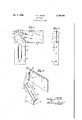
- FIG. 1 is a fragmentary, side view in elevation of a try square illustrationating features of the invention
- Fig. 2 is an edge view of the try square shown in Fig. 1 looking from the end of the blade toward the stock;
- Fig. 3 is a fragmentary view on an enlarged scale of the stock and blade relatively separated.
- 5 indicates a stock or handle preferably made of wood, such as cocobolo or other suitable material.
- the stock is centrally slotted at the top for the reception of the steel blade 6 which fits in the slot and is held in place by a plurality of rivets I passing through registering apertures in the blade and stock and riveted in place so as to hold the stock and blade in the desired right angle relationship.
- the upper edge of the stock is cut on an angle of 45 or beveled, as indicated at 8, and as is also common in try squares as heretofore made.
- a trim plate in the form of a strip of metal 9, such as brass extends along the inside edge of the stock and along the beveled edge 8 on opposite sides of and closely embracing the opposite side surfaces of the metal blade 6.
- screws Ill-l0 for holding the trim in place as indicated in the drawing.
- screws Ill-l0 for holding the trim in place as indicated in the drawing.
- the split end of the trim defining the opposite leg surfaces ll-ll to the wooden stock by means of screws.
- Such method of holding the legs I l-H in place is disadvantageous in that the wood beneath the legs ll-Il is quite thin (being split for the reception of the blade) and there is likelihood of splitting of the woodvor a general weakening of the entire stock.
- My invention is directed particularly to improved means for holding the upper end of the trim plate securely in place without weakening the slotted end of the stock and to avoid the expense of drilling the slotted end of the trim and stock for the reception of screws and the labor and expense of putting the screws in place.
- the trim 9 is slotted along the beveled edge, as indicated at [2, such slot registering with the blade receiving slot in the upper end of the stock 5.
- the slot I2 is a closed slot, while an aligned slot 13 in the free end of the trim may extend all the way to the upper edge thereof.
- an unslotted portion of the trim forms a holding or abutment surface or bridge I4.
- the blade 6 is provided with a transverse slot l5 of a width sufficient to permit the side walls to straddle said bridge.
- the blade slot is of such depth and shape that the upper end It; will fit over and engage flat surface of said bridge I4 so as to. force the trim snugly against the beveled end of the wood stock.
- transverse rivets 1-1 are used to secure the parts firmly together.
- the bridge I4 performs the double function of connecting the relatively narrow legs of the slotted end of the trim and also furnishing an abutment for the trim holding shoulder Hi.
- l of the trim on opposite sides of the blade may be perfectly smooth and will not be interrupted by screws now often used for holding such trim in place.
- the trim will be rigidly held so long as the blade 6 is held to the stock. There are no separate trim screws along the beveled edge to weaken the stock or loosen and permit the trim to get loose.
- a try square including a stock and blade, means for holding said stock and blade together, a trim plate for the face and blade end of said stock, said blade and trim plate having mutually abutting surfaces for holding one end of said trim plate in place adjacent the end of said stock and the balance of said trim. plate against the face of said stock.
- a try square having a stock with a slot therein, a metal blade to fit within said slot. means for holding said blade and stock in assembled relationship, a trim plate one end of said trim plate having two alined slots separated by a bridge, said blade having a slot therein to pass over said bridge, the bottom edge of said slot in said blade being engaged with said bridge on said trim plate for holding the slotted end of the latter in place against the end of said stock.
- a try square including a stock having a beveled upper edge, a slot in said stock, a blade to be positioned in said slot, a trim plate extending over said beveled upper edge and having two alined slots registering with said slot in said stock, said trim plate having a bridge separating said slots, said blade having a transverse slot therein the side walls thereof straddling said bridge, the bottom of the slot in said blade being formed on an angle to fit fiatwise against said bridge on said trim plate for holding the slotted end of the latter rigidly against the beveled end of said stock, and means for rigidly securing said blade in place on said stock.
- a try square including a wooden stock having a beveled upper edge, a slot in the upper end of said stock, a trim plate extending along the inner edge of said stock-and along the beveled upper edge thereof, said trim plate having a closed slot registering with a part of said slot in said stock, said trim plate having a second slot spaced from but in alignment with the first mentioned slot in said trim plate and in alignment with said slot in said stock, said slots in said trim plate defining an abutment surface bridging the slot in said stock, a blade to fit within said slots, said blade having a transversely extending slot therein the side walls thereof straddling said bridging abutment between said slots in said trim plate, the bottom of the slot in said blade bein beveled so as to engage said bridging abutment surface for holding the end of said trim plate in place against the beveled end of said stock, and means for rigidly securing said blade to said stock, for the purpose described.
- a stock having a side face and. an oblique beveled end, said beveled end having two spaced longitudinal slots therein, a blade having a slot to receive that part of the stock between said slots, a trim plate overstanding the face of said stock and having a portion also overstanding the beveled end of the stock, said trim plate having slots registering with the slots in the stock end to receive those portions of the blade adjacent to the slot in the latter.
Landscapes
- Physics & Mathematics (AREA)
- General Physics & Mathematics (AREA)
- Knives (AREA)
Description
w. H. MOHR Dec. 6, 1938.
TRY SQUARE Filed April 6, 1938 INVENTOR ATTORNEYS Patented Dec. 6, 1938 UNITED STATES PATENT OFFICE Application April 6, 1938, Serial No. 200,302
5 Claims.
My invention relates to a try square and more particularly to means for holding a metal or other trim in place.
Try squares as now commonly manufactured 5 have a wooden stock or handle which is slotted to receive a metal blade held in place by rivets or the like passing through registering openings in the blade and handle or stock. In order to maintain the accuracy of such a try square, the stock or handle is often faced with a brass or other trim plate on the inside and when the square is arranged with a beveled edge on the stock the trim extends up along the bevel to the upper outside edge of the stock. The metal trim heretofore has usually been held in place by screws passing through the trim and taking into the wooden stock. In order to hold the split end of the trim embracing the blade and extending along the angle or bevel of the stock in place it has been usual to employ screws extending through the trim and into the wood stock, at least one such screw being located on each side of the metal blade.
It is the principal object of my invention to provide an improved try square having a trim plate, with improved means for holding the trim in place.
It is a further object to provide an improved try square having simplified, cheap means for simultaneously holding the blade and stock together and a trim plate in place.
Other minor objects and various features of invention will be hereinafter pointed out or will become apparent to those skilled in the art.
In the drawing showing a preferred form only of the invention- Fig. 1 is a fragmentary, side view in elevation of a try square ilustrating features of the invention;
Fig. 2 is an edge view of the try square shown in Fig. 1 looking from the end of the blade toward the stock;
Fig. 3 is a fragmentary view on an enlarged scale of the stock and blade relatively separated.
In said drawing, 5 indicates a stock or handle preferably made of wood, such as cocobolo or other suitable material. As is common in try squares, the stock is centrally slotted at the top for the reception of the steel blade 6 which fits in the slot and is held in place by a plurality of rivets I passing through registering apertures in the blade and stock and riveted in place so as to hold the stock and blade in the desired right angle relationship.
In the form shown, the upper edge of the stock is cut on an angle of 45 or beveled, as indicated at 8, and as is also common in try squares as heretofore made. In order to reduce wear on the stock 5 and maintain the accuracy of the square a trim plate in the form of a strip of metal 9, such as brass, extends along the inside edge of the stock and along the beveled edge 8 on opposite sides of and closely embracing the opposite side surfaces of the metal blade 6. Heretofore it has been common to employ a metal trim on a wooden stock and it has been usual to employ screws Ill-l0 for holding the trim in place as indicated in the drawing. It has also been common to secure the split end of the trim defining the opposite leg surfaces ll-ll to the wooden stock by means of screws. Such method of holding the legs I l-H in place is disadvantageous in that the wood beneath the legs ll-Il is quite thin (being split for the reception of the blade) and there is likelihood of splitting of the woodvor a general weakening of the entire stock.
My invention is directed particularly to improved means for holding the upper end of the trim plate securely in place without weakening the slotted end of the stock and to avoid the expense of drilling the slotted end of the trim and stock for the reception of screws and the labor and expense of putting the screws in place.
As shown particularly in Fig. 3, the trim 9 is slotted along the beveled edge, as indicated at [2, such slot registering with the blade receiving slot in the upper end of the stock 5. It will be noted that the slot I2 is a closed slot, while an aligned slot 13 in the free end of the trim may extend all the way to the upper edge thereof. Between the two slots Ill-l3 an unslotted portion of the trim forms a holding or abutment surface or bridge I4. The blade 6 is provided with a transverse slot l5 of a width sufficient to permit the side walls to straddle said bridge. The blade slot is of such depth and shape that the upper end It; will fit over and engage flat surface of said bridge I4 so as to. force the trim snugly against the beveled end of the wood stock. When the blade 6 is seated in place transverse rivets 1-1 are used to secure the parts firmly together. The bridge I4 performs the double function of connecting the relatively narrow legs of the slotted end of the trim and also furnishing an abutment for the trim holding shoulder Hi.
It will be noted that with my improved means for holding the end of the metal trim against the beveled stock end, the legs H--|l of the trim on opposite sides of the blade may be perfectly smooth and will not be interrupted by screws now often used for holding such trim in place. The trim will be rigidly held so long as the blade 6 is held to the stock. There are no separate trim screws along the beveled edge to weaken the stock or loosen and permit the trim to get loose.
It will be seen that, with my improved means, the cost of the parts and the operations of putting the parts together will be less than the cost of assembling similar parts according to conventional methods and the trim will be more securely held and the appearance of the device will be greatly enhanced and the usefulness of the trim will continue so long as the stock and blade remain assembled.
While the invention has been described in considerable detail, it is to be understood that various changes may be made and that my improved means for holding the trim in place is not necessarily limited to the holding of the trim along the beveled edge, since'by a slight modification within the skill of the mechanic the blade and rivet may be employed for holding the trim in place in the region of the blade Whether or not the stock is beveled at the upper end.
, I claim:
1. A try square, including a stock and blade, means for holding said stock and blade together, a trim plate for the face and blade end of said stock, said blade and trim plate having mutually abutting surfaces for holding one end of said trim plate in place adjacent the end of said stock and the balance of said trim. plate against the face of said stock.
2. A try square having a stock with a slot therein, a metal blade to fit within said slot. means for holding said blade and stock in assembled relationship, a trim plate one end of said trim plate having two alined slots separated by a bridge, said blade having a slot therein to pass over said bridge, the bottom edge of said slot in said blade being engaged with said bridge on said trim plate for holding the slotted end of the latter in place against the end of said stock.
3. A try square, including a stock having a beveled upper edge, a slot in said stock, a blade to be positioned in said slot, a trim plate extending over said beveled upper edge and having two alined slots registering with said slot in said stock, said trim plate having a bridge separating said slots, said blade having a transverse slot therein the side walls thereof straddling said bridge, the bottom of the slot in said blade being formed on an angle to fit fiatwise against said bridge on said trim plate for holding the slotted end of the latter rigidly against the beveled end of said stock, and means for rigidly securing said blade in place on said stock.
4. A try square, including a wooden stock having a beveled upper edge, a slot in the upper end of said stock, a trim plate extending along the inner edge of said stock-and along the beveled upper edge thereof, said trim plate having a closed slot registering with a part of said slot in said stock, said trim plate having a second slot spaced from but in alignment with the first mentioned slot in said trim plate and in alignment with said slot in said stock, said slots in said trim plate defining an abutment surface bridging the slot in said stock, a blade to fit within said slots, said blade having a transversely extending slot therein the side walls thereof straddling said bridging abutment between said slots in said trim plate, the bottom of the slot in said blade bein beveled so as to engage said bridging abutment surface for holding the end of said trim plate in place against the beveled end of said stock, and means for rigidly securing said blade to said stock, for the purpose described.
5. In a try square, a stock having a side face and. an oblique beveled end, said beveled end having two spaced longitudinal slots therein, a blade having a slot to receive that part of the stock between said slots, a trim plate overstanding the face of said stock and having a portion also overstanding the beveled end of the stock, said trim plate having slots registering with the slots in the stock end to receive those portions of the blade adjacent to the slot in the latter.
WILLIAM H. MOI-IR.
Priority Applications (1)
| Application Number | Priority Date | Filing Date | Title |
|---|---|---|---|
| US200302A US2139243A (en) | 1938-04-06 | 1938-04-06 | Try square |
Applications Claiming Priority (1)
| Application Number | Priority Date | Filing Date | Title |
|---|---|---|---|
| US200302A US2139243A (en) | 1938-04-06 | 1938-04-06 | Try square |
Publications (1)
| Publication Number | Publication Date |
|---|---|
| US2139243A true US2139243A (en) | 1938-12-06 |
Family
ID=22741137
Family Applications (1)
| Application Number | Title | Priority Date | Filing Date |
|---|---|---|---|
| US200302A Expired - Lifetime US2139243A (en) | 1938-04-06 | 1938-04-06 | Try square |
Country Status (1)
| Country | Link |
|---|---|
| US (1) | US2139243A (en) |
Cited By (3)
| Publication number | Priority date | Publication date | Assignee | Title |
|---|---|---|---|---|
| US2675623A (en) * | 1949-08-26 | 1954-04-20 | Armstrong Cork Co | Device for measuring the thickness of a wet film |
| US20090139104A1 (en) * | 2007-11-30 | 2009-06-04 | Rohweder Barry L | Multi-piece framing square |
| EP4435373A1 (en) * | 2023-03-21 | 2024-09-25 | Hultafors Group AB | Method of manufacturing a fixed square |
-
1938
- 1938-04-06 US US200302A patent/US2139243A/en not_active Expired - Lifetime
Cited By (5)
| Publication number | Priority date | Publication date | Assignee | Title |
|---|---|---|---|---|
| US2675623A (en) * | 1949-08-26 | 1954-04-20 | Armstrong Cork Co | Device for measuring the thickness of a wet film |
| US20090139104A1 (en) * | 2007-11-30 | 2009-06-04 | Rohweder Barry L | Multi-piece framing square |
| EP4435373A1 (en) * | 2023-03-21 | 2024-09-25 | Hultafors Group AB | Method of manufacturing a fixed square |
| US20240316702A1 (en) * | 2023-03-21 | 2024-09-26 | Hultafors Group Ab | Method of manufacturing a fixed square |
| US12151323B2 (en) * | 2023-03-21 | 2024-11-26 | Hultafors Group Ab | Method of manufacturing a fixed square |
Similar Documents
| Publication | Publication Date | Title |
|---|---|---|
| US3090086A (en) | Tapered dove-tail joints | |
| US1954242A (en) | Dovetail spring joint | |
| US1967479A (en) | Tool | |
| US2258326A (en) | Screwhead | |
| US2139243A (en) | Try square | |
| US2422367A (en) | Mortising gauge | |
| US1742201A (en) | Screw clamp | |
| US877879A (en) | Templet. | |
| US1485571A (en) | Knife handle | |
| US2569532A (en) | Joining device | |
| US2410572A (en) | Cutlery | |
| US3976271A (en) | Cutting tool | |
| US2361256A (en) | Handle for saws and the like | |
| GB337997A (en) | Means for jointing parts of furniture | |
| US1931926A (en) | Floor scraper | |
| US2213095A (en) | Plane iron | |
| US1729092A (en) | Tenon saw | |
| US2246260A (en) | Try square | |
| US1587254A (en) | Plasterer's hawk | |
| US1662005A (en) | Carpenter's plane | |
| US2028353A (en) | Frame corner structure | |
| US1725448A (en) | Frame | |
| US2669267A (en) | Handsaw with parallel blades | |
| US2437426A (en) | Tool handle fastening | |
| US1327652A (en) | Die and method of joining its ends |