US2139056A - Floor rack for reerigerator cars - Google Patents
Floor rack for reerigerator cars Download PDFInfo
- Publication number
- US2139056A US2139056A US167405A US16740537A US2139056A US 2139056 A US2139056 A US 2139056A US 167405 A US167405 A US 167405A US 16740537 A US16740537 A US 16740537A US 2139056 A US2139056 A US 2139056A
- Authority
- US
- United States
- Prior art keywords
- floor
- rack
- flanges
- slots
- peripherical
- Prior art date
- Legal status (The legal status is an assumption and is not a legal conclusion. Google has not performed a legal analysis and makes no representation as to the accuracy of the status listed.)
- Expired - Lifetime
Links
- 239000003507 refrigerant Substances 0.000 description 7
- 230000000284 resting effect Effects 0.000 description 5
- 238000010276 construction Methods 0.000 description 2
- 206010022000 influenza Diseases 0.000 description 1
- 238000004519 manufacturing process Methods 0.000 description 1
- 230000004048 modification Effects 0.000 description 1
- 238000012986 modification Methods 0.000 description 1
- 229920000136 polysorbate Polymers 0.000 description 1
- 230000000979 retarding effect Effects 0.000 description 1
- 239000007787 solid Substances 0.000 description 1
- 238000003892 spreading Methods 0.000 description 1
- 238000003860 storage Methods 0.000 description 1
- 238000003466 welding Methods 0.000 description 1
Images

Classifications
-
- B—PERFORMING OPERATIONS; TRANSPORTING
- B61—RAILWAYS
- B61D—BODY DETAILS OR KINDS OF RAILWAY VEHICLES
- B61D27/00—Heating, cooling, ventilating, or air-conditioning
- B61D27/0018—Air-conditioning means, i.e. combining at least two of the following ways of treating or supplying air, namely heating, cooling or ventilating
- B61D27/0027—Air-conditioning means, i.e. combining at least two of the following ways of treating or supplying air, namely heating, cooling or ventilating for freight cars; Isothermic wagons
Definitions
- the object of the invention is to provide a floor rack for a refrigerator car which is very strong l5 to support vertical loads and has great strength in a horizontal direction (to resist the tendency of a shifting load to move the floor rack sidewise) without materially retarding the ilow of air below the iloor rack or materially reducing the amount of air flow through the floor rack.
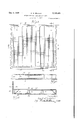
- Figs. 1 and 2 show the corelation of my device to the other elements of a refrigerator car.
- Fig. 3 shows a plan view of one of my improved 26 floor racks.
- Fig. 4 is a section on line 4 4 of Fig. 3.V
- Fig. 5 is a section on line 5-5 of Fig. 3.
- Fig. 6 shows a modved construction of iloor rack.
- Fig. 7 is a section on line 1--1 of Fig. 6.
- the refrigerator car is provided with a bulkhead 2 separating the refrigerant chamber 3 from the lading compartment 4.
- the bulkhead 2 is provided with an aperture 5 adjacent the oor 6 of the car and an aperture 1 adjacent the ceiling 8 of the car with a solid wall 9 therebetween.
- a refrigerant is supported by the grates I2 in the refrigerant chamber 3 in spaced relation to the floor 6 of the car and the basket (or netting) I3 spaces the refrigerant from the end wall I4 and bulkhead 2 to provide the fiues I6-I1.
- the apertured iloor rack I8 supports the lading so as to provide the space 20 which communicates with the fiues IIS-I1.
- a refrigerant, such as ice, in the refrigerant chamber induces a convection circulationof air from the flues I6-I'I through the flue space 20 and the apertures 2I in the floor rack I8, and as the air is warmed by thelading, it rises and passes through the bulkhead upper opening 1, and thence through the ilues I6-I'I, and being cooled by the refrigerant, repeats the convection cycle.
- 'I'he floor rack I3 comprises a metallic sheet formed with depending marginalV flanges 23 which rest upon the floor 6 of the car to support the metallic sheet in spaced relation to the floor to provide the flue 20. These marginal flanges may be bent to form the reilange 24.
- the metallic sheet is provided with a plurality of parallel slots 26 extending preferably continuously between the .marginal flanges 23 through vwhich the circulat ⁇ ing air passes to contact the lading.
- Each of the slots 26 is formed with a preferably continuous peripherical depending flange 21 which stiffens the metallic plate.
- These peripherical flanges 21 constitute a series of beams between the supports or marginal flanges 23. If it were not for these peripherical flanges 21 the edges of the slots 26 would become bent and distorted and cause the surface of the rack to become very rough.
- the Stringer 30 supports the metallic plate be-v tween the marginal flanges 23 and is formed so that the bottom thereof rests upon the floor 6 of the car and the top thereof supports and is preferably secured to the peripherical flanges 21 around the slots 26.
- the beams formed by the peripherical flanges
- 'I'he form of Stringer shown comprises an upper wall 3
- is preferably Welded (34) to the peripherical flanges 21.
- the braces 35 prevent the depending flanges 23 from collapsing under load and comprise a strap secured to a marginal flange 23 adjacent the floor of the car with the other end thereof secured to the metallic plate between the slots 26 and preferably adjacent the peripherical flanges 21.
- the rack comprises a pair of metallic sheets 4I) having their meeting portions joined together (preferably by welding) to form an integral unit, preferably by flanges 4I.
- the slots 42 extend uninterruptedly between the marginal flanges 43 across the joint 44 between the sheets.
- the parts 4I of the meeting edges of the metallic sheets are preferably bent downwardly to form feet which rest upon the floor 6 of the car.
- the racks are hinged (45) to a wall 46 of the car so as to be swung upwardly to clear the floor of the car.
- the stringers 30 and marginal flanges 23 are preferably positioned parallel to the direction of movement of the circulating air in the space 20.
- a rack to support a lading in spaced relation to said ⁇ hoor to provide a flue therebetween, and means to induce an air current in said flue
- said rack comprising a metallic sheet formed with depending marginal flanges resting upon said floor, said sheet provided with a plurality of parallel slots extending substantially between said flanges, each of said slots being provided with a peripherical flange which forms parts of a plurality of parallel inverted channel shaped members integral with said sheet, and a stringer extending normally to said slots with the bottom thereof resting upon said floor and the top thereof secured to a plurality of said peripherical flanges.
- a rack to support a lading in spaced relation to said floor to provide a flue therebetween, and means to induce an air current in said flue
- said rack comprising a metallic sheet formed with depending marginal flanges resting upon said oor, said sheet provided with a plurality of parallel slots extending substantially between said flanges, each of said slots being provided with a peripherical flange which forms parts of a Aplurality of parallel inverted channel shaped members integral with said sheet, and a brace having one end thereof secured to one marginal flange adjacent said floor and the other end thereof secured to said metallic sheet between said parallel slots.
- a rack to support a lading in spaced relation to said floor to provide a ilue therebetween, and means to induce an air current in said flue, said rack comprising a metallic sheet formed with depending marginal flanges resting upon said floor, said sheet provided with a plurality of parallel slots extending substantially between said flanges,
- each of said slots being provided with a peripherical flange which forms parts of a plurality of parallel inverted channel shaped members integral with said sheet, a stringer extending normally to said slots with the bottom thereof resting upon said floor and the top thereof secured to a plurality of said peripherical anges, and a brace having one end thereof secured to one marginal flange adjacent said floor and the other end thereof secured to said metallic sheet between said parallel slots.
- a rack to support a lading in spaced relation to said floor to provide a fiue therebetween, and means to induce an air current in said ue, said rack comprising a pair of metallic sheets joined together to form an integral unit and formed with depending flanges at opposite margins thereof which rest upon said floor, said unit provided with a plurality of parallel slots extending uninterruptedly between said marginal flanges across the joint of the sheets, each of said slots being provided with a peripherical flange which forms parts of a plurality of parallel inverted channel shaped members integral with said sheet.
- a rack to support a. lading in spaced relation to said floor to provide a ue therebetween, and means to induce an air current in said flue, said rack comprising a pair of metallic sheets joined together to form an integral unit and formed with depending flanges at opposite margins thereof which rest upon said floor, said unit provided with a plurality of parallel slots extending uninterruptedly between said marginal flanges across the joint of the sheets, each of said slots being provided with a peripherical flange which forms parts of a plurality of parallel inverted channel shaped members integral with said sheet, the parts of said meeting portions between said slots being bent downwardly to engage said floor.
Landscapes
- Engineering & Computer Science (AREA)
- Mechanical Engineering (AREA)
- Cold Air Circulating Systems And Constructional Details In Refrigerators (AREA)
Description
De@e T1938 K. E. zEmLER FLOOR RACK FOR REFRIGERATOR CARS 2 ShetS-Sheet l Filed Oc't.
1 l l i l l l 1 l 'Aff l 43 K. x-: ZEIDLER 139,056
FLOOR RACK FOR REFRIGERATOR CARS Filed OC.. 5, 1937 2 Sheets- Sheet 2 Patented Dec. 6, 1938 PATENT OFFICE FLOOR RACK FOR RE'PRIGERATOR CARS Kurt E. Zeidler, Pittsburgh, Pa., assigner, by mesne assignments,f to Standard Railway Equipment Manufacturing Company, a corporation of Delaware Application October 5, 1937, Serial No. l167,405
claims.
l() lowecl to get too cold (freeze) or too hot (bake) have4 a high market value because they have a longer storage life.
The object of the invention is to provide a floor rack for a refrigerator car which is very strong l5 to support vertical loads and has great strength in a horizontal direction (to resist the tendency of a shifting load to move the floor rack sidewise) without materially retarding the ilow of air below the iloor rack or materially reducing the amount of air flow through the floor rack.
In thedrawings: Figs. 1 and 2 show the corelation of my device to the other elements of a refrigerator car.
Fig. 3 shows a plan view of one of my improved 26 floor racks.
Fig. 4 is a section on line 4 4 of Fig. 3.V
Fig. 5 is a section on line 5-5 of Fig. 3.
Fig. 6 shows a modiiled construction of iloor rack.
Fig. 7 is a section on line 1--1 of Fig. 6.
In the form of my invention illustrated the refrigerator car is provided with a bulkhead 2 separating the refrigerant chamber 3 from the lading compartment 4. The bulkhead 2 is provided with an aperture 5 adjacent the oor 6 of the car and an aperture 1 adjacent the ceiling 8 of the car with a solid wall 9 therebetween.
A refrigerant is supported by the grates I2 in the refrigerant chamber 3 in spaced relation to the floor 6 of the car and the basket (or netting) I3 spaces the refrigerant from the end wall I4 and bulkhead 2 to provide the fiues I6-I1. The apertured iloor rack I8 supports the lading so as to provide the space 20 which communicates with the fiues IIS-I1. A refrigerant, such as ice, in the refrigerant chamber induces a convection circulationof air from the flues I6-I'I through the flue space 20 and the apertures 2I in the floor rack I8, and as the air is warmed by thelading, it rises and passes through the bulkhead upper opening 1, and thence through the ilues I6-I'I, and being cooled by the refrigerant, repeats the convection cycle.
'I'he floor rack I3 comprises a metallic sheet formed with depending marginalV flanges 23 which rest upon the floor 6 of the car to support the metallic sheet in spaced relation to the floor to provide the flue 20. These marginal flanges may be bent to form the reilange 24. The metallic sheet is provided with a plurality of parallel slots 26 extending preferably continuously between the .marginal flanges 23 through vwhich the circulat` ing air passes to contact the lading. Each of the slots 26 is formed with a preferably continuous peripherical depending flange 21 which stiffens the metallic plate. These peripherical flanges 21 constitute a series of beams between the supports or marginal flanges 23. If it were not for these peripherical flanges 21 the edges of the slots 26 would become bent and distorted and cause the surface of the rack to become very rough.
The Stringer 30 supports the metallic plate be-v tween the marginal flanges 23 and is formed so that the bottom thereof rests upon the floor 6 of the car and the top thereof supports and is preferably secured to the peripherical flanges 21 around the slots 26. In other words, the beams (formed by the peripherical flanges) are supported between their ends. 'I'he form of Stringer shown comprises an upper wall 3| between diverging legs 32 which are prevented from spreading by a strap 33. The upper wall 3| is preferably Welded (34) to the peripherical flanges 21.
The braces 35 prevent the depending flanges 23 from collapsing under load and comprise a strap secured to a marginal flange 23 adjacent the floor of the car with the other end thereof secured to the metallic plate between the slots 26 and preferably adjacent the peripherical flanges 21.
In the form'shown in Figs. 6 and '7 the rack comprises a pair of metallic sheets 4I) having their meeting portions joined together (preferably by welding) to form an integral unit, preferably by flanges 4I. The slots 42 extend uninterruptedly between the marginal flanges 43 across the joint 44 between the sheets. The parts 4I of the meeting edges of the metallic sheets are preferably bent downwardly to form feet which rest upon the floor 6 of the car.
In the arrangement shown the racks are hinged (45) to a wall 46 of the car so as to be swung upwardly to clear the floor of the car. The stringers 30 and marginal flanges 23 are preferably positioned parallel to the direction of movement of the circulating air in the space 20.
The accompanying drawings illustrate the preferred form of the invention, though it is to be understood that the invention is not limited to the exact details of construction shown and described, as it is obvious that various modifications thereof, within the scope of the claims, will occur to persons skilled in the art.
I claim:
l. In a refrigerator car having a floor, a rack to support a lading in spaced relation to said `hoor to provide a flue therebetween, and means to induce an air current in said flue, said rack comprising a metallic sheet formed with depending marginal flanges resting upon said floor, said sheet provided with a plurality of parallel slots extending substantially between said flanges, each of said slots being provided with a peripherical flange which forms parts of a plurality of parallel inverted channel shaped members integral with said sheet, and a stringer extending normally to said slots with the bottom thereof resting upon said floor and the top thereof secured to a plurality of said peripherical flanges.
2. In a refrigerator car having a floor, a rack to support a lading in spaced relation to said floor to provide a flue therebetween, and means to induce an air current in said flue, said rack comprising a metallic sheet formed with depending marginal flanges resting upon said oor, said sheet provided with a plurality of parallel slots extending substantially between said flanges, each of said slots being provided with a peripherical flange which forms parts of a Aplurality of parallel inverted channel shaped members integral with said sheet, and a brace having one end thereof secured to one marginal flange adjacent said floor and the other end thereof secured to said metallic sheet between said parallel slots.
3. In a refrigerator car having a floor, a rack to support a lading in spaced relation to said floor to provide a ilue therebetween, and means to induce an air current in said flue, said rack comprising a metallic sheet formed with depending marginal flanges resting upon said floor, said sheet provided with a plurality of parallel slots extending substantially between said flanges,
each of said slots being provided with a peripherical flange which forms parts of a plurality of parallel inverted channel shaped members integral with said sheet, a stringer extending normally to said slots with the bottom thereof resting upon said floor and the top thereof secured to a plurality of said peripherical anges, and a brace having one end thereof secured to one marginal flange adjacent said floor and the other end thereof secured to said metallic sheet between said parallel slots.
4. In a refrigerator car having a door, a rack to support a lading in spaced relation to said floor to provide a fiue therebetween, and means to induce an air current in said ue, said rack comprising a pair of metallic sheets joined together to form an integral unit and formed with depending flanges at opposite margins thereof which rest upon said floor, said unit provided with a plurality of parallel slots extending uninterruptedly between said marginal flanges across the joint of the sheets, each of said slots being provided with a peripherical flange which forms parts of a plurality of parallel inverted channel shaped members integral with said sheet.
5. In a refrigerator car having a floor, a rack to support a. lading in spaced relation to said floor to provide a ue therebetween, and means to induce an air current in said flue, said rack comprising a pair of metallic sheets joined together to form an integral unit and formed with depending flanges at opposite margins thereof which rest upon said floor, said unit provided with a plurality of parallel slots extending uninterruptedly between said marginal flanges across the joint of the sheets, each of said slots being provided with a peripherical flange which forms parts of a plurality of parallel inverted channel shaped members integral with said sheet, the parts of said meeting portions between said slots being bent downwardly to engage said floor.
KURT E. ZEIDLER.
Priority Applications (1)
| Application Number | Priority Date | Filing Date | Title |
|---|---|---|---|
| US167405A US2139056A (en) | 1937-10-05 | 1937-10-05 | Floor rack for reerigerator cars |
Applications Claiming Priority (1)
| Application Number | Priority Date | Filing Date | Title |
|---|---|---|---|
| US167405A US2139056A (en) | 1937-10-05 | 1937-10-05 | Floor rack for reerigerator cars |
Publications (1)
| Publication Number | Publication Date |
|---|---|
| US2139056A true US2139056A (en) | 1938-12-06 |
Family
ID=22607243
Family Applications (1)
| Application Number | Title | Priority Date | Filing Date |
|---|---|---|---|
| US167405A Expired - Lifetime US2139056A (en) | 1937-10-05 | 1937-10-05 | Floor rack for reerigerator cars |
Country Status (1)
| Country | Link |
|---|---|
| US (1) | US2139056A (en) |
-
1937
- 1937-10-05 US US167405A patent/US2139056A/en not_active Expired - Lifetime
Similar Documents
| Publication | Publication Date | Title |
|---|---|---|
| US2456481A (en) | Rigid lightweight metal tray | |
| US2180502A (en) | Refrigerator car floor rack | |
| US2139056A (en) | Floor rack for reerigerator cars | |
| US2162361A (en) | Refrigerator car floor rack | |
| US2231208A (en) | Floor rack for refrigerator cars | |
| US2188851A (en) | Refrigerator car floor rack | |
| US2147130A (en) | Floor rack for refrigerator cars | |
| US2188171A (en) | Floor rack for refrigerator cars | |
| US2214547A (en) | Floor rack for refrigeration cars | |
| US2229547A (en) | Floor rack for refrigerator cars | |
| US2168595A (en) | Refrigerator car floor rack | |
| US2256197A (en) | Refrigerator car | |
| US2188852A (en) | Floor rack for refrigerator cars | |
| US2256180A (en) | Floor rack for refrigerator vehicles | |
| US2242938A (en) | Top bunker refrigerator car | |
| US2279545A (en) | Floor rack | |
| US2147131A (en) | Floor rack for refrigerator cars | |
| US2187219A (en) | Floor rack for refrigerator cars | |
| US2139043A (en) | Floor rack stringer | |
| US2139044A (en) | Refrigerator car floor rack | |
| US2313120A (en) | Refrigerator car | |
| US2178739A (en) | Floor rack for refrigerator cars | |
| US2316755A (en) | Refrigerator car | |
| US2312016A (en) | Refrigerator car construction | |
| US2603169A (en) | Floor rack |