US2136992A - Heating structure for drying, ironing, calendering, and similar machines - Google Patents
Heating structure for drying, ironing, calendering, and similar machines Download PDFInfo
- Publication number
- US2136992A US2136992A US69600A US6960036A US2136992A US 2136992 A US2136992 A US 2136992A US 69600 A US69600 A US 69600A US 6960036 A US6960036 A US 6960036A US 2136992 A US2136992 A US 2136992A
- Authority
- US
- United States
- Prior art keywords
- sheet
- heating structure
- steam
- passages
- flange
- Prior art date
- Legal status (The legal status is an assumption and is not a legal conclusion. Google has not performed a legal analysis and makes no representation as to the accuracy of the status listed.)
- Expired - Lifetime
Links
- 238000010438 heat treatment Methods 0.000 title description 21
- 238000010409 ironing Methods 0.000 title description 5
- 238000003490 calendering Methods 0.000 title description 4
- 238000001035 drying Methods 0.000 title description 4
- 229910000746 Structural steel Inorganic materials 0.000 description 13
- XEEYBQQBJWHFJM-UHFFFAOYSA-N Iron Chemical compound [Fe] XEEYBQQBJWHFJM-UHFFFAOYSA-N 0.000 description 12
- 235000000396 iron Nutrition 0.000 description 10
- 239000002184 metal Substances 0.000 description 7
- 229910052751 metal Inorganic materials 0.000 description 7
- 229910052742 iron Inorganic materials 0.000 description 6
- 238000010276 construction Methods 0.000 description 2
- 230000001419 dependent effect Effects 0.000 description 2
- 239000004744 fabric Substances 0.000 description 2
- 239000012530 fluid Substances 0.000 description 2
- 238000003466 welding Methods 0.000 description 2
- 244000221110 common millet Species 0.000 description 1
- 239000011810 insulating material Substances 0.000 description 1
- 239000000463 material Substances 0.000 description 1
- 239000010409 thin film Substances 0.000 description 1
- XLYOFNOQVPJJNP-UHFFFAOYSA-N water Substances O XLYOFNOQVPJJNP-UHFFFAOYSA-N 0.000 description 1
Images
Classifications
-
- D—TEXTILES; PAPER
- D06—TREATMENT OF TEXTILES OR THE LIKE; LAUNDERING; FLEXIBLE MATERIALS NOT OTHERWISE PROVIDED FOR
- D06F—LAUNDERING, DRYING, IRONING, PRESSING OR FOLDING TEXTILE ARTICLES
- D06F67/00—Details of ironing machines provided for in groups D06F61/00, D06F63/00, or D06F65/00
- D06F67/08—Beds; Heating arrangements therefor
Definitions
- the present invention relates to the construetion and the arrangement of parts of a metallic heating structure, comprising a curved wall shaped in any desired form and a plurality of adjacent longitudinal metallic hollow members with an open side secured to the outer face of said wall so as to form passages adapted to receive heating fluid such as steam under pressure, said metallic hollow members being connected so as to provide for a continuous steam circulation from a steam inlet at one end of said structure to an outlet at the opposite end of said structure.
- heating structures are generally used in ironing, drying, calendering, glazing and other finishing machines or in combined ma-' chines performing several of these operations, which machines are mainly used for the treatment of fabric, paper and the like.
- One object of the invention is to provide a metallic heating structure of the kind described having steam containing passages formed by an arrangement of rolled iron members, whereby each of said steam containing passages is formed by securing a flange of an iron member on said wall and the other flange on the flange of the adjacent iron member.
- Another object of the invention is to provide a metallic heating structure having said steam containing passages formed by rolled angle irons arranged so that said passages are of different cross sectional area according to their distance from the inlet of steam, so that steam circulates in all passages at the same predetermined speed.
- Another object of the invention is to provide a metallic heating structure of the kind described having said steam containing passages formed by rolled angle iron arranged so that a perfect resistance to mechanical strains and a high degree of rigidity of the structure are insured.
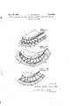
- Fig. 1 is a transverse crosssection of a pora part of a heating structure having steam containing passages of different cross sections.
- Fig. 3 is across section of a portion of a metallic ironing table will be heated, or heat will be di-- heating structure having rolled angle iron members arranged in such a manner that an uniform heat distribution is combined with a high degree of rigidity.
- the improved heating structure comprises a curved metal sheet I and a plurality of adjacent longitudinal metallic hollow members parallel to the axis of said structure and secured to the outer face of said sheet I, said members being open towards said wall so as to "form passages 10 2 adapted to contain heating fluid such as steam under pressure.
- the metallic members are externally covered by heat insulating material 3, so as to avoid loss of heat.
- the steam is admitted into the heating structure through an inlet open- 15 ing not shown and circulates within said passages 2 towards an outlet opening for steam whereby heat is transmitted from the steam to said sheet I, so that air or a roller acting as an 0 rectly transmitted to fabric or other materials treated.
- passages 2 are formed by longitudinal rolled iron members 4 secured to said curved sheet, preferably, by solder- 25 ing or welding, so as to confine between themselves and the metal sheet i a space for circulation of a required amount of steam.
- passages 2 are formed by securing a flange 5 of an angle 30 iron 4 on said sheet I and the other flange 5 on the adjacent flange 5 of the contiguous angle iron 4, so that each passage 2 which is open towards the sheet I is defined by a portion of the curved sheet I and the flanges of two contiguous 35 angle irons 4.
- the amount of heat directly received by the portion of the sheet I which forms one of the walls of a passage 2 is dependent on the amount of steam contained in said passage, which 40 latter amount is dependent upon the cross sectional area of said passage.
- the steam containing passages disposed at a greater distance from the inlet of steam may be of a less cross section than the passages disposed 45 at a less distance from said inlet, so that steam circulates in all passages with the same speed with the result that a thin film of water condensing in said passages is blown away in all passages.
- the invention makes it possible to use rolled angle irons of the same shape and size for constructing a heating structure in which said passages are of a varying cross section according to the heating eflect to be obtained.
- a variation of said cross section is obtained by welding the flange 8 of an angle iron to a different point of the flange 5 of the contiguous angle iron, which point may be more or less distant from the metal sheet i.
- angle irons 4 may be of any desired shape and size. Also all rolled iron members used or only some of them may be arcuate as illustrated in Fig. 2 and a flange 8 of an angle iron may be secured on the corresponding flange 6 of a contiguous angle iron instead of bein fixed to the flange i (Fig. 3).
- the angle irons 2 arranged according to the invention not only form passages for a circulation of steam, but they also greatly increase the strength of the structure in which the outer face of the curved metal sheet I is subjected to the pressure of steam and the inner face thereof is subjected to heavy mechanical strains exerted by, the use of the machine.
- the angle irons 4 together with the metal sheet i form a lattice-girder which increases the rigidity of the metal sheet i, so that pressure of the steam or strains exerted on the inner face thereof may be increased.
- Heating structure for machines of the kind described comprising in combination a curved metallic sheet and a plurality of adjacent longitudinal metallic hollow members secured to the outer face of said sheet and open towards said sheet, said hollow members each being formed by a rolled angle iron having two flanges, one of said flanges being edgewise welded to said curved sheet and the other flange being edgewise welded to the adjacent flange of the adjacent angle iron at a point spaced from the junction of the flanges of the adjacent angle iron.
- Heating structure for machines of the kind described comprising in combination a curved metallic sheet and a plurality of adjacent longitudinal metallic hollow members secured to the outer face of said sheet and open towards said sheet, said hollow members each being formed by one of a set of rolled angle irons of the same shape and size having two flanges, one of said flanges being edgewise welded to said curved sheet and the other flange being welded to the adjacent flange of the adjacent angle iron at a point spaced from the junction of the flanges of the adjacent angle iron, the spacing of said point being different for different members, so that said angle irons are secured in different angular positions with respect to said curved sheet, whereby the portion of said curved sheet in contact with steam circulating is different for different passages.
- Heating structure or machines of thekind described comprising in combination a curved metallic sheet and a plurality of adjacent longitudinal hollow members secured to the outer face of said sheet and open towards said sheet, said hollow members each being formed by one of a set of rolled angle irons of different shape and size and each having two flanges, one of said flanges being edgewise welded to the adjacent flange of the adjacent angle iron and the other flange being welded at a point of the outer wall of said curved metallic sheet, the spacing of points at which two contiguous rolled angle irons are welded to the outer face of said curved metallic sheet being different for different hollow members.
- Heating structure for machines of the kind described comprising in combination a curved metallic sheet and a plurality of adjacent longitudinal metallic hollow members secured to the outer face of said sheet and open towards said sheet, each of said hollow members comprising a metal member consisting of two legs joined together, the portion of said legs adjacent the terminal edges thereof lying in planes at an angle to each other, the terminal edge of one leg engaging and being welded to the curved sheet and the terminal edge of the other leg being welded to an intermediate point of the sheetengaging leg of an adjacent member.
Landscapes
- Engineering & Computer Science (AREA)
- Textile Engineering (AREA)
- General Induction Heating (AREA)
Description
Nov. 15, 1938. H Nss s 2,136,992
AND SIMILAR MACHINES IRONING, CALENDERING,
Filed, March 18, 1936 HEATING STRUCTURE FOR DRYING,
INVENTOR HEYNSSENS N d8) ATTO/F/VEY EON JOSEPH L Patented Nov. 15, 1938 UNITED STATES PATENT OFFICE HEATING STRUCTURE FOR DRYING, IRON- ING, CALENDERING, AND SIMILAR MA- CHINES 4 Claims.
The present invention relates to the construetion and the arrangement of parts of a metallic heating structure, comprising a curved wall shaped in any desired form and a plurality of adjacent longitudinal metallic hollow members with an open side secured to the outer face of said wall so as to form passages adapted to receive heating fluid such as steam under pressure, said metallic hollow members being connected so as to provide for a continuous steam circulation from a steam inlet at one end of said structure to an outlet at the opposite end of said structure. As known, such heating structures are generally used in ironing, drying, calendering, glazing and other finishing machines or in combined ma-' chines performing several of these operations, which machines are mainly used for the treatment of fabric, paper and the like.
One object of the invention is to provide a metallic heating structure of the kind described having steam containing passages formed by an arrangement of rolled iron members, whereby each of said steam containing passages is formed by securing a flange of an iron member on said wall and the other flange on the flange of the adjacent iron member.
Another object of the invention is to provide a metallic heating structure having said steam containing passages formed by rolled angle irons arranged so that said passages are of different cross sectional area according to their distance from the inlet of steam, so that steam circulates in all passages at the same predetermined speed.
Another object of the invention is to provide a metallic heating structure of the kind described having said steam containing passages formed by rolled angle iron arranged so that a perfect resistance to mechanical strains and a high degree of rigidity of the structure are insured.
Other novel features of construction and arrangement of parts of themetallic heating structure according to the invention will appear from the following description of the accompanying drawing whichis however merely intended to diagrammatically illustrate by way of example, the principle of my invention without limiting the scope to the constructions shown.
Fig. 1 is a transverse crosssection of a pora part of a heating structure having steam containing passages of different cross sections.
Fig. 3 is across section of a portion of a metallic ironing table will be heated, or heat will be di-- heating structure having rolled angle iron members arranged in such a manner that an uniform heat distribution is combined with a high degree of rigidity.
The improved heating structure comprises a curved metal sheet I and a plurality of adjacent longitudinal metallic hollow members parallel to the axis of said structure and secured to the outer face of said sheet I, said members being open towards said wall so as to "form passages 10 2 adapted to contain heating fluid such as steam under pressure. The metallic members are externally covered by heat insulating material 3, so as to avoid loss of heat. The steam is admitted into the heating structure through an inlet open- 15 ing not shown and circulates within said passages 2 towards an outlet opening for steam whereby heat is transmitted from the steam to said sheet I, so that air or a roller acting as an 0 rectly transmitted to fabric or other materials treated.
According to the invention said passages 2 are formed by longitudinal rolled iron members 4 secured to said curved sheet, preferably, by solder- 25 ing or welding, so as to confine between themselves and the metal sheet i a space for circulation of a required amount of steam.
In the form shown in the figures said passages 2 are formed by securing a flange 5 of an angle 30 iron 4 on said sheet I and the other flange 5 on the adjacent flange 5 of the contiguous angle iron 4, so that each passage 2 which is open towards the sheet I is defined by a portion of the curved sheet I and the flanges of two contiguous 35 angle irons 4.
As known the amount of heat directly received by the portion of the sheet I which forms one of the walls of a passage 2 is dependent on the amount of steam contained in said passage, which 40 latter amount is dependent upon the cross sectional area of said passage. On the other hand, the steam containing passages disposed at a greater distance from the inlet of steam may be of a less cross section than the passages disposed 45 at a less distance from said inlet, so that steam circulates in all passages with the same speed with the result that a thin film of water condensing in said passages is blown away in all passages.
The invention makes it possible to use rolled angle irons of the same shape and size for constructing a heating structure in which said passages are of a varying cross section according to the heating eflect to be obtained. According to 55 the invention such a variation of said cross section is obtained by welding the flange 8 of an angle iron to a different point of the flange 5 of the contiguous angle iron, which point may be more or less distant from the metal sheet i.
It is obvious that said angle irons 4 may be of any desired shape and size. Also all rolled iron members used or only some of them may be arcuate as illustrated in Fig. 2 and a flange 8 of an angle iron may be secured on the corresponding flange 6 of a contiguous angle iron instead of bein fixed to the flange i (Fig. 3).
The angle irons 2 arranged according to the invention not only form passages for a circulation of steam, but they also greatly increase the strength of the structure in which the outer face of the curved metal sheet I is subjected to the pressure of steam and the inner face thereof is subjected to heavy mechanical strains exerted by, the use of the machine. The angle irons 4 together with the metal sheet i form a lattice-girder which increases the rigidity of the metal sheet i, so that pressure of the steam or strains exerted on the inner face thereof may be increased.
Having now particularly described and ascertained the nature of my invention and in what manner the same is to be performed, I declare that what I claim is:
1. Heating structure for machines of the kind described comprising in combination a curved metallic sheet and a plurality of adjacent longitudinal metallic hollow members secured to the outer face of said sheet and open towards said sheet, said hollow members each being formed by a rolled angle iron having two flanges, one of said flanges being edgewise welded to said curved sheet and the other flange being edgewise welded to the adjacent flange of the adjacent angle iron at a point spaced from the junction of the flanges of the adjacent angle iron.
2. Heating structure for machines of the kind described comprising in combination a curved metallic sheet and a plurality of adjacent longitudinal metallic hollow members secured to the outer face of said sheet and open towards said sheet, said hollow members each being formed by one of a set of rolled angle irons of the same shape and size having two flanges, one of said flanges being edgewise welded to said curved sheet and the other flange being welded to the adjacent flange of the adjacent angle iron at a point spaced from the junction of the flanges of the adjacent angle iron, the spacing of said point being different for different members, so that said angle irons are secured in different angular positions with respect to said curved sheet, whereby the portion of said curved sheet in contact with steam circulating is different for different passages.
3. Heating structure or machines of thekind described comprising in combination a curved metallic sheet and a plurality of adjacent longitudinal hollow members secured to the outer face of said sheet and open towards said sheet, said hollow members each being formed by one of a set of rolled angle irons of different shape and size and each having two flanges, one of said flanges being edgewise welded to the adjacent flange of the adjacent angle iron and the other flange being welded at a point of the outer wall of said curved metallic sheet, the spacing of points at which two contiguous rolled angle irons are welded to the outer face of said curved metallic sheet being different for different hollow members.
4. Heating structure for machines of the kind described comprising in combination a curved metallic sheet and a plurality of adjacent longitudinal metallic hollow members secured to the outer face of said sheet and open towards said sheet, each of said hollow members comprising a metal member consisting of two legs joined together, the portion of said legs adjacent the terminal edges thereof lying in planes at an angle to each other, the terminal edge of one leg engaging and being welded to the curved sheet and the terminal edge of the other leg being welded to an intermediate point of the sheetengaging leg of an adjacent member.
JOSEPH LEON HEYNSSENS.
Priority Applications (1)
| Application Number | Priority Date | Filing Date | Title |
|---|---|---|---|
| US69600A US2136992A (en) | 1936-03-18 | 1936-03-18 | Heating structure for drying, ironing, calendering, and similar machines |
Applications Claiming Priority (1)
| Application Number | Priority Date | Filing Date | Title |
|---|---|---|---|
| US69600A US2136992A (en) | 1936-03-18 | 1936-03-18 | Heating structure for drying, ironing, calendering, and similar machines |
Publications (1)
| Publication Number | Publication Date |
|---|---|
| US2136992A true US2136992A (en) | 1938-11-15 |
Family
ID=22090035
Family Applications (1)
| Application Number | Title | Priority Date | Filing Date |
|---|---|---|---|
| US69600A Expired - Lifetime US2136992A (en) | 1936-03-18 | 1936-03-18 | Heating structure for drying, ironing, calendering, and similar machines |
Country Status (1)
| Country | Link |
|---|---|
| US (1) | US2136992A (en) |
Cited By (3)
| Publication number | Priority date | Publication date | Assignee | Title |
|---|---|---|---|---|
| US2504465A (en) * | 1945-09-06 | 1950-04-18 | Stickelber & Sons Inc | Refrigerated dough mixer |
| US3918893A (en) * | 1974-11-13 | 1975-11-11 | Allis Chalmers | Elongated rotary drum shell construction |
| US4750556A (en) * | 1986-10-29 | 1988-06-14 | Daniel del Valle P. | Reactor apparatus |
-
1936
- 1936-03-18 US US69600A patent/US2136992A/en not_active Expired - Lifetime
Cited By (3)
| Publication number | Priority date | Publication date | Assignee | Title |
|---|---|---|---|---|
| US2504465A (en) * | 1945-09-06 | 1950-04-18 | Stickelber & Sons Inc | Refrigerated dough mixer |
| US3918893A (en) * | 1974-11-13 | 1975-11-11 | Allis Chalmers | Elongated rotary drum shell construction |
| US4750556A (en) * | 1986-10-29 | 1988-06-14 | Daniel del Valle P. | Reactor apparatus |
Similar Documents
| Publication | Publication Date | Title |
|---|---|---|
| CN106222912A (en) | A kind of New drying device | |
| US2932091A (en) | Heated shell drum dryers | |
| US1015404A (en) | Heating or cooling plate. | |
| US1463923A (en) | Pabeb-dbztkg machihe | |
| US1470953A (en) | Paper-making machine | |
| US2057988A (en) | Laundry ironer | |
| US3118743A (en) | Papermaking drier drum | |
| US8561327B2 (en) | Ironer bed | |
| US2065576A (en) | Steamer and preheater for corrugating machines | |
| DE601858C (en) | Steam shrink machine | |
| US2289653A (en) | Ventilating metal ironing table top | |
| US1577509A (en) | Apparatus for handling vapors | |
| DE813340C (en) | Method and device for drying paper in paper machines | |
| US1678383A (en) | Drying machine | |
| SU558554A1 (en) | Squeeze roller | |
| US1638626A (en) | Heating means for rolls | |
| US1032713A (en) | Wool and other fiber drying machine. | |
| US2869258A (en) | Arrangement in calenders | |
| AT122695B (en) | Method and device for drying paper webs. | |
| US427453A (en) | barden | |
| US1769009A (en) | Laundry ironing and pressing apparatus | |
| USRE15362E (en) | By xtebome p | |
| US1834365A (en) | Laundry ironing and pressing apparatus | |
| AT155004B (en) | Dyeing machine. | |
| US107469A (en) | Improvement in ironing-boards |