US2133204A - Fastener - Google Patents
Fastener Download PDFInfo
- Publication number
- US2133204A US2133204A US148623A US14862337A US2133204A US 2133204 A US2133204 A US 2133204A US 148623 A US148623 A US 148623A US 14862337 A US14862337 A US 14862337A US 2133204 A US2133204 A US 2133204A
- Authority
- US
- United States
- Prior art keywords
- fastener
- structural elements
- wing
- anchoring
- piece
- Prior art date
- Legal status (The legal status is an assumption and is not a legal conclusion. Google has not performed a legal analysis and makes no representation as to the accuracy of the status listed.)
- Expired - Lifetime
Links
- 238000004873 anchoring Methods 0.000 description 7
- 239000000463 material Substances 0.000 description 4
- XEEYBQQBJWHFJM-UHFFFAOYSA-N Iron Chemical compound [Fe] XEEYBQQBJWHFJM-UHFFFAOYSA-N 0.000 description 2
- 210000001503 joint Anatomy 0.000 description 2
- 239000002023 wood Substances 0.000 description 2
- 238000010276 construction Methods 0.000 description 1
- 229910052742 iron Inorganic materials 0.000 description 1
- 239000002184 metal Substances 0.000 description 1
- 229910052751 metal Inorganic materials 0.000 description 1
- 230000035515 penetration Effects 0.000 description 1
- 238000005476 soldering Methods 0.000 description 1
Images
Classifications
-
- F—MECHANICAL ENGINEERING; LIGHTING; HEATING; WEAPONS; BLASTING
- F16—ENGINEERING ELEMENTS AND UNITS; GENERAL MEASURES FOR PRODUCING AND MAINTAINING EFFECTIVE FUNCTIONING OF MACHINES OR INSTALLATIONS; THERMAL INSULATION IN GENERAL
- F16B—DEVICES FOR FASTENING OR SECURING CONSTRUCTIONAL ELEMENTS OR MACHINE PARTS TOGETHER, e.g. NAILS, BOLTS, CIRCLIPS, CLAMPS, CLIPS OR WEDGES; JOINTS OR JOINTING
- F16B12/00—Jointing of furniture or the like, e.g. hidden from exterior
- F16B12/44—Leg joints; Corner joints
- F16B12/46—Non-metal corner connections
-
- F—MECHANICAL ENGINEERING; LIGHTING; HEATING; WEAPONS; BLASTING
- F16—ENGINEERING ELEMENTS AND UNITS; GENERAL MEASURES FOR PRODUCING AND MAINTAINING EFFECTIVE FUNCTIONING OF MACHINES OR INSTALLATIONS; THERMAL INSULATION IN GENERAL
- F16B—DEVICES FOR FASTENING OR SECURING CONSTRUCTIONAL ELEMENTS OR MACHINE PARTS TOGETHER, e.g. NAILS, BOLTS, CIRCLIPS, CLAMPS, CLIPS OR WEDGES; JOINTS OR JOINTING
- F16B2200/00—Constructional details of connections not covered for in other groups of this subclass
- F16B2200/69—Redundant disconnection blocking means
-
- Y—GENERAL TAGGING OF NEW TECHNOLOGICAL DEVELOPMENTS; GENERAL TAGGING OF CROSS-SECTIONAL TECHNOLOGIES SPANNING OVER SEVERAL SECTIONS OF THE IPC; TECHNICAL SUBJECTS COVERED BY FORMER USPC CROSS-REFERENCE ART COLLECTIONS [XRACs] AND DIGESTS
- Y10—TECHNICAL SUBJECTS COVERED BY FORMER USPC
- Y10S—TECHNICAL SUBJECTS COVERED BY FORMER USPC CROSS-REFERENCE ART COLLECTIONS [XRACs] AND DIGESTS
- Y10S135/00—Tent, canopy, umbrella, or cane
- Y10S135/909—Fitting
Definitions
- any o'her suitable securing elements may be used for the purpose of the described anchoring.
- the fastening means according to the invention for the assembling of wooden structural elements, has the advantage of extreme simplicity, and permits at any time of the ready assembling and dismantling of structural elements joined together at the corners, more particularly in the case of furniture.
- the invention thus provides a substitute for the usual rigid and permanent assembling of corners by dovetailing.
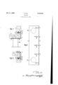
- Fig. 1 shows the corner fastener according to the invention in vertical section.
- Fig. 2 shows the same in piane view with ihe wooden structural elements removed.
- Fig. 3 shows a modiiied form of the fastener in sectional elevation.
- the fastener according to the invention consists of an angle piece I, of metal or other suitable material, adapted to be placed against the corner formed by two abutting wooden structural elements 2, 3, for example theV bottom and side 45 wall of a cabinet.
- the lower ilange or wing 4 of the angle piece is provided, according to the breadth of the elements (boards) to be assembled,
- the screw I A is lscrewed in from the outside through the wing 4 of the angle piece and through the wood ot the board 2, and holds fast both the board 2 and also the board 3 disposed therebeneath. In this manner Y a thoroughly rigid and permanent corner joint. which is nevertheless easily detachable, can be In use the fastening contrivance is- (Cl. 20-92l made with the aid of a small number of screws. After removal of th anchoring screws 1, the piece of furniture or the like may easily be taken apart, and equally easily assembled again later. The lower wing 4 of the angle piece may also at the same time be ⁇ used for the attaching of the feet or legs I0 of the piece of furniture, if such be provided.
- the wing 4 of the angle piece is made somewhat wider than it otherwise need be.
- the fastener is to be used solely for making a corner joint (for instance at theupper corners of a piece of furnilure) it is suiliclent, as shown in Fig. 3, to make the wingvor flange 4 only just wide enoughvto enable the dowel pins 5 to be reliably attached thereto by soldering, weld# ing, or the like.
- the pins 5 may be of round or polygonal crosssection, and if desired may be provided with a pointed tip to .facilitae penetration into the wood. It is advisable to make the holes in the wing 4' of the angle piece so large that the head 9 oi the anchoring screw 1 can be countersunk so that it is not noticeable from the outside.
- a fastener for the detachable joining together of-wooden structural elements', more particularly in furniture comprising a length of angle section material adapted to be applied to the outside of a right angle butt joint, at least oneand an anchoring element adapted to it the said holes and to extend therethrough and through the interveningv portion 'of said structural elements when assembled.
- a fastener for the detachable joining to'- gether ⁇ oiv wooden struc'ural elements, more particularly in furniture comprising a length of angle section material adapted to be applied to the outside of a right angled butt joint, at least one downel pin rigidly attached to the inside of one of the flanges .of said section ⁇ and extending parallel to the other flange of said sec'ion, the outer end portion of said dowel pin being transverselydrilled at right angles to the said ilange disposed parallel there'o, and screw threaded, and the said flange disposed parallel to the said dowel pin being drilled transversely in alignment with said screw threaded hole in said dowel lpin, and countersunk on theouter side, and an anchoring screw adapted to extend through said ⁇ iiange and adjoining structural element and to be screwed into engagement with said threaded hole in said dowel pin.
Description
E. MAX
Oct. 11, 1938.
FASTENER Filed June 16, 1937 Patented Oct. 11, 1938 UNITED STATES PATENT oFFicEj FASTENER Ella Max, Paris, France Application June 16, 1937, Serial No. 148,623 In Austria June 2 0, 1936 2 Claims.
section iron or other suitable material to the. one
flange or wing of which there are attached one or more pins or pegs disposed parallel to the o'her wing and having transverse holes drilled therethrough for the reception of anchoring screws. placed against the corner formed between two structural elements to be assembled, with the said pins exending into sockets drilled to receive them in the structural elements to be assembled; after which anchoring screws are inserted through the transverse holes in the pins to hold the assembly together. Instead of screws, any o'her suitable securing elements may be used for the purpose of the described anchoring.
The fastening means according to the invention, for the assembling of wooden structural elements, has the advantage of extreme simplicity, and permits at any time of the ready assembling and dismantling of structural elements joined together at the corners, more particularly in the case of furniture. The invention thus provides a substitute for the usual rigid and permanent assembling of corners by dovetailing.
A form of construction embodying the invention, is shown, by way of example, diagrammatically, in the accompanying drawing, in which:-
Fig. 1 shows the corner fastener according to the invention in vertical section.
Fig. 2 shows the same in piane view with ihe wooden structural elements removed.
Fig. 3 shows a modiiied form of the fastener in sectional elevation.
Referring more particularly to Figs. l and 2, 40 the fastener according to the invention consists of an angle piece I, of metal or other suitable material, adapted to be placed against the corner formed by two abutting wooden structural elements 2, 3, for example theV bottom and side 45 wall of a cabinet. The lower ilange or wing 4 of the angle piece is provided, according to the breadth of the elements (boards) to be assembled,
ing screw 1 or the like. The screw I Ais lscrewed in from the outside through the wing 4 of the angle piece and through the wood ot the board 2, and holds fast both the board 2 and also the board 3 disposed therebeneath. In this manner Y a thoroughly rigid and permanent corner joint. which is nevertheless easily detachable, can be In use the fastening contrivance is- (Cl. 20-92l made with the aid of a small number of screws. After removal of th anchoring screws 1, the piece of furniture or the like may easily be taken apart, and equally easily assembled again later. The lower wing 4 of the angle piece may also at the same time be\used for the attaching of the feet or legs I0 of the piece of furniture, if such be provided. In this case'the wing 4 of the angle piece is made somewhat wider than it otherwise need be. Ii the fastener is to be used solely for making a corner joint (for instance at theupper corners of a piece of furnilure) it is suiliclent, as shown in Fig. 3, to make the wingvor flange 4 only just wide enoughvto enable the dowel pins 5 to be reliably attached thereto by soldering, weld# ing, or the like.
The pins 5 may be of round or polygonal crosssection, and if desired may be provided with a pointed tip to .facilitae penetration into the wood. It is advisable to make the holes in the wing 4' of the angle piece so large that the head 9 oi the anchoring screw 1 can be countersunk so that it is not noticeable from the outside.
I claim: v
l. A fastener for the detachable joining together of-wooden structural elements', more particularly in furniture, comprising a length of angle section material adapted to be applied to the outside of a right angle butt joint, at least oneand an anchoring element adapted to it the said holes and to extend therethrough and through the interveningv portion 'of said structural elements when assembled.
2. A fastener for the detachable joining to'- gether` oiv wooden struc'ural elements, more particularly in furniture, comprising a length of angle section material adapted to be applied to the outside of a right angled butt joint, at least one downel pin rigidly attached to the inside of one of the flanges .of said section `and extending parallel to the other flange of said sec'ion, the outer end portion of said dowel pin being transverselydrilled at right angles to the said ilange disposed parallel there'o, and screw threaded, and the said flange disposed parallel to the said dowel pin being drilled transversely in alignment with said screw threaded hole in said dowel lpin, and countersunk on theouter side, and an anchoring screw adapted to extend through said `iiange and adjoining structural element and to be screwed into engagement with said threaded hole in said dowel pin.
Applications Claiming Priority (1)
| Application Number | Priority Date | Filing Date | Title |
|---|---|---|---|
| AT2133204X | 1936-06-20 |
Publications (1)
| Publication Number | Publication Date |
|---|---|
| US2133204A true US2133204A (en) | 1938-10-11 |
Family
ID=3689935
Family Applications (1)
| Application Number | Title | Priority Date | Filing Date |
|---|---|---|---|
| US148623A Expired - Lifetime US2133204A (en) | 1936-06-20 | 1937-06-16 | Fastener |
Country Status (1)
| Country | Link |
|---|---|
| US (1) | US2133204A (en) |
Cited By (15)
| Publication number | Priority date | Publication date | Assignee | Title |
|---|---|---|---|---|
| US2434685A (en) * | 1943-06-17 | 1948-01-20 | John H Claus | Tent |
| US3300809A (en) * | 1962-11-30 | 1967-01-31 | D Art De Courtrai De Coene Fre | Collapsible furniture |
| US3845604A (en) * | 1970-10-22 | 1974-11-05 | P Ottosson | Corner joint for frame structures |
| US3884002A (en) * | 1973-03-15 | 1975-05-20 | American Store Equip | Partition system |
| US3951558A (en) * | 1974-11-22 | 1976-04-20 | Komarov Anatoli N | Apparatus for demountably coupling two members |
| US3974610A (en) * | 1975-01-29 | 1976-08-17 | American Store Equipment Corporation | Partition system |
| WO1986001265A1 (en) * | 1984-08-02 | 1986-02-27 | Brian David Witt | A joint and method of forming the same |
| AU575425B2 (en) * | 1984-08-02 | 1988-07-28 | Brian David Witt | A join and method of forming the same |
| US4942709A (en) * | 1987-12-07 | 1990-07-24 | Waldron Michael P | Display panels and connector system therefor |
| US5092099A (en) * | 1987-09-08 | 1992-03-03 | Valente Daniel J | Modular roof system |
| US20030173814A1 (en) * | 1997-05-14 | 2003-09-18 | Wieland Blaine L. | Fully upholstered, ready-to-assemble article of furniture |
| US20100129138A1 (en) * | 2008-11-26 | 2010-05-27 | Lariviere Donald G | Captive bolt mechanism and process for structural assembly of planar components |
| US20110232543A1 (en) * | 2010-03-24 | 2011-09-29 | Paramount Structures Inc. | Attachment mechanism for blast resistant modular buildings |
| IT201900016013A1 (en) | 2019-09-10 | 2021-03-10 | Heco Italia Efg S R L | CONNECTION ASSEMBLY FOR FRAMES AND CONNECTION METHOD FOR FRAMES |
| EP4325071A1 (en) * | 2022-08-15 | 2024-02-21 | Plocher Möbelelemente GmbH | Corner connector |
-
1937
- 1937-06-16 US US148623A patent/US2133204A/en not_active Expired - Lifetime
Cited By (18)
| Publication number | Priority date | Publication date | Assignee | Title |
|---|---|---|---|---|
| US2434685A (en) * | 1943-06-17 | 1948-01-20 | John H Claus | Tent |
| US3300809A (en) * | 1962-11-30 | 1967-01-31 | D Art De Courtrai De Coene Fre | Collapsible furniture |
| US3845604A (en) * | 1970-10-22 | 1974-11-05 | P Ottosson | Corner joint for frame structures |
| US3884002A (en) * | 1973-03-15 | 1975-05-20 | American Store Equip | Partition system |
| US3951558A (en) * | 1974-11-22 | 1976-04-20 | Komarov Anatoli N | Apparatus for demountably coupling two members |
| US3974610A (en) * | 1975-01-29 | 1976-08-17 | American Store Equipment Corporation | Partition system |
| AU575425B2 (en) * | 1984-08-02 | 1988-07-28 | Brian David Witt | A join and method of forming the same |
| US4740098A (en) * | 1984-08-02 | 1988-04-26 | Witt Brian D | Joint and method of forming the same |
| WO1986001265A1 (en) * | 1984-08-02 | 1986-02-27 | Brian David Witt | A joint and method of forming the same |
| US5092099A (en) * | 1987-09-08 | 1992-03-03 | Valente Daniel J | Modular roof system |
| US4942709A (en) * | 1987-12-07 | 1990-07-24 | Waldron Michael P | Display panels and connector system therefor |
| US20030173814A1 (en) * | 1997-05-14 | 2003-09-18 | Wieland Blaine L. | Fully upholstered, ready-to-assemble article of furniture |
| US6981747B2 (en) * | 1997-05-14 | 2006-01-03 | Home Reserve, Inc. | Fully upholstered, ready-to-assemble article of furniture |
| US20100129138A1 (en) * | 2008-11-26 | 2010-05-27 | Lariviere Donald G | Captive bolt mechanism and process for structural assembly of planar components |
| US8434960B2 (en) | 2008-11-26 | 2013-05-07 | Applied Minds, Llc | Captive bolt mechanism and process for structural assembly of planar components |
| US20110232543A1 (en) * | 2010-03-24 | 2011-09-29 | Paramount Structures Inc. | Attachment mechanism for blast resistant modular buildings |
| IT201900016013A1 (en) | 2019-09-10 | 2021-03-10 | Heco Italia Efg S R L | CONNECTION ASSEMBLY FOR FRAMES AND CONNECTION METHOD FOR FRAMES |
| EP4325071A1 (en) * | 2022-08-15 | 2024-02-21 | Plocher Möbelelemente GmbH | Corner connector |
Similar Documents
| Publication | Publication Date | Title |
|---|---|---|
| US2133204A (en) | Fastener | |
| CA2367531C (en) | Mechanical joint including an angle bracket connector | |
| US4030846A (en) | Furniture frame joint | |
| US4124186A (en) | Furniture angle brace and joint formed therewith | |
| ATE88776T1 (en) | CONNECTING ELEMENT FOR (WOODEN) BEAM. | |
| US4607972A (en) | Detachable joint for modular furniture | |
| US2053382A (en) | Wood joint construction | |
| US3351365A (en) | Furniture joint | |
| US2258909A (en) | Joint for articles of furniture | |
| US2123081A (en) | Fastening for tenon-joints | |
| US3395423A (en) | Pivot mounting for multiple doors of swinging door cabinet | |
| US2877519A (en) | Detachable joint connection for use with knock-down units | |
| US3618446A (en) | Wood fasteners | |
| US3479070A (en) | Structure formed of joined panels | |
| US3966338A (en) | Coupling piece | |
| US2569532A (en) | Joining device | |
| US2340924A (en) | Cleat | |
| US3193886A (en) | Cabinet joint | |
| US2846737A (en) | Joint connection | |
| KR890015701A (en) | Panel joint | |
| US20020106240A1 (en) | Furniture joint | |
| US1875805A (en) | Metal joint for bedsteads and like purposes | |
| US3278208A (en) | Fastening device for cabinets | |
| US1945197A (en) | Fastening means for furniture | |
| US4902164A (en) | Mitered joint assembly |