US2131237A - Axle housing and method of making same - Google Patents
Axle housing and method of making same Download PDFInfo
- Publication number
- US2131237A US2131237A US44477A US4447735A US2131237A US 2131237 A US2131237 A US 2131237A US 44477 A US44477 A US 44477A US 4447735 A US4447735 A US 4447735A US 2131237 A US2131237 A US 2131237A
- Authority
- US
- United States
- Prior art keywords
- arms
- housing
- hoop
- forming
- blank
- Prior art date
- Legal status (The legal status is an assumption and is not a legal conclusion. Google has not performed a legal analysis and makes no representation as to the accuracy of the status listed.)
- Expired - Lifetime
Links
Images


Classifications
-
- B—PERFORMING OPERATIONS; TRANSPORTING
- B21—MECHANICAL METAL-WORKING WITHOUT ESSENTIALLY REMOVING MATERIAL; PUNCHING METAL
- B21D—WORKING OR PROCESSING OF SHEET METAL OR METAL TUBES, RODS OR PROFILES WITHOUT ESSENTIALLY REMOVING MATERIAL; PUNCHING METAL
- B21D53/00—Making other particular articles
- B21D53/88—Making other particular articles other parts for vehicles, e.g. cowlings, mudguards
- B21D53/90—Making other particular articles other parts for vehicles, e.g. cowlings, mudguards axle-housings
-
- Y—GENERAL TAGGING OF NEW TECHNOLOGICAL DEVELOPMENTS; GENERAL TAGGING OF CROSS-SECTIONAL TECHNOLOGIES SPANNING OVER SEVERAL SECTIONS OF THE IPC; TECHNICAL SUBJECTS COVERED BY FORMER USPC CROSS-REFERENCE ART COLLECTIONS [XRACs] AND DIGESTS
- Y10—TECHNICAL SUBJECTS COVERED BY FORMER USPC
- Y10T—TECHNICAL SUBJECTS COVERED BY FORMER US CLASSIFICATION
- Y10T74/00—Machine element or mechanism
- Y10T74/21—Elements
- Y10T74/2186—Gear casings
- Y10T74/2188—Axle and torque tubes
Definitions
- This invention relates to axle housings and the method of forming the same, and is more particularly directed to rear axle housings for trucks, busses, passenger cars and the like.
- each axle housing with a central differential housing and extending arms of tubular constructiontthrough which the axles extend to the wheels.
- housings 1i) have'been formed is by slotting and expanding the central portion of a seamless tube or welded blank and subsequently swaging the oppositely extending arm portions 1 to form radially extending flanges or-to form reduced arms having thickened bearing seats at the outer extremities of these arms.
- the broad concept of forming a housing in this manner is shown and described in my Patent No. 1,926,353 of September 12, 1933.
- the present invention contemplates -.a radical 3o departure from these previous teachings and is t directed to an axle housing formed by -a method that will produce economy in time and labor and will facilitate the assembling of the .component parts of the housing and working of the o5 individual parts. At the same time housings.
- the present invention comprises rolling a flat plate or stripinto a central hoop
- One object of the present invention is to form disclose to those skilled in the art the particular "on line 5-5 of Figure 4;
- Another feature of the present invention is to provide an increased area cf'weld between each 5 of the arms and the central casing to insure maximum strength at this portion of the housing.
- One advantage secured by the present construction is the extension of the belied ends of the arms into substantial tangency with the external annular surface of the central hoop whereby no undue shearing stresses are produced between the difierential housing and the welded edges of the arms.
- Figure 1 is a side .elevational view of a flat plate member employed for forming the central differential casing
- Figure 2 shows the plate of Figure 1 rolled into hoop form with the abutting'ends thereof welded;
- Figure 3 is a sectional view taken on line 3-3 of Figure 2;
- Figure 4 shows the step of providing internal flanges'at the opposite edges of the hoop shown Figure 2;
- Figure 5 is a sectional view taken substantially 35
- Figure 6 shows the central housing provided with oppositely disposed openings through which the axles of the drive mechanism are to extend;
- Figure 7 is an end elevation of the housing shown in Figure 6;
- Figure 8 is a plan view of a flat plate member. which maybe employed for forming the extendf ing arms of the axle housing;
- Figure 9 is a sectional view of the plate of Figure 8.
- Figure 10 shows the plate rolled into tubular form and welded along its longitudinal seam
- Figure 11 is a sectional view taken on line H-ll of Figure 10;
- Figure 12 shows the tube of Figure 10 with one 50 Figure 13 is an end view of. the tubeshown in Figure 12;
- Figure 14 shows an optional method in which both arms may be formed from the same tube
- Figure 15 is a section taken on line
- Figure 16 shows the use of a seamless tube with its end belied outwardly
- Figure 17 is an end elevation of the seamless tube shown in Figure 16; v I
- Figure 18 shows the initial step for forming. reduced bearing seats on the opposite ends of the tubular arms
- Figure 19 shows the completed swaging operations on this end of the arm
- Figure 20 shows the arm of Figure 19 welded to the difierential housing end with the spring pad and brake plate attached thereto;
- Figure 21 shows the completed housing
- Figure 22 shows a completed housing of the passenger car type formed in the same manner
- Figure 23 illustrates a modified manner of forming the arm
- Figure 24 is a sectional view taker. on lines 24-24 of Figures 23 and 25;
- Figure 25 shows the swaging of a cylindrical arm intoan arm having a. rectangular section
- the plate 5 shown in Figure 1 which may comprise a fiat strip of boiler plate or the like which is initially rolled into the circular form shown in Figure 2 and has its beveled endsfi disposed in suitable abutting engagement andwelded together as indicated at 1. v
- the flanged circular housing of Figure-4 is then placed in any suitable type of punching machine such as a horn punch and the opposite axle openings 9 and iii are formed in the web portion of the casing.
- the openings 9 and iii are of relatively small diameter whereby suitable bearing means, or if desired, packing means or gasket means may be introduced, for preventing communication between the central housing 5 and the extending tubular arms.
- suitable bearing means or if desired, packing means or gasket means may be introduced, for preventing communication between the central housing 5 and the extending tubular arms.
- the tubular arms for mounting the wheels are formed as shown in Figures 8 to 13, being formed from a fiat plate member l2 which is rolled into cylindrical form such as shown in Figure 19 and welded along its longitudinal seam as indicated at I3. If desired one end of the blank l2 may be scalloped as indicated at H to provide the inwardly extending arcuate portions at the end of the cylindrical tube portion in Figure 10. This facilitatesto some extent the belling of the tubular member l2 into the form shown in Figure 12, in which the end thereof is forced outwardly by means of a suitable mandrel to form the oval bell shaped section l5.
- afiat plate member or a seamless tubular blank of substantially twice the longitudinal extent of the blank l2 may be employed as indicated at l5 in Figure 14.
- Such a blank can be provided at its center with transversely extending slots Ii whereby it may be expanded or belied outwardly by engagement with the slotted portions thereof to provide the belied end sections such as shown at l8-in Figure 16.
- the belling operation for both the tubes may be com- Flgure 26 is a sectional view through a rectanpleted in one step if tubular blanks such as the blank i5 are employed, and a double-ended expanding mandrelis employed. Obviously, however, shorter lengths of individual seamless tubing may be used and may be belied individually,
- Figures 18 and 19 I disclose the method of forming suitable bearing seats at the opposite end of the blank such as the blank 20, which may be previously belied as indicated at 22 in any suitable manner.
- a suitable punch is first inserted axially in the opposite end of the tube to force the metal internally thereof and axially rearwardly of the blank to produce a thickened internal shoulder 23.
- the belied portion of the arms 20 extends outwardly into substantially tangential relation with respect to the web portion of the housing 5 whereby the stresses produced tend to impose longitudinal tension and compression .stresses on the metal of the central housing whereby substantially no shearing stresses are produced along the welded joint.
- the entire housing including the arms, the brake plates and the spring pads, is heat-treated by heating the same up to a temperature of from 1525 to 1575 F. and then quenching the. same, after which the entire housing is reheated up to approximately 925 F. and then allowed to cool.
- This heat treatment removes any defects or imperfections introduced by the welding operations and makes the housing approach a substantially homogeneous mass of metal in which no parts have been weakened by the heat introduced in welding.
- the outer ends of the arms may be forged or upset to provide thickened radially extending flanges on which brake plates or the like may be mounted and the interior of the ends 20 may be suitably. machined after heat-treat ment of the housing to provide bearing seats 42.
- Such-forming operations are described in detail in my copending application, Serial No. 534,747, filed May 4, 1931.
- the housing shown in Figure 22 is especially adapted for use in passenger cars "lfidesired a tubular blank such as the blank 44 of; Figure 23, which is; initially swaged down to thicken the. same and produce some elongation thereof, may have itsendportion further swaged to.
- openings of a'diameter such as to receive an axlespindle in the web of said hoop, forming a-pair of tubular arms, belling out one end of each of said arms so that the defining edges thereof are of the same curvature as said hoop, forming the intermediate portions of said arms into rec;
- a rear axle housing comprising a rolled central differential casing having an uninterrupted external cylindrical surface provided with diametrically opposed openings, and a pair of tubular-arms on opposite. sides of said casing and extending normal to the axis thereof, said arms having belled ends adjacent said casing of oval concave shape fitting said external surface of said casing, and I A welded directly' thereto about'said openings.
- An axle housing comprising a central portion forme'dgfrom a flat strip and rolled into a cylindrical casing, and a pair of hollow arms having belled end sections secured directly to. the external annular surface of said strip, each ofsaid end sections extending about and enclosing substantially one-sixth of the total circumferential surface of said casing and terminating substantially tangent to said casing.
- the novel steps comprising cutting arectangularq' ly shaped blank witha pair of laterally spaced arcuately shaped notches in one end thereof, rollingsaid blank into a tube and welding it longitudinally along the meeting edges, belling out said notched end to form an outwardly flared a'eheet of flat stock into a hoop, butt-welding the meeting edges, punching diametrically opposed openings in said hoop, forming inturned peripheral flanges on said hoop, and forming a pair of housing arms, each arm being formed arenas?" I 1 by cutting a rectangular am from in: stock with a pair or inwardly arched arcuate notches in one end thereof.
Landscapes
- Engineering & Computer Science (AREA)
- Mechanical Engineering (AREA)
- Vehicle Body Suspensions (AREA)
Description
Se t. 27, 1938.
G. SPATTA I 2,131,237
AXLE HOUSING AND METHOD OF MAKING SAME Filed Oct. 11, 1935 a Sheets-Sheet 1 Sept. 27, 1938. SPATTA 2,131,237
AXLE HOUSING AND METHOD OF MAKING SAME Filed Oct. 11, 1935' s Sheets-Sheet 2 Sept. 27, 1938.
G. SPATTA' AXLE HOUSING AND METHOD OF MAKING SAME 3 Sheets-Sheet 3 Filed Oct. 11, 1935 a wylmwz /m Patented Sept. L27 1938 UNITED STATES PATENT. OFF-ICE A V 2,131,237 AXLE HOUSING AND ltiETflOD OF MAKING SALIE George Spatta, Buchanan, Michr, assignor to Clark Equipment Oompanin'Buchanan, Mich., a corporation'oi 'Michigan Application October 11, 1935, Serial No. 44,477
8 Claims. (Ci. 29-1531) I This invention relates to axle housings and the method of forming the same, and is more particularly directed to rear axle housings for trucks, busses, passenger cars and the like.
It has been customary in this particular art to form each axle housing with a central differential housing and extending arms of tubular constructiontthrough which the axles extend to the wheels. One manner in which such housings 1i) have'been formed is by slotting and expanding the central portion of a seamless tube or welded blank and subsequently swaging the oppositely extending arm portions 1 to form radially extending flanges or-to form reduced arms having thickened bearing seats at the outer extremities of these arms. The broad concept of forming a housing in this manner is shown and described in my Patent No. 1,926,353 of September 12, 1933. Another manner in which, such housings have been formed, especially housings for use .with passenger cars and the like, is by the stamping of two plate members into U-shaped channel pieces having centrally arched portions, these U- .shaped members being welded along longitudinal seams to form an enclosed tubular type housing. This method of forming rear axle housings is shown in the patent to Eisele, No. 1,991,199
of February 12, 1935.
The present invention contemplates -.a radical 3o departure from these previous teachings and is t directed to an axle housing formed by -a method that will produce economy in time and labor and will facilitate the assembling of the .component parts of the housing and working of the o5 individual parts. At the same time housings.
, constructed in accordance with the present invention have the distinct advantage of an exceptionally strong differential casing.
Broadly stated the present invention comprises rolling a flat plate or stripinto a central hoop,
flanging the pripheral edges of the hoop toform a differential casing, preferably of the banjo type, and then welding preformed tubular arms to opposite sides oi the hoop.
One object of the present invention is to form disclose to those skilled in the art the particular "on line 5-5 of Figure 4;
end thereof belled outwardly;
be swaged and formed to thedesired size and shape prior to assembly of the arms onto the diiierential casing.
Another feature of the present invention is to provide an increased area cf'weld between each 5 of the arms and the central casing to insure maximum strength at this portion of the housing.
One advantage secured by the present construction is the extension of the belied ends of the arms into substantial tangency with the external annular surface of the central hoop whereby no undue shearing stresses are produced between the difierential housing and the welded edges of the arms. a
Other objects and advantages'of the present invention will appear more fully from the following detailed description which, taken-in connection with the accompanying drawings, will 20 construction and method employed. in the present invention.
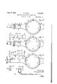
In the drawings Figure 1 is a side .elevational view of a flat plate member employed for forming the central differential casing;
Figure 2 shows the plate of Figure 1 rolled into hoop form with the abutting'ends thereof welded;
Figure 3 is a sectional view taken on line 3-3 of Figure 2;
Figure 4 shows the step of providing internal flanges'at the opposite edges of the hoop shown Figure 2; I
Figure 5'is a sectional view taken substantially 35 Figure 6 shows the central housing provided with oppositely disposed openings through which the axles of the drive mechanism are to extend;
Figure 7 is an end elevation of the housing shown in Figure 6;
Figure 8 is a plan view of a flat plate member. which maybe employed for forming the extendf ing arms of the axle housing;
Figure 9 is a sectional view of the plate of Figure 8; V
Figure 10 shows the plate rolled into tubular form and welded along its longitudinal seam;
Figure 11 is a sectional view taken on line H-ll of Figure 10;
Figure 12 shows the tube of Figure 10 with one 50 Figure 13 is an end view of. the tubeshown in Figure 12;
Figure 14 shows an optional method in which both arms may be formed from the same tube;
Figure 15 is a section taken on line |5I5 of Figure 14;
Figure 16 shows the use of a seamless tube with its end belied outwardly;
Figure 17 is an end elevation of the seamless tube shown in Figure 16; v I
Figure 18 shows the initial step for forming. reduced bearing seats on the opposite ends of the tubular arms;
Figure 19 shows the completed swaging operations on this end of the arm;
Figure 20 shows the arm of Figure 19 welded to the difierential housing end with the spring pad and brake plate attached thereto;
Figure 21 shows the completed housing;
Figure 22 shows a completed housing of the passenger car type formed in the same manner;
Figure 23 illustrates a modified manner of forming the arm;
Figure 24 is a sectional view taker. on lines 24-24 of Figures 23 and 25;
Figure 25 shows the swaging of a cylindrical arm intoan arm having a. rectangular section; and
gular arm taken on line 25-26 of Figure 25.
Referring now in detail to the drawings, the plate 5 shown in Figure 1 which may comprise a fiat strip of boiler plate or the like which is initially rolled into the circular form shown in Figure 2 and has its beveled endsfi disposed in suitable abutting engagement andwelded together as indicated at 1. v
The hoop of Figure 2 is then placed in a standard type of flanging machine and the annular edges thereof are turned inwardly as indicated at 8 to provide suitable bolting flanges for the back plate and differential carrier mounting.
The flanged circular housing of Figure-4 is then placed in any suitable type of punching machine such as a horn punch and the opposite axle openings 9 and iii are formed in the web portion of the casing. It will be noted that the openings 9 and iii are of relatively small diameter whereby suitable bearing means, or if desired, packing means or gasket means may be introduced, for preventing communication between the central housing 5 and the extending tubular arms. Such a construction is desirable in case a hydraulic differential drive is employed in place of the standard differential drive now in use.
The tubular arms for mounting the wheels are formed as shown in Figures 8 to 13, being formed from a fiat plate member l2 which is rolled into cylindrical form such as shown in Figure 19 and welded along its longitudinal seam as indicated at I3. If desired one end of the blank l2 may be scalloped as indicated at H to provide the inwardly extending arcuate portions at the end of the cylindrical tube portion in Figure 10. This facilitatesto some extent the belling of the tubular member l2 into the form shown in Figure 12, in which the end thereof is forced outwardly by means of a suitable mandrel to form the oval bell shaped section l5.
If desired afiat plate member or a seamless tubular blank of substantially twice the longitudinal extent of the blank l2 may be employed as indicated at l5 in Figure 14. Such a blank can be provided at its center with transversely extending slots Ii whereby it may be expanded or belied outwardly by engagement with the slotted portions thereof to provide the belied end sections such as shown at l8-in Figure 16. Thus the belling operation for both the tubes may be com- Flgure 26 is a sectional view through a rectanpleted in one step if tubular blanks such as the blank i5 are employed, and a double-ended expanding mandrelis employed. Obviously, however, shorter lengths of individual seamless tubing may be used and may be belied individually,
as previously described. It is optional whethera welded cylindrical blank or a seamless tubular blank is employed for forming the armsections.
In Figures 18 and 19 I disclose the method of forming suitable bearing seats at the opposite end of the blank such as the blank 20, which may be previously belied as indicated at 22 in any suitable manner. In this end forming operation a suitable punch is first inserted axially in the opposite end of the tube to force the metal internally thereof and axially rearwardly of the blank to produce a thickened internal shoulder 23.
During this'operation the end of the blank is When each of the tubes or arms has been formed in this manner suitable brake plates 28 are slipped over the ends thereof and attached to the cylindrical portion of the arm 20 adjacent the frusto-conical portion 25. The plates maybe secured to the arms by welding or the like as indicated at 29. Similarly, spring pads 30 are secured to the arms inwardly of the plates 28 by means of .welding as shown at 32. The belied ends of the arms are then trimmed in any suitable machine to it closely about the external curved surface of the central casing .5 and are aligned axially of the openings 9 and it in the housing 5 by any suitable means. The peripheral edges at the ends of the arms 20 are then welded to the central casing 5 as indicated at 33 to rigidly join the arms to the central housing.
It will be noted that .the belied portion of the arms 20 extends outwardly into substantially tangential relation with respect to the web portion of the housing 5 whereby the stresses produced tend to impose longitudinal tension and compression .stresses on the metal of the central housing whereby substantially no shearing stresses are produced along the welded joint.
After the arms have been joined to the central housing in the manner shown in Figure 20 the entire housing, including the arms, the brake plates and the spring pads, is heat-treated by heating the same up to a temperature of from 1525 to 1575 F. and then quenching the. same, after which the entire housing is reheated up to approximately 925 F. and then allowed to cool. This heat treatment removes any defects or imperfections introduced by the welding operations and makes the housing approach a substantially homogeneous mass of metal in which no parts have been weakened by the heat introduced in welding. V
The ends of the arms 20 are then machined to final form-as shown in Figure 21 to provide a bearing seat :4, an oil groove 25, and an oil retainer surface 55. At the same time the flanges 5 of the central housing 5 are tapped at spaced arms tobring them into substantial tangency 'or the like;
intervals, as indicated at 31, to receive the bolts for securing the differential carrier mechanism and back plate thereto.
If desired, the outer ends of the arms may be forged or upset to provide thickened radially extending flanges on which brake plates or the like may be mounted and the interior of the ends 20 may be suitably. machined after heat-treat ment of the housing to provide bearing seats 42. Such-forming operations are described in detail in my copending application, Serial No. 534,747, filed May 4, 1931. The housing shown in Figure 22 is especially adapted for use in passenger cars "lfidesired a tubular blank such as the blank 44 of; Figure 23, which is; initially swaged down to thicken the. same and produce some elongation thereof, may have itsendportion further swaged to. form a cylindrical end of reduced external diameter and joined to the intermediate reduced portion of the blank by the frusto-conical sec tion 46. A subsequent swaging operation may then be employed for converting the intermediate cylindrical portion of the arm 44 into .the rec-. t'angular portion ll-whereby the arm is providedwith increased strength without any corresponding increase in size as shown in Figure 26. The
I swaging operation for forming this intermediate "the formation of the intermediate rectangular rectangular section is described in detail in my copending application, Serial No. 39,666, filed September 9, 1935. This portion 41 of the arm has its vertical extent greaterthan the horizontal extent in order to provide an increased'moment-of inertia and the swaging operation also produces an increased density of metal in the corners of the section as shown at 48 which is of distinctvalue in preserving the strength of the-section. The re-, duced end of the arm 44, an indicated at 45,- may .then be upset to form radially thickened flanges, as-shown at 40 in Figure 22, or may be further reduced and thickened to form wheel bearing seats, as indicated in Figure 19. It is obvious that the arm 44 may be thus further. worked after portion, and no. illustration of such further steps is deemed necessary. The end 49. of such a a blank is then belled and trimmed in any suitable manner and joined to the central housing 5. Itis therefore believed apparent that I have provided a noveltyp of axle housing which provides for economy in formation and facilities I assembly in that the relative lengths of tube are much easier to handle during the forging operations than the tubes used in forminga one-piece butt-welding the adjacent ends of said strip,
' forming inturned flanges atopposite sides of said hoop, punching diametrically opposed axle openings in the web of said hoop, forming a pair of tubular arms, belling out one end of'each of said with the -external, surface-of' said hoop, and .welding the belled ends of said arms to the cylindrical surface-of said hoop about said openings with the axes of said-arms extending normal to the axis of revolution of said cylindrical surface to which said ends are welded.
2. The method of making a rear axle housing which comprises rolling-a flat strip into a hoop, forming inturned flanges at opposite sides of said hoop, punching diametrically opposed axle openings of a size substantially equal to the diameter of an axle spindle in the web of said hoop, forming a pair of tubular arms, belling out one end of each of said arms into an oval shape having and welding the belled ends of said arms to the cylindrical surface of said hoop about said openings.
3. The method of making a rear axle housing which comprises rolling a flat strip into a hoop, forming inturned flanges at opposite sides of said hoop, punching diametrically opposed axle '10 an axial curvature of substantially the sameradius as said hoop,-forming a thickened radial flange at the opposite ends of each of said arms,
openings of a'diameter such as to receive an axlespindle in the web of said hoop, forming a-pair of tubular arms, belling out one end of each of said arms so that the defining edges thereof are of the same curvature as said hoop, forming the intermediate portions of said arms into rec;
tangular section, forming reduced and thickened bearing portions at the opposite ends of said arms, and welding the edges of said belled ends of said arms to the cylindrical surface of said hoop about said openings with the axes of said arms extending normal to the axis of generation of the surface of saidhoop to which said edges are welded.
4. The method of making a rear axle housing which comprisesrolling a flat.strip into a hoop, forming inturned flanges at opposite sides of said hoop, punching diametrically opposed axle openings in the web of said'hoop, forming a pair of tubular arms, belling out one end of eachof said arms to bring them into substantial tangency with the external surface of said hoop, forming thickened radial upset flanges at the opposite endsof said arms, and welding the edges of the belled ends of said arms to the cylindrical surface. of said hoop about-said openings with the axes of said arms'extending normal to the axis of generation of the surface of said hoop to which said edges are welded.
5. As an article of manufacture, a rear axle housing comprising a rolled central differential casing having an uninterrupted external cylindrical surface provided with diametrically opposed openings, and a pair of tubular-arms on opposite. sides of said casing and extending normal to the axis thereof, said arms having belled ends adjacent said casing of oval concave shape fitting said external surface of said casing, and I A welded directly' thereto about'said openings.
6. An axle housing comprising a central portion forme'dgfrom a flat strip and rolled into a cylindrical casing, and a pair of hollow arms having belled end sections secured directly to. the external annular surface of said strip, each ofsaid end sections extending about and enclosing substantially one-sixth of the total circumferential surface of said casing and terminating substantially tangent to said casing. '71 In the method of forming an axle housing,
the novel steps comprising cutting arectangularq' ly shaped blank witha pair of laterally spaced arcuately shaped notches in one end thereof, rollingsaid blank into a tube and welding it longitudinally along the meeting edges, belling out said notched end to form an outwardly flared a'eheet of flat stock into a hoop, butt-welding the meeting edges, punching diametrically opposed openings in said hoop, forming inturned peripheral flanges on said hoop, and forming a pair of housing arms, each arm being formed arenas?" I 1 by cutting a rectangular am from in: stock with a pair or inwardly arched arcuate notches in one end thereof. i'orming, said blank into a tube, belling out said notched end to form an outwardly flaring oval-shaped inwardly dished portion, and welding the defining edges oi' each '01 said portions to the external annular surface at said hoop about the respective openings in said oop.
GEORGE BPA'I'IA- l0
Priority Applications (1)
| Application Number | Priority Date | Filing Date | Title |
|---|---|---|---|
| US44477A US2131237A (en) | 1935-10-11 | 1935-10-11 | Axle housing and method of making same |
Applications Claiming Priority (1)
| Application Number | Priority Date | Filing Date | Title |
|---|---|---|---|
| US44477A US2131237A (en) | 1935-10-11 | 1935-10-11 | Axle housing and method of making same |
Publications (1)
| Publication Number | Publication Date |
|---|---|
| US2131237A true US2131237A (en) | 1938-09-27 |
Family
ID=21932600
Family Applications (1)
| Application Number | Title | Priority Date | Filing Date |
|---|---|---|---|
| US44477A Expired - Lifetime US2131237A (en) | 1935-10-11 | 1935-10-11 | Axle housing and method of making same |
Country Status (1)
| Country | Link |
|---|---|
| US (1) | US2131237A (en) |
Cited By (2)
| Publication number | Priority date | Publication date | Assignee | Title |
|---|---|---|---|---|
| CN103568725A (en) * | 2012-08-08 | 2014-02-12 | 阿文美驰技术有限责任公司 | Axle housing and a method of manufacture |
| US20200009911A1 (en) * | 2018-07-06 | 2020-01-09 | Arvinmeritor Technology, Llc | Axle assembly including a wheel end and method of manufacture |
-
1935
- 1935-10-11 US US44477A patent/US2131237A/en not_active Expired - Lifetime
Cited By (4)
| Publication number | Priority date | Publication date | Assignee | Title |
|---|---|---|---|---|
| CN103568725A (en) * | 2012-08-08 | 2014-02-12 | 阿文美驰技术有限责任公司 | Axle housing and a method of manufacture |
| US20140041481A1 (en) * | 2012-08-08 | 2014-02-13 | Arvinmeritor Technology, Llc | Axle Housing and a Method of Manufacture |
| US20200009911A1 (en) * | 2018-07-06 | 2020-01-09 | Arvinmeritor Technology, Llc | Axle assembly including a wheel end and method of manufacture |
| US10946696B2 (en) * | 2018-07-06 | 2021-03-16 | Arvinmeritor Technology, Llc | Axle assembly including a wheel end and method of manufacture |
Similar Documents
| Publication | Publication Date | Title |
|---|---|---|
| US2124406A (en) | Axle housing and method of forming same | |
| US2133091A (en) | Axle and method of forming same | |
| US4220277A (en) | Axle bodies | |
| US1955824A (en) | Rear axle housing | |
| US2007793A (en) | Tubular front axle and method of making same | |
| US3535002A (en) | Tubular axle structure and method of making | |
| US3453720A (en) | Method of making axles | |
| US1978685A (en) | Method of making rear axle housings | |
| US2131237A (en) | Axle housing and method of making same | |
| US4298155A (en) | Method for making an axle spindle | |
| US2133092A (en) | Method of forming an axle housing | |
| US1945076A (en) | Method of making welded axle housings | |
| US2752673A (en) | Method of constructing a vehicle axle housing | |
| US4363522A (en) | Spindle for heavy duty truck or trailer axle | |
| US3213531A (en) | Axle housing and method of construction | |
| US4382324A (en) | Method of making a light-weight, two-wheel set | |
| HU185678B (en) | Method for producing wheel rim for tyred wheels of vehicles | |
| US2625055A (en) | Axle housing | |
| US1840941A (en) | Method of making wheel hubs | |
| US20020007556A1 (en) | Light wheel disk with large space for brake | |
| US1991199A (en) | Method of forming rear axle housings | |
| US1912594A (en) | Method of making rims | |
| US2013786A (en) | Axle | |
| US1928910A (en) | Method of forming flanged articles | |
| US2150948A (en) | Axle housing and method of making the same |