US2128357A - Recorder - Google Patents
Recorder Download PDFInfo
- Publication number
- US2128357A US2128357A US549136A US54913631A US2128357A US 2128357 A US2128357 A US 2128357A US 549136 A US549136 A US 549136A US 54913631 A US54913631 A US 54913631A US 2128357 A US2128357 A US 2128357A
- Authority
- US
- United States
- Prior art keywords
- disc
- gear
- contact
- contacts
- shaft
- Prior art date
- Legal status (The legal status is an assumption and is not a legal conclusion. Google has not performed a legal analysis and makes no representation as to the accuracy of the status listed.)
- Expired - Lifetime
Links
Images


Classifications
-
- G—PHYSICS
- G04—HOROLOGY
- G04C—ELECTROMECHANICAL CLOCKS OR WATCHES
- G04C23/00—Clocks with attached or built-in means operating any device at preselected times or after preselected time-intervals
- G04C23/14—Mechanisms continuously running to relate the operation(s) to the time of day
- G04C23/16—Mechanisms continuously running to relate the operation(s) to the time of day acting only at one preselected time or during one adjustable time interval
Definitions
- My invention relates to recording mechanisms and particularly to a timing mechanism therefor.
- An object of my invention is to provide an improved timing mechanism for a. recorder.
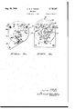
- a Figure 1 shows a cross section on a vertical median plane the timing mechanism of my invention.
- Figure 2 is a schematic wiring or circuit diagram of a recorder including the timing mechanism of my invention.
- FIG 3 is a front elevation of the timing mechanism disclosed in Figure 1.
- Figure 5 is a cross section, the plane of which is indicated by the lines 5-5 of Figure 1.
- Figure 6 is a cross section, the plane of which is indicated by the lines I-Ii of Figure 1.
- Figure 7 is a cross section, the plane of which is indicated by the lines 1-1 of Figure 1.
- Figure 8 is a cross section, theplane of which is indicated by the lines 8-8 of Figure 1.
- 'I'he recordertiming unit is adapted for use in a printing recorder having a step by step register mechanism.
- a card 356 to be printed is positioned over a mov-l able platen I9 mounted on the core 2
- are brought together, the contact 29 being mounted on a ilex- 35. ible arm 32.
- This closes an electric circuit to the solenoid 22, the circuit being traced from an .electrode 36 through a lead or wire 31 to the solenoid and thence through a conductor 38 and a Wirel 39 tothe contact 3
- the circuit then ex- 40 tends from the contact 29 and the arm 32 through v a wire 42 to an electrode 43.
- a condenser 44 is connected in parallel with lthe contacts 29 and 3
- the register mechanism In order that the register mechanism can be set, it is actuated by an arm 20
- the coil 201 is energized at $5 equal intervals to afford an impulse to the reg- Fig. 4 is a cross section, the plane of which is ister mechanism and for this purpose is included in an electric circuit.
- Connected ⁇ to the coil 201 is a wire 208 extending to a stationary contact 209 with which a movable contact 2
- the contacts 209 and 2'II are portions of a switch, generally designated 2 I2, which will later be described.
- a lead 2I3 extends to a movable contact 2I4 abutted by a stationary contact 2
- These contacts form part of a' mechanism which will be set forth in detail subsequently.
- a conductor 2I1 is joined to a stationary contact 2
- 9 is joined by a wire 22
- a conductor 223 is joined to the wire 31 and extends to a movable contact 224-while from the coil 201 a wire 22E extends to a lead 221 joined to a movable contact 228.
- the contacts 224 and 228 are part of an interrupting mechanism included in the timing unit for periodically sending impulses to the coil 201 to set the register or printing mechanism.
- the contacts 224 and 228 are mounted on pivoted arms 229 and 23
- the shaft 234 is adapted to revolve once every three minutes or iive one-hundredths of an hour. so that during this period one impulse is sent to the coil 201.
- a gear 236 which is three times the diameter of a gear 231 mounted on the shaft 238 of a synchronous motor 239.
- the synchronous motor 239 is adapted to be driven from any suitable source of regulated alternating current and causes the shaft 238 to make one revolution each minute so that the reduction between the gears 231y and 238 is proper to afford one rotation of the shaft 234 each three minutes.
- This timing unit can be replaced by any ksuitable unit which will afford the desired impulses.
- the motor 239 is provided with a neld coil 24
- ⁇ I prefer 1g that when the time of operation includes working periods and non-working periods, the register mechanism be set only during the working periods and not during the non-working periods.
- I provide a mechanism generally designated so 242. which comprises a frame mounted on a supporting bracket 241.
- the frame of the mechanism includes a front plate 242, an intermediate plate 242, an intermediate plate 22
- the coil 221 is joined 'to the wire 221 extending to the contact 222 while a wire 222 connects the coils 242 and 221 in series and the wire 222 extends to the coil 224 and to .s the lead 42 of the electrode 42.
- the other electrode 22 being connected to the wire 222 through the medium of the lead 21.
- the contact 224 is in circuit so that upon each closure of the contacts 224 and 222 the coils 224 and 221 receive l ⁇ an impulse and are energized simultaneously with the energization of the coil 291.
- the amature 222 preferably includes a pair of diametrally opposed arms 242 and 222 adapted in one position to lie against a stop pin 224 when the coils 222 and 221 are energized and to be rotated away from the stop pin 244 gq) by a spring 222 one end oi' which is mounted on a pin 221 situated on Lthe intermediate plate 22
- Each irnpulse energizing the coils 244 and 221 thereby as causes a rotational oscillation of the amature 229 against the stop pin 224 while the return movement is en'ected by the urgency of the spring 222.
- Pivoted onthe arm 222 of the amature 222 by a pin 222 is a pawl 21
- a spring 212 on the pin 269 urges the pawl 21
- the ratchet 214 is advanced one 70 tooth each three minutes or nve one-hundredths of an hour. There being fifteen teeth on the ratchet 214, the ratchet makes one complete revolution each forty-five minutes or seventy-five onehundredths of an hour.
- a detent .eter at the terminus of 212 is pivoted as at 219 on the intermediate plate 25
- a gear 222 having three equally spaced teeth 5 -defined by eight successive arcuate surfaces adapted cooperate with the periphery of the notched disc 222 and to prevent rotation of the disc 224 and the shaft 224 unless one of the arcuate notches of the disc 223 is in a position to pasa gn the projection between adjacent arcuate surfaces on the octagonal gear 222.
- Carried by the hub of the octagonal gear 229 and turning therewith in conjunction with the shaft 224 is a gear 221 having sixteen teeth and meshingwith the gg three tooth gear 222.
- the shaft 224 is advanced one step each fifteen minutes.
- the engagement of one ofthe teeth on the three tooth gear 222 entails engagement between two of the teeth on the sixteen tooth gear 221 and since the octagonal gear 222 at the same time can rotate because of the position of the notched disc 222, the shaft 224 is given one-eighth of a complete rotation for each one-third of a complete rotation of the ratchet wheel 214. thus the shaft 224 au makes a complete revolution each two hours.
- having eight equally spaced y teeth thereon.
- is in mesh with a gear wheel'292 mounted on a shaft 292 journaled in the intermediate plate 242.
- the gear 222 ia provided on its periphery with ninety-six teeth and since the eight tooth gear 29
- the shaft 222 carries a. timing member including a disc 224 removably mounted on the shaft 292 and preferably divided 'at least into twenty-four equal spaces 222 separated by radial division lines 291. Each of 5 1 -the division lines is identified by one of a series of consecutive numerals from l to 24, inclusive.
- the spaces 292 adjacent the periphery of the disc are further sub-divided into quarter m divisions 292 each of which represents fifteen minutes or .25 of an hour.
- 'I'he timing member 294 is preferably utilized to control the register; that is, to prevent the setting of the :register to indicate or cumulate 65 non-working time periods but to permit the setting or cumulation in the register of working time periods.
- the periphery of the disc 224 is made oi' irregular contour in accordance with the particular conditions-under which 70 the machine is operating. As especially shown in Figure 3, the disc is abruptly reduced in diamthe line 291 passing through the numeral 2 and representing 8:00 a. In.
- This reduced portion of the periphery is 'Il passing through the figure I2 and representing generally indicated by the reference numeral 290 and extends to the terminus of the radial line 291 12:00 noon.
- the ⁇ reduced portion 203 is z of akperipheral extent representingthe working time period between 8:00 a. m. and 12:00 noon.
- the periphery of thedisc 294 is then uninterrupted between the termini of the radial lines 291 passing through the numerals
- of the disc A294 is uninterrupted for the non-workingy time period between 12:00 oclock noon and 1:00 oclock p. rn. or 12:00 and 13:00'i:i'cltxe,k,v
- the periphery of the rdisc 294 between the terminus of the portion 302 and extending from the radial line between the numerals I0 and I1 representing 16:00 and 17:00 oclock around the periphery of the disc to the. terminus of the lradial line 0 representing 8:00 oclock is uninterrupted and is proportional to the non-working period between half past four oclock p. m. or half past sixteen o'clock or 16:50 oclock and eight oclock a. in. or 8:00 oclock.
- the disc 294 makes one complete rotation and the successive portions 299, 30
- the irregular periphery of the timing member 294 can be arranged as desired by removing p0rtions of the disc to give any relationship desired between working time periods and non-working time periods.
- the disc is uninterrupted on its periphery and is cut or interrupted to suit the particular conditions under which the machine is to be operated. If desired, the disc can be oi' relatively thin metal marked, perforated or scored so that the periphery can easily be mutilated.
- the irregularity in the periphery of the disc 294 is utilized to prevent impulses from affecting the setting of the register.
- Mounted on the front plate 248 is an insulating block 303 on which a lever 304 is pivoted by a pin 309.
- One end of the lever is provided with a, follower 301 adapted to contact the'periphery of the disc 294 so that the irregularities thereof oscillate the lever about its pivotal point.
- the A1ever'304 at its other extremity carries the movable Contact 2I9 which cooperates with the stationary contact 2
- 9 and 2I8 are vseparated thereby breaking the circuit from the timing unit to the coil 201 so that any vimpulses originating in the timing unit are not effective on the coil 201 and the register is not set.
- 3 are gravitally closed so that impulses originating in the timing unit are imparted to the coil 201 and serve to set the register.
- the timing unit operates during a predetermined interval of time but the pass a given 24:00 oclock or'12r00 oclock noon.
- 'Ihese contacts are mounted en resilient arms 3I4 and 3
- 2 is connected by a wire 3
- is completed by a wire 322 extending from the coil to the lead .31.
- the electromagnet When the pin 3I
- the mechanism as so far described controls the impulses from the continuously operating timing unit in such a fashion that the register is actuated to accumulate only working time periods of the total elapsed or predetermined interval of time on a daily basis.
- I provide means for causing the mechanism of the register to accumulate working time periods for time intervalslonger than one day and preferably of the order of one week.
- a gear 326 having eighty-four teeth around its periphery.
- Meshing withthe gear 324 isk an idler gear 321 mounted freely on a pin 329 ydisposed on the front plate 243.
- Adapted to mesh with the gear 321 is a single tooth gear 329 forming an extension of the shaft 234 and conveniently fabricated by cutting away all but one of the teeth of the gear 29
- the gear 326 is provided with a plurality of bosses 334 to which a week timing member 333 is fastened by screws 331. rIhe face of the week timing member is Adivided into seven spaces 338 separated by radial lines 339 and is preferably afforded indicia, such as 34
- a lever 343 mounted on a pivot pin 344 extending from the insulating block 303 and at one end carrying a follower 346.
- the other end of the lever 343 carries the Contact 2I4 while the cooperating contact 2I6 is mounted on the insulating block 303.
- the projection 342 contacts the follower 346 and separates the contacts 2
- the mechanism can be arranged so that non-working time during a month or during a year can be prevented Irorn being set in the register by suitably opening the circuit through the coil 201.
- a manual switch 2I2 controlling the contacts 209 and 2li. Normally, these contacts ⁇ are closed but in the event of a holiday, they are manually separated, thereby interrupting the circuit to the coil 201 and preventing the setting in the register of non-working time periods during the holiday.
- a timing device for use in an electric circuit including a plate, a day disc rotatably mounted on said plate and having an irregular periphery, a week disc rotatably mounted on said plate coaxially with said day disc and having an irregular periphery, a first pair oi.' contacts and a second pair of contacts in series in said circuit, a first lever for actuating said first pair of contacts pivoted with respect to said plate and bearing at one extremity on the periphery of said day disc, a second lever for actuating said second pair of contacts pivoted with respect to said plate and bearing at one extremity on the periphery of said week disc, a drive shaft on said plate adapted to rotate, means including an intermittent action timing mechanism for rotating said drive shaft intermittently, andmeans connecting said day disc directly to said drive shaft and said week disc directly to said drive shaft for rotation thereby at diflerent rates.
Description
Aug. 3o, 193s.
C. M. F. FRIDEN RECORDER Fil'ed July 7, 1931 3 Sheets-Sheet l INVEN TOR. C or/ M. E Fr/dz/l A TTOR Aug. 30, 1938. c. M. F. FRIDEN 2,128,357
RECORDER Filed July '7, 1931 3' Sheets-Sheet 2 F11-51.43.... FIE' QL A TTOR \12- 30, 1938- c. M. F.1'FR1DEN 2,128,357
RECORDER Film1l July 7, 1931Y s sheets-sheet s A TTORNEYS.V
Patented Aug. 30, 1938 UNITED STATES PATENT OFFICE RECORDER Application July 1, 1931, Serial No. 549,136
1 Claim.
My invention relates to recording mechanisms and particularly to a timing mechanism therefor.
An object of my invention is to provide an improved timing mechanism for a. recorder.
The foregoing and other objects are attained in the embodiment of the invention shown in theV drawings, in which AFigure 1 shows a cross section on a vertical median plane the timing mechanism of my invention.
Figure 2 is a schematic wiring or circuit diagram of a recorder including the timing mechanism of my invention.
Figure 3 is a front elevation of the timing mechanism disclosed in Figure 1.
indicated by the lines 4-4 of Figure 1.
Figure 5 is a cross section, the plane of which is indicated by the lines 5-5 of Figure 1.
Figure 6 is a cross section, the plane of which is indicated by the lines I-Ii of Figure 1.
Figure 7 is a cross section, the plane of which is indicated by the lines 1-1 of Figure 1.
Figure 8 is a cross section, theplane of which is indicated by the lines 8-8 of Figure 1.
'I'he recordertiming unit is adapted for use in a printing recorder having a step by step register mechanism. In this type of mechanism, a card 356 to be printed is positioned over a mov-l able platen I9 mounted on the core 2| of a solenoid 22. When the card is moved against an abutment 24, contacts 29 and 3| are brought together, the contact 29 being mounted on a ilex- 35. ible arm 32. This closes an electric circuit to the solenoid 22, the circuit being traced from an .electrode 36 through a lead or wire 31 to the solenoid and thence through a conductor 38 and a Wirel 39 tothe contact 3|. The circuit then ex- 40 tends from the contact 29 and the arm 32 through v a wire 42 to an electrode 43. A condenser 44 is connected in parallel with lthe contacts 29 and 3| by wires 46 and 41.
When the platen I9 rises due to the energize.- 45 tion of the solenoid 22, an imprint is made on the card 356 by the register (not shown) and the card is liftedfoii the abutment 24 so that the resilient arm 32 opens the contacts 29 and 3| and the parts are restored to their initial inoperative positions.
In order that the register mechanism can be set, it is actuated by an arm 20| secured to an amature 202 responsive to energization of an electromagnet 201. The coil 201 is energized at $5 equal intervals to afford an impulse to the reg- Fig. 4 is a cross section, the plane of which is ister mechanism and for this purpose is included in an electric circuit. Connected `to the coil 201 is a wire 208 extending to a stationary contact 209 with which a movable contact 2| I is normally in abutment. The contacts 209 and 2'II are portions of a switch, generally designated 2 I2, which will later be described.
From the contact 2II a lead 2I3 extends to a movable contact 2I4 abutted by a stationary contact 2|6. These contacts form part of a' mechanism which will be set forth in detail subsequently. From thestationary contact 2I6 a conductor 2I1 is joined to a stationary contact 2|8 abutted by a movable contact 2 I9 which form part of a mechanism later to be described; The Contact 2|9 is joined by a wire 22| to a lead 222 extending to the wire 42 and thence to the electrode 43. From the other electrode 36 a conductor 223 is joined to the wire 31 and extends to a movable contact 224-while from the coil 201 a wire 22E extends to a lead 221 joined to a movable contact 228. v
The contacts 224 and 228 are part of an interrupting mechanism included in the timing unit for periodically sending impulses to the coil 201 to set the register or printing mechanism. The contacts 224 and 228 are mounted on pivoted arms 229 and 23|, respectively, each 0f which rides on one of two similar cams 232 and 233 mounted on a shaft 234. 'Ihe cams are slightly out of phase on the shaft 234 so that as they revolve the arm 23| first drops from thecam 233 permitting the contact 228 to abut the contact 224 and shortly thereafter the arm 229 drops from the cam 232 causing the contact 224 to separate from the contact 228 thereby again opening the circuit after a momentary closure thereof. The shaft 234 is adapted to revolve once every three minutes or iive one-hundredths of an hour. so that during this period one impulse is sent to the coil 201.
For rotating the 4shaft 234 I preferably mount on it a gear 236 which is three times the diameter of a gear 231 mounted on the shaft 238 of a synchronous motor 239. As ordinarily supplied to the trade, the synchronous motor 239 is adapted to be driven from any suitable source of regulated alternating current and causes the shaft 238 to make one revolution each minute so that the reduction between the gears 231y and 238 is proper to afford one rotation of the shaft 234 each three minutes. This timing unit can be replaced by any ksuitable unit which will afford the desired impulses.
In the present instance, the motor 239 is provided with a neld coil 24| joined by a wire 242 to the lead 222 extending to the electrode 22 and by a wire 242 extending to the lead 42 joined to the electrode 42 so that the timing unit opg erates continuously and periodically causes impulses in the circuit of the coil 221l preferably, one
impulse each three minutes or nve one-hundredths of an hour. According to this mechanlsm. therefore. during the continued operation 1o ofthetlmingunit theregisterissetat periods of three minutes or ilve-one-hundredths of an hour.
`Although the described mechanism alone is mutable for use in some environments,` I prefer 1g that when the time of operation includes working periods and non-working periods, the register mechanism be set only during the working periods and not during the non-working periods. To this end I provide a mechanism generally designated so 242. which comprises a frame mounted on a supporting bracket 241. The frame of the mechanism includes a front plate 242, an intermediate plate 242, an intermediate plate 22|. and a rear plate 222, from which the bracket 241 extends, All u of the plates are suitably joined by through bolts .222 and are spaced by sleeves 244 surrounding the through bolts and interposed between the respec- .tive plates. i
Mounted between the intermediate 242 te, and 22| isa pair of electromagnetic colla 224 and 221. respectively: The coil 221 is joined 'to the wire 221 extending to the contact 222 while a wire 222 connects the coils 242 and 221 in series and the wire 222 extends to the coil 224 and to .s the lead 42 of the electrode 42. The other electrode 22 being connected to the wire 222 through the medium of the lead 21. the contact 224 is in circuit so that upon each closure of the contacts 224 and 222 the coils 224 and 221 receive l` an impulse and are energized simultaneously with the energization of the coil 291.
Energization of the coils 224 and 221 attracts an armature 222 which is mounted for rotationl on a shaft 22| journaled between the intermediate lV plates 242 and 22|. The amature 222 preferably includes a pair of diametrally opposed arms 242 and 222 adapted in one position to lie against a stop pin 224 when the coils 222 and 221 are energized and to be rotated away from the stop pin 244 gq) by a spring 222 one end oi' which is mounted on a pin 221 situated on Lthe intermediate plate 22| and the other end of which is connected to a pin 222 on the arm 222 of the armature 242. Each irnpulse energizing the coils 244 and 221 thereby as causes a rotational oscillation of the amature 229 against the stop pin 224 while the return movement is en'ected by the urgency of the spring 222.
Pivoted onthe arm 222 of the amature 222 by a pin 222 is a pawl 21| operating in an aperture 212 in the intermediate plate 23|. A spring 212 on the pin 269 urges the pawl 21| into engagement with a ratchet 214 havingni'teen teeth and mounted to rotate in conjunction with a bushing 212 encompassing a plug 211 fixed in the intergg mediate plate 22| and forming a journal for the shaft 24|.
lnce the coils 222 and 221 are energized once each five one-hundredths of an hour or each three minutes, the ratchet 214 is advanced one 70 tooth each three minutes or nve one-hundredths of an hour. There being fifteen teeth on the ratchet 214, the ratchet makes one complete revolution each forty-five minutes or seventy-five onehundredths of an hour. In order to prevent a 1s, retrograde movement of the ratchet 214, a detent .eter at the terminus of 212 is pivoted as at 219 on the intermediate plate 25| and is urged by a spring 22| into engagement with the ratchet 214. Mounted to rotate in unison with therratchet 214 by being fixed to the bushing 212 is a gear 222 having three equally spaced teeth 5 -defined by eight successive arcuate surfaces adapted cooperate with the periphery of the notched disc 222 and to prevent rotation of the disc 224 and the shaft 224 unless one of the arcuate notches of the disc 223 is in a position to pasa gn the projection between adjacent arcuate surfaces on the octagonal gear 222. Carried by the hub of the octagonal gear 229 and turning therewith in conjunction with the shaft 224 is a gear 221 having sixteen teeth and meshingwith the gg three tooth gear 222.
Since the three tooth gear 222 makes one complete revolution in unison with the ratchet wheel 214 in forty-flve minutes, one of the teeth of the three tooth gear 222 meshes with the gear 221 w each fifteen minutes so that the shaft 224 is advanced one step each fifteen minutes. The engagement of one ofthe teeth on the three tooth gear 222 entails engagement between two of the teeth on the sixteen tooth gear 221 and since the octagonal gear 222 at the same time can rotate because of the position of the notched disc 222, the shaft 224 is given one-eighth of a complete rotation for each one-third of a complete rotation of the ratchet wheel 214. thus the shaft 224 au makes a complete revolution each two hours.
'Ihe other extremity of the shaft 224 is formed to provide a gear 29| having eight equally spaced y teeth thereon. This gear 29| is in mesh with a gear wheel'292 mounted on a shaft 292 journaled in the intermediate plate 242. The gear 222 ia provided on its periphery with ninety-six teeth and since the eight tooth gear 29| makes a complete revolution once in each two hours, the gear 292 and the shaft 292 make a complete revolution no.
once each twenty-four hours. The shaft 222 carries a. timing member including a disc 224 removably mounted on the shaft 292 and preferably divided 'at least into twenty-four equal spaces 222 separated by radial division lines 291. Each of 5 1 -the division lines is identified by one of a series of consecutive numerals from l to 24, inclusive.
.indicating the twenty-fourhours of a day.
Preferably, the spaces 292 adjacent the periphery of the disc are further sub-divided into quarter m divisions 292 each of which represents fifteen minutes or .25 of an hour.
'I'he timing member 294 is preferably utilized to control the register; that is, to prevent the setting of the :register to indicate or cumulate 65 non-working time periods but to permit the setting or cumulation in the register of working time periods. For this purpose the periphery of the disc 224 is made oi' irregular contour in accordance with the particular conditions-under which 70 the machine is operating. As especially shown in Figure 3, the disc is abruptly reduced in diamthe line 291 passing through the numeral 2 and representing 8:00 a. In.
This reduced portion of the periphery is 'Il passing through the figure I2 and representing generally indicated by the reference numeral 290 and extends to the terminus of the radial line 291 12:00 noon. Thus, the` reduced portion 203 is z of akperipheral extent representingthe working time period between 8:00 a. m. and 12:00 noon.
The periphery of thedisc 294 is then uninterrupted between the termini of the radial lines 291 passing through the numerals |2 and I3 repre-v senting 12:00 oclock noon and 1:00 oclock p. m. or 13 oclock. Thus, the peripheral portion generally designated by the numeral 30| of the disc A294 is uninterrupted for the non-workingy time period between 12:00 oclock noon and 1:00 oclock p. rn. or 12:00 and 13:00'i:i'cltxe,k,v
. Again the periphery of thezdisc 294fis5f`interrupted, as generally indicated @by the.` "numeral 302, from the terminus of theradialLline/291 passing through the numeral I3'I with the inter- -ruption extending to a radial line betweenathe lines associated with the` numerals yI0 and I1. The latter radial line represents half past four oclock p. m. or half past sixteen oclock or 16:50 oclock. Thus, the working period between 13:00 and 16:50 oclock is represented by an interrupted portion 302 of proportional extent. The periphery of the rdisc 294 between the terminus of the portion 302 and extending from the radial line between the numerals I0 and I1 representing 16:00 and 17:00 oclock around the periphery of the disc to the. terminus of the lradial line 0 representing 8:00 oclock is uninterrupted and is proportional to the non-working period between half past four oclock p. m. or half past sixteen o'clock or 16:50 oclock and eight oclock a. in. or 8:00 oclock. During each twenty-four hours the disc 294 makes one complete rotation and the successive portions 299, 30| and 302 point once. A
The irregular periphery of the timing member 294 can be arranged as desired by removing p0rtions of the disc to give any relationship desired between working time periods and non-working time periods. Originally the disc is uninterrupted on its periphery and is cut or interrupted to suit the particular conditions under which the machine is to be operated. If desired, the disc can be oi' relatively thin metal marked, perforated or scored so that the periphery can easily be mutilated.
The irregularity in the periphery of the disc 294 is utilized to prevent impulses from affecting the setting of the register. Mounted on the front plate 248 is an insulating block 303 on which a lever 304 is pivoted by a pin 309. One end of the lever is provided with a, follower 301 adapted to contact the'periphery of the disc 294 so that the irregularities thereof oscillate the lever about its pivotal point. The A1ever'304 at its other extremity carries the movable Contact 2I9 which cooperates with the stationary contact 2|3 likewisemounted on the insulatingblock 303.I During the time that the uninterrupted portion of the disc ist is in Contact with the follower sur, the contacts 2|9 and 2I8 are vseparated thereby breaking the circuit from the timing unit to the coil 201 so that any vimpulses originating in the timing unit are not effective on the coil 201 and the register is not set. However, when the interrupted portion of the disc 294 is adjacent the follower 301 the contacts 2|9 and 2|3 are gravitally closed so that impulses originating in the timing unit are imparted to the coil 201 and serve to set the register. Thus, the timing unit operates during a predetermined interval of time but the pass a given 24:00 oclock or'12r00 oclock noon. 'Ihese contacts are mounted en resilient arms 3I4 and 3|0 respectively which are fastened to an insulating block 3|1 projecting from the front plate 243. The contact 3|2 is connected by a wire 3|3 to the conductor 222 while the contact 3|3 is connected by a wire 3|9 to an electromagnetic coil 32|. The circuit to the electromagnetic coil 32| is completed by a wire 322 extending from the coil to the lead .31.
When the pin 3I| on the disc 294 causes the contacts 3|2 and 3| 3 to abut, the electromagnet isenergized, thus setting the day wheel of the register. At exactly midnight. or 24:00` oclock when the pin 3|| rides over the arm 3I4 of the contact 3|2 and releases the contact, the resiliency of the mounting arm causes the contacts to spring apart, thus breaking the circuit and de# energizing the electromagnet 32|.
The mechanism as so far described controls the impulses from the continuously operating timing unit in such a fashion that the register is actuated to accumulate only working time periods of the total elapsed or predetermined interval of time on a daily basis.
In accordance with my invention I provide means for causing the mechanism of the register to accumulate working time periods for time intervalslonger than one day and preferably of the order of one week. For this purposev there is mounted rotatably on the shaft 293 a gear 326 having eighty-four teeth around its periphery. Meshing withthe gear 324 isk an idler gear 321 mounted freely on a pin 329 ydisposed on the front plate 243. Adapted to mesh with the gear 321 is a single tooth gear 329 forming an extension of the shaft 234 and conveniently fabricated by cutting away all but one of the teeth of the gear 29|. Since the shaft 284 rotates a complete revolution for each two hours and since the distance oi.' one tooth forcing the bell crank 32| to ride over one tooth and again engage the idler gear 321.
As particularly shown in Figure 4 the gear 326 is provided with a plurality of bosses 334 to which a week timing member 333 is fastened by screws 331. rIhe face of the week timing member is Adivided into seven spaces 338 separated by radial lines 339 and is preferably afforded indicia, such as 34|, giving the names of the days of the week. Although a major part oi the periphery of the member 336 is regular in contour, a portion 342 thereof representing a time period from 2:00 oclock p. m. Sunday until/.4:30 o'clock p. m. Sunday provides a projection. In the path of the projection 342 is a lever 343 mounted on a pivot pin 344 extending from the insulating block 303 and at one end carrying a follower 346. The other end of the lever 343 carries the Contact 2I4 while the cooperating contact 2I6 is mounted on the insulating block 303. During substantially all o! the rotation of the member 336, that is, during all of the days of the week except Sunday, the follower 346 is out of contact with the periphery of the member 336 and the contacts 2|4 and 2l6 are in abutment thereby permitting the circuit to the coil 201 to be completed momentarily and under the additional control of the contacts 2I8 and 2|9. However, on Sunday between the hours of 2:00 p. m. and 4:30 p. m., for example, the projection 342 contacts the follower 346 and separates the contacts 2|4 and 2I6 thus breaking the circuit to the coil 201 and preventing any impulses originating in the timing mechanism during this non-working time period from being communicated to and set in the register.
By providing other timing members similar to the member 294 and the member 330, the mechanism can be arranged so that non-working time during a month or during a year can be prevented Irorn being set in the register by suitably opening the circuit through the coil 201. As I -have indicated in Figure 2, there is in the present instance provided a manual switch 2I2 controlling the contacts 209 and 2li. Normally, these contacts `are closed but in the event of a holiday, they are manually separated, thereby interrupting the circuit to the coil 201 and preventing the setting in the register of non-working time periods during the holiday.
It is to be understood that I do not limit myself to the form of the recorder shown and described herein, as the invention, as set forth in the following claim may be embodied in a plu rality of forms.
I claim:
A timing device for use in an electric circuit including a plate, a day disc rotatably mounted on said plate and having an irregular periphery, a week disc rotatably mounted on said plate coaxially with said day disc and having an irregular periphery, a first pair oi.' contacts and a second pair of contacts in series in said circuit, a first lever for actuating said first pair of contacts pivoted with respect to said plate and bearing at one extremity on the periphery of said day disc, a second lever for actuating said second pair of contacts pivoted with respect to said plate and bearing at one extremity on the periphery of said week disc, a drive shaft on said plate adapted to rotate, means including an intermittent action timing mechanism for rotating said drive shaft intermittently, andmeans connecting said day disc directly to said drive shaft and said week disc directly to said drive shaft for rotation thereby at diflerent rates.
CARL M. F. FRIDEN.
Priority Applications (1)
| Application Number | Priority Date | Filing Date | Title |
|---|---|---|---|
| US549136A US2128357A (en) | 1931-07-07 | 1931-07-07 | Recorder |
Applications Claiming Priority (1)
| Application Number | Priority Date | Filing Date | Title |
|---|---|---|---|
| US549136A US2128357A (en) | 1931-07-07 | 1931-07-07 | Recorder |
Publications (1)
| Publication Number | Publication Date |
|---|---|
| US2128357A true US2128357A (en) | 1938-08-30 |
Family
ID=24191815
Family Applications (1)
| Application Number | Title | Priority Date | Filing Date |
|---|---|---|---|
| US549136A Expired - Lifetime US2128357A (en) | 1931-07-07 | 1931-07-07 | Recorder |
Country Status (1)
| Country | Link |
|---|---|
| US (1) | US2128357A (en) |
Cited By (1)
| Publication number | Priority date | Publication date | Assignee | Title |
|---|---|---|---|---|
| US2487573A (en) * | 1945-06-26 | 1949-11-08 | Landis & Gyr Ag | Switch contact |
-
1931
- 1931-07-07 US US549136A patent/US2128357A/en not_active Expired - Lifetime
Cited By (1)
| Publication number | Priority date | Publication date | Assignee | Title |
|---|---|---|---|---|
| US2487573A (en) * | 1945-06-26 | 1949-11-08 | Landis & Gyr Ag | Switch contact |
Similar Documents
| Publication | Publication Date | Title |
|---|---|---|
| US2128357A (en) | Recorder | |
| US3353347A (en) | Reminder clock | |
| US2072457A (en) | Time indicating device | |
| US2283993A (en) | Production indicating apparatus | |
| US2301942A (en) | Timing mechanism | |
| US4014163A (en) | Clockwork for designating time and tide | |
| US2580787A (en) | Impulse-actuated program device | |
| US1791927A (en) | Program device | |
| US3603073A (en) | Electric timepiece | |
| US1322216A (en) | Chime-clock. | |
| US2080330A (en) | Electric program clock | |
| US2658329A (en) | Electrically wound and set watch | |
| US1432627A (en) | shenstone | |
| US2927418A (en) | Calendar clock | |
| US2736023A (en) | La vergne h | |
| US2369917A (en) | roitman | |
| US3834151A (en) | Timepiece with automatic calendar | |
| US2246883A (en) | Date indicator for timepieces | |
| US2039920A (en) | Signaling apparatus | |
| US1810732A (en) | Program machine | |
| US1863926A (en) | Perpetual calendar | |
| US2405841A (en) | Program instrument | |
| US3288934A (en) | Time totalizer system for telephone circuits and the like | |
| US3209997A (en) | Taximeters | |
| US2657748A (en) | Device for producing signals at predetermined intervals |