US2125834A - Apparatus for inserting pintles in box parts - Google Patents
Apparatus for inserting pintles in box parts Download PDFInfo
- Publication number
- US2125834A US2125834A US26261A US2626135A US2125834A US 2125834 A US2125834 A US 2125834A US 26261 A US26261 A US 26261A US 2626135 A US2626135 A US 2626135A US 2125834 A US2125834 A US 2125834A
- Authority
- US
- United States
- Prior art keywords
- wire
- pintles
- plate
- pawl
- die
- Prior art date
- Legal status (The legal status is an assumption and is not a legal conclusion. Google has not performed a legal analysis and makes no representation as to the accuracy of the status listed.)
- Expired - Lifetime
Links
Images


Classifications
-
- B—PERFORMING OPERATIONS; TRANSPORTING
- B21—MECHANICAL METAL-WORKING WITHOUT ESSENTIALLY REMOVING MATERIAL; PUNCHING METAL
- B21D—WORKING OR PROCESSING OF SHEET METAL OR METAL TUBES, RODS OR PROFILES WITHOUT ESSENTIALLY REMOVING MATERIAL; PUNCHING METAL
- B21D51/00—Making hollow objects
- B21D51/16—Making hollow objects characterised by the use of the objects
- B21D51/52—Making hollow objects characterised by the use of the objects boxes, cigarette cases, or the like
-
- Y—GENERAL TAGGING OF NEW TECHNOLOGICAL DEVELOPMENTS; GENERAL TAGGING OF CROSS-SECTIONAL TECHNOLOGIES SPANNING OVER SEVERAL SECTIONS OF THE IPC; TECHNICAL SUBJECTS COVERED BY FORMER USPC CROSS-REFERENCE ART COLLECTIONS [XRACs] AND DIGESTS
- Y10—TECHNICAL SUBJECTS COVERED BY FORMER USPC
- Y10T—TECHNICAL SUBJECTS COVERED BY FORMER US CLASSIFICATION
- Y10T29/00—Metal working
- Y10T29/24—Hinge making or assembling
Landscapes
- Engineering & Computer Science (AREA)
- Mechanical Engineering (AREA)
- Wire Processing (AREA)
Description
Aug, 2, 1938. H. HERMAN! 2,125,834
APPARATUS FOR INSERTING PINTLES IN BOX PARTS Filed June 12, 1935 4 Sheets-Sheet 1 v H l' Aug 2, 1%& IH. HERMAN! 2,125,834
APPARATUS FOR INSEHTING PINTLES IN BOX PARTS Filed Jurie 12, 1935 4 Shee'ts-Shee t 2 INVENTOR.
'Hermam 2, 198.. I H. HERMAN! 2,125,334
APPARATUS FOR INSERTING PINTLES IN BOX PARTS Filed June 12, 1935 4 Sheets-Sheet 3' 85' LNVENTOR. Hang Hermam '76 BY 04,42 B M as ATTORNEY.
m1 2, 1938. H. HERMAN] APPARATUS FOR INSERTING PINTLES IN BOX PARTS Filed June 12, 1935 4 Sheets-Sheet 4 INVENTOR.
' Hengy Her-mam Patented Aug. 2, 1938 APPARATUS FOR INSERTING PINTLES IN BOX PARTS Henry Hermani, Baltimore, Md., assignor, by
mesne assignments,
to Owens-Illinois Can Company, Wilmington, Del., a corporation of Delaware Application June 12, 1935, Serial No. 26,261
6 Claims.
particularly to improvements in the structure disclosed in my prior Patent No. 1,267,409.
In my said prior patent I have disclosed an apparatus to form the blanks to receive the pintles, and means to form the pintles and insert them in the blanks. In said patent the blanks are introduced into the general feeding mechanism by a traveling conveyor on which the blanks are placed with their open sides disposed in the same direction, the conveyor moving the blanks successively into contact with means acting somewhat on the order of an escapement to permit the blanks to move forward individually at proper timed intervals. Each escaping blank is introduced into a carrier channel within which it is advanced to position the blank .at predetermined points in the channel. At predetermined intervals the channel also shifts laterally to position the blanks successively in operative relation to the several forming stations or mechanisms, indicated generally in the said patents as A, B, C and D, (see Figs. 4-7). In the said patent station A is the entrance to the said channel, station C is the station at which the blank is prepared for pintle application, and station D is the pintle applying station; no work being performed at station B, whichis designed to provide the supply for station C without complicating the general operation by attempting to introduce a blank and properly located on the die at station 0.
The present invention relates particularly to pintle forming and applying mechanisms to be 35 located at station D, and the operations leading up thereto may be carried out by the same mechanism as shown and described in the said patent in connection with stations A, B and C.
Generally stated the present invention resides in the provision of means for feeding a wire strand step by step to improved means for cutting and applying the pintles to the box parts, and characterized by relatively simple construction and arrangement of parts, positive operation, and of such nature as not to become easily damaged or placed out of commission during operation of the apparatus, thus affording a greater output and requiring less repairs and attention.
As in my said patent, the present invention utilizes a ram or reciprocating punch plate operating transversely to the carrier channel for the box parts, and eifecting through its reciprocating movements the operation of the wire feeding means, as well as the means for forming and inserting the pintles.
. The present invention also includes the provision of relatively simple means, operable by the movements of the successive can parts onto the die which receives the same for application of the pintles, to effect control of the wire feeding means so that wire is fed to the cutting and applying mechanism each time a can part is placed on said die, but in the event a can part is not fed to the die, to make the wire feeding mechanism inoperative.
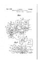
The foregoing and other objects and advantages of the invention and the improvements provided thereby will become more apparent and will be pointed out during the course of the following detailed description of the accompanying drawings, in which Fig. 1 is a front elevation of the end of the apparatus or machine carrying the wire feeding mechanism and the operating means therefor;
Fig. 2 is a front elevation of a portion of the machine showing guiding means for the wire, and the cutting means co-operating therewith to form the pintles, and fragments of the blank and die holding the blank, in section;
Fig. 3 is an enlarged sectional view taken on the line 33 of Fig. 1;
Fig. 4 is an enlarged sectional view taken on the line 4-4 of Fig. 6;
Fig. 5 is an enlarged sectional view taken on the line 55 of Fig. 2;
Fig. 6 is an enlarged rear elevation of the end of the machine shown in Fig. 1 showing the operating means for the wire feeding mechanism, and controlling mechanism therefor;
Figs. '7, 8 and 9 are detail views partly in ele-' vation and partly in section illustrating the means for inserting and cutting the pintles and the position of the parts during the several steps leading up to the time when the pintle is finally inserted;
Fig. 10 is a top plan view of the die which receives the can or box part for application of the pintle thereto, together with the pintle inserting means, and the means controlling preventing feeding of the wire if no blank is supplied to the die;
Fig. 11 is a sectional view taken on the line H-ll of Fig. 12;
Fig. 12 is a front elevation of the die and mechanism for inserting the pintles;
Fig. 13 is an end elevation of the mechanism shown in Fig. 12; and
Fig. 14 is a perspective view of the part or plunger which engages and moves the pintles into final inserted position on the blanks.
In Fig. 1 of the drawings the numeral |4 designates the plate or bracket at one end of the machine (which corresponds to the plate or bracket 39!) of Patent 1,267,409) and which may be secured in place or on the frame of the machine by any suitable means such as explained in the said patent. The numeral |5 designates bolts which secure one of a pair of guides Hi to bracket l4, said guides being the same in construction and purpose as the guides of the said patent, and between which operate the head (corresponding to the part 65 of the said patent) and connected by the coupling l8 to a crank mechanism such as that shown in Fig. 1 of the said patent and operated by shaft 3| in said patent, but not shown in this application. The punch plate I9 is secured to head I! by bolts 20 for reciprocating movement therewith.
Up to the present point the construction disclosed is substantially the same as that of the corresponding parts of the said patent. However, whereas in the patent the wire feeding mechanism is operated by crank and levers driven from the shaft 3| of the patent, under the present invention I provide for the elimination of a great many of these parts by the provision of a simply and strongly constructed cam and lever mechanism operated directly by the reciprocating movement of the head H. To this end I provide part 2|, secured to the plate |9 by bolts 22 and having a portion extending up along and adjacent said one of the brackets I6. Cam plate 23 is adjustably connected to the upward extension of part 2| by bolt and slot arrangements 24 to provide for adjustability of the cam plate which, of course, reciprocates with the head I! and plate l9 due to the connections mentioned.
The outer end of the plate 23 is provided with a cam slot 25 in which is disposed a roller 26 mounted on a lug 21 on a lever 28 pivoted at its upper end on a stud 29 supported by the bracket l4. The lower end of the lever 28 is pivotally connected at 30 to one end of a link 3|, the other end of which is connected to a plate 32 (see also Figs. 4 and 6). The plate 32 is journaled on a shaft 33, one end of which is secured to bracket H by washer and nut 34. The plate 32 is held on the other end of shaft 33 by a similar washer and bolt 35, and has free oscillating movement on the shaft. A pawl 36 is pivotally connected to the plate 32 at 31 for engagement with the teeth of a ratchet 3B journaled on a sleeve 39 pinned to the shaft 33 as indicated at 4|].
The ratchet 38 is connected by screws 4| to a relatively large gear 42 journaled on a sleeve 43 on shaft 33.
Considering the structure thus for defined it should be obvious that reciprocation of the plate 23 with the parts |9 and 2| will move the roller 26 in the cam slot 25 oscillating lever 28 on pivot 29, which, through the link 3| connected to the lower end of the lever 28 and to part 32, moves the pawl to engage the ratchet 38 and partially rotate the ratchet subject to the conditions hereinafter given in connection with the rendering of the wire feeding mechanism inoperative.
In Figs. 1, 2 and 3 I have shown the means for feeding a wire W predetermined distances so that predetermined lengths of the wire may be cut to form the pintles. Brackets 45 have upper flanges 46 secured to the plate M as by means of bolts 41, and support bearings 48 through which are journaled shafts 49. At one side of each of the brackets 45, and at corresponding ends of the shafts 49, are pairs of gears 50 the lower of which mesh with the gear 42 to be driven thereby. The upper of the gears 50 mesh with the lower ones and are driven thereby. The rotation of said gears is obviously such as to cause similar movement of the gears on the respective brackets 45 to cause advancing movement of the wire W which is frictionally gripped between grooves 52 in driven rollers 53 keyed to shafts 49 as indicated at 54. Of course the gears 50 are also keyed to the shafts 49 as indicated at 55, so that when gear 42 is rotated as hereinafter pointed out all of the gears 50 and the wire feed or driven rollers 53 will rotate to advance the wire step by step. Adjusting screws 56 may be provided to regulate pressure between the rollers 53 in known manner, such means being also shown in my said prior patent.
The parts of the Wire feeding mechanism, that is, the arrangement of gears and feeding rollers above described is substantially the same as in the said prior patent, but the means for guiding the wire from the feed or driven rollers 53 is different in the present case, and is shown best in Figs. 2 and 5. The present guide means is arranged to guide the wire to the pintle forming mechanism and into the box parts at one end thereof at an exact angle and under exact tension. In Figs. 2-5 the numerals 60 and BI designate respectively the lower and upper plates of the wire guiding mechanism each having V- shaped channels cut in their confronting faces and alined with each other, as well as with the grooves 52, to form a channel 61 between plates 69 and 6|. The plates 60 and 6| are arranged between flanges 62 and 63 of a bracket or support 64 secured to the bracket M as by means of a bolt 65. Screws 66. are mounted through the flange 63 to engage the upper surface of the plate 5|, and are adjustable to regulate the desired tension on the wire being fed between the plates 60 and 6| through the channel 61 formed by the confronting V-shaped grooves in the respective plates. One end of the channel 61 is disposed adjacent the wire feeding rollers as shown in Fig. 2 while the other end of the channel or outlet end is disposed adjacent the forming die and pintle forming and inserting mechanism about to be described.
Before proceeding with a detailed description of the construction and operation of my new pintle forming and inserting mechanism, I would make reference to Figs. 4-7 of Patent 1,267,409 wherein the different stations at whichtheforming operations are performed on the blanks or containers passing through the machine are designated by the letters A, B, C and D. It will be understood that the blanks or box parts may be fed to my present pintle forming and inserting or applying mechanism by the same feeding means described in said patent, and that the features or construction and operation of parts about to be given would be located at the point of station D in the said patent.
Referring now to Figs. 10-13 inclusive the numeral 19 designates generally the base or support for the die which receives the formed up box part, as well as for parts of the mechanism for controlling the operation of the wire feeding mechanism subject to delivery of box parts to the die, and also mechanism for moving the formed pintle to engage it under both ears of the formed up blank or box part.
and a forwardly projecting portion 14 to receive a face plate 15. On top of the part 12 is a cover plate 16 secured to the base by screws 11 which extend also through a narrow plate 18 on top of the part 16 at the rear thereof. The part or cover 18 has a forwardly projecting end 19 above the projection 14 of the base, and to the forward end of which are secured another face plate 89 corresponding to the plate 15. The exterior shape of the parts 14, I9, 15 and 89 and the dimensions thereof as a unit is such as to snugly but removably receive the blanks which are moved thereon by the advancing mechanism described in the said patent, and constitute the die which receives and holds the containers during the pintle applying operation. The channel 13 in the part 12 extends substantially all the way thereacross and is closed at one end by a plate 8| held in place by screws 82 which extend through openings in the plate BI and into the end of the part 12 below the channel 13. l
The pintle inserter is shown in perspective in Fig. 14 and comprises an elongated block of substantially the same cross-sectional area as the channel 13 to slidably fit therein, the block being designated by the numeral 83 and having inserted in one of its ends a round headed abutment or adjustable screw 84 and being provided in its other end with an axially arranged opening or pocket 85 within which a coil spring CS is seated at one end, the spring abutting the plate 8| at its other end so as to normally urge the abutment 84 toward an actuating lever presently described.
On its top the block 83 has a preferably integrally formed lateral extension 86 which is flush with one side or rear of the block 83 and which extends beyond the opposite side or front of the block. A plate 81 is secured to the face of the extension 86 toward the abutment 84 and is of substantially the same configuration as the extension 86 on three sides thereof, but extends beyond the forward end 88 of the extension 86 and is provided with an upwardly projecting finger 89. When the block 83, is seated in the channel 13 in the manner described and as shown in Figs. 19-12, the finger 89 of the plate 81, which latter is rigidly secured to the extension 86 by screws 99, is disposed within an opening 9| in the part 19 at the end of the die which the box parts approach during feeding movement thereof toward the die. The opening 9|, as shown in Fig. 2, and the tongue 89 are also in alinement with the portion of the Wire which is fed through the channel 61 of the wire guides 69-6I. It will also be noted in Fig. 2 that the said channel 61 through which the wire is guided is inclined relative to the opening provided by the car 92 on the box part B as well as opening 9| in the die. This, as later pointed out is to facilitate accurate insertion of the wire into the opening provided by the ear 92 in the box part and into the opening 9| in the die into engagement with the tongue 89. During feeding movement of the wire into said openings the tongue 89 is retracted due to the action of the spring CS which urges the block 83 away from the plate 8| to normally hold the abutment 84 in position for engagement by the actuating lever presently described.
The interior of the cover 16 beneath the top I9 is provided with a recess 93 receiving the lateral extension of the block 86 and the end of the plate 81 which carries the finger 89, said recess being of sufficient length to permit reciprocating' movement of the block 83 and the parts carried thereby, including the said finger 89 which of course moves in the opening 9|.
At this time I wish to call attention to the fact that the part 19 or top cover for the die has a depression 94 in its upper surface, as does also the top edge of the plate 89, to receive the depressed portion 95 of thebox part B as shown in Fig. 2. The depression is shown in plan in Fig. 10.
In order to reciprocate the block 83 and the parts carried thereby, I preferably provide on the plate 18 extensions 93 between which is pivotally mounted the arm 91 of the actuating lever for the block 83 and parts carried thereby, the lower end of the arm 91 being in alinement with the abutment 84 and normally maintained in contact therewith by the pressure of the spring which urges the block 83 outwardly against said arm of the lever. Both the lever 91, which is disposed in the path of movement of the abutment 84, and the end of the chamber 93 contacted by the plate 81 prevent the block from sliding out of its channel. The numeral 98 designates the pivot thru the arms 96 of the plate 18 and arm 91 connecting the lever to said arms. The other end of the lever has a horizontally disposed arm 99 formed on top of the arm 91 or rigidly connected thereto, and the press plate I9 carries an adjustable abutment or set screw I99 above the outer end of the arm99, that is, beyond the pivot 98, so that each time the press plate descends the abutment I99 will engage arm 99 rocking arm 91 on pivot 98 and pushing against abutment 84 to move block 83 inwardly against the action of the spring CS to move the finger 89 across the opening 9|, that is, from the positionof Figs. '7 and 8 to the position of Fig. 9 to insert the pintle beneath the ear 92' which is alined with an opposite ear 92 on the blank or box part. Of course these movements take place at a predetermined interval relative to the feeding of the wire and the cutting thereof to form the pintles and position them for the said insertion.
The mechanism for cutting the lengths of wire to form the pintles is shown in Fig. 2 comprising a holder I9I secured to the part I9 by screws I92. The holder I9I receives a guide I83 provided with an angular milled recess I94 which assists in guiding the wire from the outlet end of the channel 61 to the opening 9| in the die and beneath the ear 92 of the box part, the part I93 being provided with a notch I99 which engages over the ear 92 so as not to deform the ear. At the time that the wire is inserted in the opening 9| I93 rests on the confronting surface of the box part and the wire is engaged not only in the milled recess I94, but is also engaged by a pin I98 which carries a projection I91 extending through a slot or elongated opening I98 in the guide 9|. The end of the elongated slot through which the pin I91 extends stops movement of the pin when it engages the wire'in the position in which the wire is shown in Figs. 2 and 7 and then as the frame I9 descends further the cuttingedge I99 severs the wire against the edge of the plate 69. During this descending movement the' pin I96 presses the wire down fiat against the top of the box part as shown in Fig. 8 so that when the finger 89 is moved in pintle inserting direction as previously described the pintle is also inserted under the car 92' and thus applied to the box part. Part I93 works free in holder |9I and is held up by a flange on themand'under ear 92 the lower end of part side of the holder. Should the part I03 become stuck in operation it will be pressed down in place for proper engagement of the wire on the next down stroke by engagement of stem IIO with plate III adjustably secured to the frame of the machine by a bolt II2 engaging to a slot H3 of the plate and into the frame of the machine.
As previously mentioned, my present invention also provides means operable by the feeding of the box parts or blanks onto the die, that is, by the placement of the box parts on the die, to control the operation of the wire feeding mechanism so that in the event no box part is positioned on the die the wire feeding mechanism will not operate thus preventing the feeding of the lengths of wire from which the pintles are made over the die itself.
This means is shown best in Figs. 10, 13, 1, 4 and 6. Referring to Figs. 10 and 13, it will be noted that projecting beyond the forward face of the die, that is, beyond plates I5 and 80, is the forward end of a plunger designated by the numeral H4 and having an upstanding short shoulder or latch member I I5 confronting or disposed in the path of movement of the lower edges of the open ends of the box parts which are inserted on the die. The plunger also includes a stem I I6 slidably mounted through the part I2 and having keyed to its rear end a collar III provided with a stud I I8 engaging in a slot I I9 in the arm I20 of a bell crank lever pivotally mounted at I2I on a suitable support I22 attached to the part 12 by screw I23. The other arm I24 of the bell crank is provided with openings I25 to either of which may be pivotally connected an elongated link I26 which leads back to the ratchet and gear mechanism of Figs. 1 and 6.
Before proceeding with a description of the mechanism of Figs. 1 and 6 to which the link I26 is connected, I would refer again to Figs. 10 and 13 and point out that each time a box part is fed onto the die, the lower edge will engage shoulder or latch member [I5 of the plunger which is connected to the bell crank arm I20, and
the movement of the box part onto the die will move the plunger rearwardly tooscillate the bell crank through the medium of the lug I I8 engaging in slot II9. This movement reciprocates link I26 for the purpose of controlling the ratchet and gear feed mechanism of Figs. 1, 4 and 6 to which reference will now be made.
The other end of the link I26 as shown best in Fig. 4 receives a stud I21 and may be held thereon by a cotter pin I28. The stud I21 is carried by an arm or extension on ring I29 journaled on the reduced end of the sleeve 39 on which the ratchet wheel 38 is journaled, and as shown in Figs. 1 and 6 the ring is provided with a lobe I30. The numeral I3I designates a ring connected by screws I32 to the sleeve 39, which is pinned to a shaft 33, said ring having rigidly connected thereto an upstanding arm I34 having pivotally connected thereto at I35 an arcuate member I36 disposed beneath a side of the pawl 36 and also having a convex surface I31 adjacent its free end adapted at certain times to be brought into and out of contact with the lobe With the foregoing in mind the operation of the mechanism for controlling the feed of the wire under my present invention is as follows: each time a blank is fed onto the die it oscillates the bell crank which operates link I26 in the manner previously given, and the part I29 is oscillated by the stud connection I21 to link I26 (Fig. 4) to move the lobe I30 upward from contact with the convex surface I31 allowing the part I36 to fall below the ratchet teeth so that the pawl 36 will engage with the ratchet teeth to cause rotation thereof, turning the gear 42 and hence the gears 50 which turn the feed rollers 53 effecting the feeding of the wire. However, if no box part is fed onto the die the lobe I30 remains in contact with the convex surface I31 of part I36 maintaining the pawl 36 out of contact with the ratchet teeth or in the position of Fig. 6 so that when the cam mechanism of Fig. 1 operates the pawl the ratchet will not be rotated and the pawl will ride free above the ratchet wheel on the upper or outer surface of part I36.
In order to provide for adjustment of the length of wires fed to the pintle forming mechanism and to regulate the lengths of the pintle, I provide (Figs. 4 and 6) plate I40, connected to the bracket I4 as at MI, and connected to the lower end of the plate I40 as by means of a bolt I42 extending through a sleeve I43, a plate I44 having a slot I in the upper extension thereon. It will be noted that the bolt I42 and sleeve I43 space the plates I40 and I44 in Fig. 4. An extension for arm I45 on ratchet shield I46 may be adjustably positioned by loosening nut I417 on screw I48 which extends through arm I45 and slot I44. The ratchet shield is provided with an opening or slot I50 adjacent the pawl which may be adjusted relative to the pawl by turning the shield I46 in the manner specified to regulate the amount of movement of the ratchet wheel by the pawl by controlling the number of teeth exposed through the opening for contact by the pawl.
What I claim is:
1. In an apparatus for forming box parts having ears and for forming and applying hinge pintles to said ears, a vertically reciprocable diecarrying forming head, a support to receive the box parts with the ears thereof in pintle receiving position, a wire feeding device designed to feed predetermined lengths of wire across said box parts with one end thereof inserted underneath an ear, said device including a pair of pinch rolls and a guide for the wire, a drive shaft for periodically actuating said pinch rolls, means for periodically indexing said drive shaft comprising a ratchet wheel mounted on said shaft, an oscillatable pawl cooperating with said ratchet wheel, a lever capable of swinging movement about a horizontal axis and having its free end connected to said pawl, a plate mounted for vertical reciprocation with said forming head, there being a pin and cam slot connection between said lever and plate whereby vertical reciprocation of said head will cause swinging movement of said lever, means for rendering said indexing means inoperative in the absence of a box part upon said support comprising a pawl engaging member having a smooth surface upon which said pawl is adapted to slide when in engagement therewith, said pawl engaging member being movable into and out of engagement with said pawl and being normally in engagement therewith, a latch member projecting into the path of movement of said box parts on said support, and means connecting said latch member and pawl engaging member and adapted upon engagement of said latch member with a box part on said support to withdraw said pawl engaging member from engagement with said pawl.
2. In an apparatus for forming box parts having ears and for forming and applying hinge pintles to said ears, a vertically reciprocable diecarrying forming head, a support to receive the box parts with the ears thereof in pintle receiving position, a wire feeding device designed to feed predetermined lengths of wire across said box parts with one end thereof inserted underneath an ear, said device including a pair of pinch rolls and a guide for the wire, a drive shaft for periodically actuating said pinch rolls, means for periodically indexing said drive shaft comprising a ratchet wheel mounted on said shaft, an oscillatable pawl cooperating with said ratchet wheel, a lever capable of swinging movement about a horizontal axis and having its free end connected to said pawl, a plate mounted for vertical reciprocation with said forming head, there being a pin and cam slot connection between said lever and plate whereby vertical reciprocation of said head will cause swinging movement of said lever, means for rendering said indexing means inoperative in the absence of a box part upon said support comprising a pawl engaging member having a smooth surface upon which said pawl is adapted to slide when in engagement therewith, said pawl engaging member being movable into and out of engagement with said pawl, and being normally in engagement therewith, a latch member projecting into the path of movement of said box parts upon said support, means connecting said latch member and pawl engaging member and adapted upon engagement of said latch member with a box part on said support to withdraw said pawl engaging member from engagement with said pawl, a
ratchet shield having an opening therein through which said pawl engages said ratchet wheel, and means permitting relative angular adjustment of said shield about the axis of said shaft with respect to said pawl.
3. In an apparatus for forming box parts having ears and for forming and applying hinge pintles to said ears, a vertically reciprocable diecarrying forming head, a support for successively receiving the box parts with the ears thereof in pintle receiving position, a wire feeding mechanism designed to feed predetermined lengths of wire across said box parts with one end thereof inserted underneath an ear, said device including a pair of pinch rolls and a guide for the wire, a drive shaft for periodically actuating said pinch rolls, means for periodically indexing said drive shaft comprising a ratchet wheel mounted on said shaft, an oscillatable pawl cooperating with said ratchet wheel, a lever capable of swinging movement about a horizontal axis and having its free end connected to said pawl, a plate mounted for vertical reciprocation with said forming head, there being a pin and cam slot connection between said lever and plate whereby vertical reciprocation of said head will cause swinging movement of said lever, means for rendering said indexing means inoperative in the absence of a box part upon said support, a ratchet shield having an opening therein through which said pawl engages said ratchet wheel, and means permitting relative angular adjustment of said shield about the axis of said shaft with respect to said pawl.
4. In an apparatus for forming box parts having ears and for forming and applying hinge pintles to said ears, a vertically reciprocable diecarrying forming head, a support to receive the box parts with the ears thereof in pintle receiving position, a wire feeding device designed to 75 feed predetermined lengths of wire across said box parts with one end thereof inserted underneath an ear, a cutoff knife carried by said head for severing said predetermined lengths of wire to form the pintles, a block slidable in said support and having a pintle-engaging finger formed thereon designed to engage the inserted ends of the severed pintles to shift the pintles bodily to their final inserted position upon movement of said block in one direction, spring means normally urging said block in the other direction to an inoperative position, a portion of said block projecting beyond the confines of said support, and a bell crank lever having one end thereof bearing against said projecting portion of said block, the other end of said lever being positioned in the path of movement of the descending head whereby the severed pintles are moved to their final position upon descent of said head.
5. In an apparatus for forming box parts having ears and for forming and applying hinge pintles to said ears, a vertically reciprocable diecarrying forming head, a support to receive the box parts with the ears thereof in pintle receiving position, a wire feeding device designed to feed predetermined lengths of wire across said box parts with one end thereof inserted underneath an ear, said device including a pair of pinch rolls and a guide for the wire, a drive shaft for periodically actuating said pinch rolls, a ratchet wheel on said shaft, a pawl cooperating with said ratchet Wheel for periodically indexing said ratchet wheel and shaft, means operable upon reciprocation of said die-carrying head for periodically actuating said pawl, a cutoff knife carried by said head for severing said predetermined lengths of wire to form the pintles, a block slidable in said support and having a pintle-engaging finger formed thereon designed to engage the inserted ends of the severed pintles to shift the pintles bodily to their final inserted position upon movement of said block in one direction, means normally urging said block in the other direction to an inoperative position, a portion of said block projecting beyond the confines of said support, and a bell crank lever having one end thereof bearing against said projecting end of said block, the other end of said lever being positioned in the path of movement of the descending head whereby the severed pintles are moved to their final position upon descent of said head.
6. In an apparatus for forming box parts having ears and for forming and applying hinge pintles to said ears, a vertically reciprocable diecarrying forming head, a support to receive the box parts with the ears thereof in pintle receiving position, a wire feeding device designed to feed predetermined lengths of wire across said box parts with one end thereof inserted underneath an ear, a cutoff knife carried by said head for severing said predetermined lengths of wire to form the pintles, a block slidable in said sup port and having a pintle-engaging finger formed thereon designed to engage the inserted ends of the severed pintles to shift the pintles bodily to their final inserted position upon movement of said block in one direction, means normally urging said block in the other direction to an inoperative position, a bell crank lever, said block projecting into the path of movement of one end of said lever, the other end of said lever projecting into the path of movement of the descending head, and means for varying the moment of contact between said lever and head to vary the time of the pintle shifting operation.
i HENRY HERMANI.
Priority Applications (1)
| Application Number | Priority Date | Filing Date | Title |
|---|---|---|---|
| US26261A US2125834A (en) | 1935-06-12 | 1935-06-12 | Apparatus for inserting pintles in box parts |
Applications Claiming Priority (1)
| Application Number | Priority Date | Filing Date | Title |
|---|---|---|---|
| US26261A US2125834A (en) | 1935-06-12 | 1935-06-12 | Apparatus for inserting pintles in box parts |
Publications (1)
| Publication Number | Publication Date |
|---|---|
| US2125834A true US2125834A (en) | 1938-08-02 |
Family
ID=21830782
Family Applications (1)
| Application Number | Title | Priority Date | Filing Date |
|---|---|---|---|
| US26261A Expired - Lifetime US2125834A (en) | 1935-06-12 | 1935-06-12 | Apparatus for inserting pintles in box parts |
Country Status (1)
| Country | Link |
|---|---|
| US (1) | US2125834A (en) |
Cited By (1)
| Publication number | Priority date | Publication date | Assignee | Title |
|---|---|---|---|---|
| US20060225262A1 (en) * | 2005-04-08 | 2006-10-12 | Federico Francisco J | Custom vehicle door hinge pin and bushing installation kit |
-
1935
- 1935-06-12 US US26261A patent/US2125834A/en not_active Expired - Lifetime
Cited By (1)
| Publication number | Priority date | Publication date | Assignee | Title |
|---|---|---|---|---|
| US20060225262A1 (en) * | 2005-04-08 | 2006-10-12 | Federico Francisco J | Custom vehicle door hinge pin and bushing installation kit |
Similar Documents
| Publication | Publication Date | Title |
|---|---|---|
| US2024597A (en) | Electric welding machine | |
| US2998633A (en) | Wire cutting, stripping and terminal attaching machine | |
| US1467015A (en) | Method and machine for making fasteners | |
| US2623590A (en) | Apparatus for cutting scrolled sheets from continuously fed metal strips | |
| US1897970A (en) | Wire-feeding and cutting machine | |
| US2023045A (en) | Ticket feeding and printing | |
| US2125834A (en) | Apparatus for inserting pintles in box parts | |
| US3381645A (en) | Container pouring spout inserting machine | |
| US2074547A (en) | Trimming machine | |
| US2069511A (en) | Upsetting mechanism | |
| US3466731A (en) | Method and apparatus for forming and inserting liners in closures | |
| US2314367A (en) | Scroll strip forming apparatus | |
| US2096346A (en) | Bottle cap-making and applying machine | |
| US3863534A (en) | Press for punching memory cores | |
| GB895155A (en) | Machine for making bolts, screws and similar headed metal fasteners | |
| US1967212A (en) | Bag makign machine | |
| US1521725A (en) | Apparatus for closing and sealing receptacles | |
| US2305191A (en) | Punch press | |
| US1526518A (en) | Machine for and method of forming ring travelers | |
| US1465101A (en) | Machine for forming gaskets and applying the same to can ends or other closures | |
| US1954791A (en) | Machine for making can opening keys | |
| US2901994A (en) | Hood forming apparatus | |
| US2361942A (en) | Machine for making fiber container parts | |
| US2106275A (en) | Feed and cut-off mechanism | |
| US1053196A (en) | Stapling-machine. |