US2125459A - Book sewing machine - Google Patents
Book sewing machine Download PDFInfo
- Publication number
- US2125459A US2125459A US64206A US6420636A US2125459A US 2125459 A US2125459 A US 2125459A US 64206 A US64206 A US 64206A US 6420636 A US6420636 A US 6420636A US 2125459 A US2125459 A US 2125459A
- Authority
- US
- United States
- Prior art keywords
- tape
- sewing machine
- work
- guide
- book
- Prior art date
- Legal status (The legal status is an assumption and is not a legal conclusion. Google has not performed a legal analysis and makes no representation as to the accuracy of the status listed.)
- Expired - Lifetime
Links
Images

Classifications
-
- B—PERFORMING OPERATIONS; TRANSPORTING
- B42—BOOKBINDING; ALBUMS; FILES; SPECIAL PRINTED MATTER
- B42B—PERMANENTLY ATTACHING TOGETHER SHEETS, QUIRES OR SIGNATURES OR PERMANENTLY ATTACHING OBJECTS THERETO
- B42B2/00—Permanently attaching together sheets, quires or signatures by stitching with filamentary material, e.g. textile threads
- B42B2/02—Machines for stitching with thread
Definitions
- the present invention relates generally to an improvement in sewing machines for applying a tape to opposite sides of a stitched seam, and more particularly to an improvement which will facilitate the application of a binding tape to book.
- An object of the present invention is to provide an improvement for sewing machines, which will apply a tape to each side of the work and in line with the stitching produced by the machine.
- Another object of the invention is to provide a simple, novel and convenient form of adjustable tape guiding means for aligning a tape with the stitching produced by a sewing machine.
- Another object of the invention is to provide, in combination with a tape applying and stitching machine-of the character described, means which will maintain said tape under tension as it is stitched to the work.
- a further and more specific object of the present invention is to provide a machine upon which the methods of binding disclosed in the above referred to Letters Patent may be conveniently and efliciently carried out.
- Figure 1 is a. perspective view of a machine embodying the invention
- FIG. 2 is 'a fragmentary front elevation of the apparatus illustrated in Figure 1 of the drawin-gs,
- FIG 3 is a fragmentary plan view of the apparatus illustrated in Figure 1 with the sewing machine head omitted,
- Figure 4 is a slightly enlarged sectional view taken along line IVIV of Figure 3, looking in direction of arrows,
- Figure'5 is a fragmentary perspective view showing details at the needle station of the sewing machine
- FIGS 6 and 7 are perspective views of the tape feeding guides illustrated in Figure 5 of the drawings.
- Figure 8 is a detailed perspective view of the tape twisting device through which one of the tapes is passed.
- Figure 9 is a fragmentary view partially in sec-' tion showing details of a tape tensioning device constructed in accordance with the invention.
- a 10 sewing machine designated by the numeral M, which is of a standard make.
- the particular machine illustrated is of the type in which the needle moves laterally to produce a zigzag line of stitching.
- the 16 present invention is also applicable to sewing machines of the type which produce a straight line of stitching.
- the sewing machine is preferably mounted upon a table or work bench ll, so that its bed- 20 plate l2 will lie flush with the top surface of the table II.
- the sewing machine ID has an overhanging head l3 that carries a needle bar it and a presser foot l5 through which a needle upon the needle bar it is adapted to pass.
- Below the presser foot l5 and beneath a removable work supporting plate i6 upon the bedplate I! of the sewing machine there is the usual thread shuttle.
- a vertically extending bracket I1 Secured to the overhanging head l3 oi the sewing machine, there is a vertically extending bracket I1 that carries a tape reel housing i8, in which a reel of plain or glued tape I! may be supported and drawn therefrom.
- the tape I9 is shown as extending from the housing l8 downwardly and as passing through a guide means 20, to be hereinafter described, which is carried by the presser foot l5.
- This guide means is adapted to direct the tape l9 to the top surface of the work, which, as illustrated in this figure of the 40 drawings, comprises a section of book-leaves, designated by the letter A, that is adapted to be bound with other similar sections of book-leaves to form a complete book, in accordance with the teachings of one-or the other of the above referred to Letters Patent.
- the tape I9 is provided with a suitable adhesive upon its top surface, which can be moistened when the book sections are finally placed together to complete a book.
- Disposed slightly inwardly from the presser foot i5 there is a transversely extending guide means 2
- a second and adjustable guide means 22 Cooperating with the guide means 2
- the guide means 22 has an overhanging portion 23, under which the adjacent edge of the book section is adapted to pass, and immediately under this overhanging portion 23, the guide means 22 has a plurality of resilient pressure exerting elements which serve to equalize the pressure upon the book section as it passes" between the guide means 2
- the guide means 22 is slidably supported upon the top of the table II- by means of overhanging brackets 24, each of which carry an underslung rack 25 that extends toward the machine head l3 and along the underside of the table 'I I. These racks 25 are supported at their free ends by means of cooperating gears 26, which are secured upon a transversely extending shaft 21 carried by the table I.
- the shaft 2! has a hand-operating knob 23, by means of which rotation may be imparted to the gears 23 for the purpose of moving the guide 'means 22 toward and away from the stationary guide means 2
- a set screw 23 is also provided adjacent the knob 23 for locking the shaft 21 against rotation after the guide means 22 has been properly positioned upon the table- I.
- the tape reel supporting drawer 33 also has a suitable tape twisting guide mounted in one side thereof, which is adapted to take a tape, designated by the numeral 34, from the reel 3
- this twisting guide 33 is shown as pulled out, with the drawer 33 beyond the near edge of the work table II, but it will be understood that when the machine is in operation, the discharge end of this twisting guide 33 will be disposed immediately belowa notch 35 formed in the edge of the bedplate l2 adjacent the stationary guide means 2i. From this latter point the tape 34 will progress over the bedplate l2 and through a suitable guide means which is adjustably secured upon the movable cover plate It, as will be hereinafter described. Then as the work is passed through the sewing machine it will be superimposed upon the tape 34, and the latter will be stitched to the underside of the work simultaneously with a stitching of the tape I! to the upper side of the work.
- the tape 34 like the tape l3, will be provided with an adhesive when the tape is to be used for the purpose of binding a plurality of book sections together. In this latter instance the tape 34 will pass through the machine with its adhesively treated side disposed away from the book sections to which it is stitched.
- the present invention also contemplates an auxiliary work feeding and tape tensioning means, which comprises cooperating rollers 33 and 31 In'Flgure 1 of that extend transversely across the line of the stitching produced by the sewing machine. These rollers 36 and 31 are driven in a novel manner and rotate in a direction which will produce a pull upon the tapes l3 and as the work progresses through the sewing machine.
- This auxiliary work feeding aspect of the present invention and its mode of operation is to be described in greater detail hereinafter, in connection with other figures of the drawings.
- the book sections may be successively fed between the guide means 2
- the book sections may be separated by cutting the tapes therebetween, and finally arranged in proper order, moistened and pressed into complete book units.
- the work supporting table or bench II also carries a suitable driving motor 33 having pulleys 33 and 40 that are adapted to be connected to the motor by means of a clutch 4
- the frame of the motor 33 carries a bracket 42 upon which there is pivoted a clutch operating lever that is adapted to be operated through a connecting rod 44 by a foot pedal, not shown.
- Adjacent the motor 38, the table II also supports a suitable motor speed controller 45, which is adapted to be operated by a knee engaging plate 46.
- the pulley 33 operates through a belt 41 to drive the sewing machine, and the pulley 40 operates through a belt 43 to drive a pulley 49 that is secured upon the end of a shaft 50, and which, as will hereinafter appear, serves .to drive the rollers 36 and 31 of the work advancing and tape tensioning mechanism.
- the shaft 50 is journaled upon the underside of a plate 5
- ] is shown as positioned in its proper operating position, with the outwardly extending tape twisting guide 33 disposed, with its discharge end, immediately below the notch 33 formed in the edge of the bedplate l2 of the sewingmachine.
- previousmeans comprises a plurality of pivotally mounted arms 52, which swing in ahorizontal plane in response to the action of suitable springs 53, and at their outer ends these pivotally mounted arms 52 each carry a vertically disposed roller 54 which is adapted to roll against the edge of the book section as it passes through the machine.
- Figure 4 like Figure 3, also shows the tape twisting guide 33, through which the tape 34 is guided to the needle station of the sewing machine, as in its operative position.
- This figure of the drawings also illustrates how the shaft 21 and the gears 26 are mounted upon the underside Reference is now made to Figures 5, 6 and 7 of the drawings, for a detailed description of the tape guiding means previously referred to as carried by the presserv foot l and the shuttle covering plate l6 of the sewing machine It.
- the presser foot l5 has an upwardly extending end 55 upon which the tape guiding means 23, illustrated in detail in Figure 6, is adjustably secured, and the cover plate It is shown as having a tape guiding means 55, which is adjustable for alignment with a needle aperture 51 in the cover plate N.
- This adjustable guide 55 is illustrated in detail in Figure '7 of the drawings.
- the tape guide 30 is held upon the presser foot l5 by means of screws 58, and is adjustable laterally, so that it will center the tape l9 with respect to the needle bar l4 of the sewing machine.
- the guide 53 has an underhanging extension 55- which is recessed into the bottom of the cover plate l3, and where it is adjustably secured by means of a screw 53, so that it may be moved laterally upon the cover plate to center the tape 34 over the needle aperture 51.
- the cover plate l5 also has apertures 50 and BI through which the usual work feeding elements 52 of the sewing machine project.
- theguide 20 has a narrow aperture extending therethrough, which is substantially equal to the dimensions of the tape I 9, and upon referring to Figure 7 of the 1 drawings, it will be seen that the adjustable guide 55 has an aperture 65 which corresponds to the dimensions of the tape 34.
- the guide means 20 and 56 above described, are made readily detachable from their respective supports so that other and similar guides may be substituted therefor when tapes of different widths are to be used upon the sewing machine.
- the tape twisting guide 33 serves, as previously stated, to turn the tape 34, as it is taken from its horizontally disposed reel 3
- the twisting guide 33 has a rounded end 56 which directs the tape 34 from the reel 3
- a rounded or curved surface which is disposed at an angle of 45, so that as the tape 34 is carried therearound in a spiral path, it can be brought out through a vertical slot 68 at the end of guide 33, with its surfaces in a plane at right angles to the surfaces of the tape as it is taken from the reel 3
- This twisting guide 33 is shown in the drawings as secured upon the drawer-like reel supporting member 33, so that it may be pulled out with the supporting member 30 to facilitate a threading of the tape therethrough, and then pushed back into an operative position in line with the notch 35, previously described as formed in the bedplate II of the sewing machine.
- the shaft 50 is journaled at its end upon a downwardly extending bearing bracket 53, which also provides a bearing support for the roller 33.
- the shaft 50 has a gear 1
- there is also a pair of axially spaced bearing brackets 12, upon which a countershaft 13 having an idling gear 14 is supported.
- Pivotally mounted upon the shaft 13 there is also a supporting housing 15 in which there is journaled a shaft 15 which carries the roller 31.
- This shaft 15 also carries a gear 11 which is constantly in mesh with the idling gear 14 upon the countershaft 13.
- roller 31 will be constantly urged downwardly toward the roller 35, so as to exert a pinching force upon the edge of the book section A as it passes therebetween.
- the shaft 50 is rotated at a speed which will produce alinear speed at the periphery of the rollers 36 and 31 which is greater than the speed of the book section passing therebetween.
- This produces a pinching action between the rollers 36 and 31 whichmay also be said to be dependent upon the coefficient of friction between the tapes at the edge of the book section and the rollers 35 and 31. If the rollers are slightly roughened, this pinching action will, of course, be greater than when the rollers have a polished surface. In practice it has been found that the rollers 38 and 31 operate satisfactorily when they have a smooth but unpolished surface.
- idling gear adapted .to be driven by said driving shaft, a support mounted to move about the axis of said idling gear, and a second roller disposed above said first roller with its axis parallel thereto adapted to be driven in a direction complementary to said first roller by said idling gear to produce a pulling action upon the work passing .between said rollers, the peripheral speed of said rollers being slightly greater than the speed of the work passing therethrough, whereby the work will exert a retarding force upon the rollers and cause said second roller to move with its support about the axis of said idling gear'and producea pinching smoothing action upon the work as it advances therebetween.
- the combination ci' a sewing machine of conventional type, means associated with said sewing machine fer directing a tape to each side of the work in line with the stitching produced by said machine, a roller disposed in the path of the ,work after being stitched having a driving gear and adapted to be positively rotated in a work feeding'direction, a second roller disposed above said first-roller mounted upon a floating shaft extending parallel with the'axis of said first roller, said floating shafthaving ,a gear mounted thereupon andbeing adapted'to move Y about the axis of a countershaft, a gear upon said countershaft associated with the gear upon said floating shaft, and a driving gear meshing with the gear upon said countershaft and theclriving gear upon said first roller adapted to impart a complementary work pulling rotation to said rollers and cause said floating shaft with said second roller to be moved downwardly and into pressure producing relation with the work as the pulling,
Description
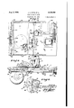
1938. J. E. PITTS El AL 2,125,459
BOOK SEWING MACHINE Filed Feb. 1'7, 1935 2 Sheets-Sheet l IN VEN TORS JOSEPH EDWARD P/TTS AR ALLAN Goa/.0
Aug. 2, 1938. J. E. PITTS ET AL 2,125,459
BOOK SEWING MACHINE Filed Feb. 17, 1936 2 Sheets-Sheet 2 1 N VEN TORS 7 QfOSEPH EOWARD Pxrr-S Epqnn ALLAN GauLa Patented Aug. 2, 1938 noon snwme MACHINE Joseph Edward Pitts, Oakland, and Edgar Allan Gould, Bruno, Calif.
Application February 17, 1936, Serial No. 64,206
4 Claims.
The present invention relates generally to an improvement in sewing machines for applying a tape to opposite sides of a stitched seam, and more particularly to an improvement which will facilitate the application of a binding tape to book.
sections in accordance with the-teachings of United States Patents No. 1,585,076, issued May '18, 1926, to Carl F. Emma and No. 1,989,290, issued January 29, 1935, to Joseph E. Pitts.
An object of the present invention is to provide an improvement for sewing machines, which will apply a tape to each side of the work and in line with the stitching produced by the machine.
Another object of the invention is to provide a simple, novel and convenient form of adjustable tape guiding means for aligning a tape with the stitching produced by a sewing machine.
Another object of the invention is to provide, in combination with a tape applying and stitching machine-of the character described, means which will maintain said tape under tension as it is stitched to the work.
A further and more specific object of the present invention is to provide a machine upon which the methods of binding disclosed in the above referred to Letters Patent may be conveniently and efliciently carried out.
Other objects and advantages of the invention will be in part evident to those skilled in the are and in part pointed out hereinafter as the description thereof proceeds. For the purpose of illustrating this invention there is shown in the accompanying drawings, by way of illustration and not of limitation, preferred embodiments of the several details thereof.
In the drawings wherein like numerals refer to like parts throughout the several views:
Figure 1 is a. perspective view of a machine embodying the invention,
Figure 2 is 'a fragmentary front elevation of the apparatus illustrated in Figure 1 of the drawin-gs,
Figure 3 is a fragmentary plan view of the apparatus illustrated in Figure 1 with the sewing machine head omitted,
Figure 4 is a slightly enlarged sectional view taken along line IVIV of Figure 3, looking in direction of arrows,
Figure'5 is a fragmentary perspective view showing details at the needle station of the sewing machine,
Figures 6 and 7 are perspective views of the tape feeding guides illustrated in Figure 5 of the drawings,
Figure 8 is a detailed perspective view of the tape twisting device through which one of the tapes is passed, and
Figure 9 is a fragmentary view partially in sec-' tion showing details of a tape tensioning device constructed in accordance with the invention.
For the purpose of describing the invention there is shown in the accompanying drawings a 10 sewing machine, designated by the numeral M, which is of a standard make. The particular machine illustrated is of the type in which the needle moves laterally to produce a zigzag line of stitching. However, it is to be understood that the 16 present invention is also applicable to sewing machines of the type which produce a straight line of stitching.
The sewing machine is preferably mounted upon a table or work bench ll, so that its bed- 20 plate l2 will lie flush with the top surface of the table II. The sewing machine ID has an overhanging head l3 that carries a needle bar it and a presser foot l5 through which a needle upon the needle bar it is adapted to pass. Below the presser foot l5 and beneath a removable work supporting plate i6 upon the bedplate I! of the sewing machine, there is the usual thread shuttle. Secured to the overhanging head l3 oi the sewing machine, there is a vertically extending bracket I1 that carries a tape reel housing i8, in which a reel of plain or glued tape I! may be supported and drawn therefrom.
In Figure 1 of the drawings the tape I9 is shown as extending from the housing l8 downwardly and as passing through a guide means 20, to be hereinafter described, which is carried by the presser foot l5. This guide means is adapted to direct the tape l9 to the top surface of the work, which, as illustrated in this figure of the 40 drawings, comprises a section of book-leaves, designated by the letter A, that is adapted to be bound with other similar sections of book-leaves to form a complete book, in accordance with the teachings of one-or the other of the above referred to Letters Patent. For this purpose the tape I9 is provided with a suitable adhesive upon its top surface, which can be moistened when the book sections are finally placed together to complete a book. Disposed slightly inwardly from the presser foot i5 there is a transversely extending guide means 2|, against which the edge of the book section A is adapted to be held during the stitching operation. Cooperating with the guide means 2|, there is a second and adjustable guide means 22 that is adapted to engage the opposite edge of the book section A and hold the book section firmly against the guide member 2|, so that the spacing of the stitching from the edge of the book section will be uniform throughout its length. The guide means 22 has an overhanging portion 23, under which the adjacent edge of the book section is adapted to pass, and immediately under this overhanging portion 23, the guide means 22 has a plurality of resilient pressure exerting elements which serve to equalize the pressure upon the book section as it passes" between the guide means 2| and 22 during-the stitching operation. This latter means is to be described in more detail hereinafter.
The guide means 22 is slidably supported upon the top of the table II- by means of overhanging brackets 24, each of which carry an underslung rack 25 that extends toward the machine head l3 and along the underside of the table 'I I. These racks 25 are suported at their free ends by means of cooperating gears 26, which are secured upon a transversely extending shaft 21 carried by the table I. The shaft 2! has a hand-operating knob 23, by means of which rotation may be imparted to the gears 23 for the purpose of moving the guide 'means 22 toward and away from the stationary guide means 2|. A set screw 23 is also provided adjacent the knob 23 for locking the shaft 21 against rotation after the guide means 22 has been properly positioned upon the table- I. Suspended below the table or work bench there is a drawer-like member 33 which is adaptbrackets 32, so that it will clear the rack t25 when it is drawn out for the purpose of placing a spool 3| thereupon. The tape reel supporting drawer 33 also has a suitable tape twisting guide mounted in one side thereof, which is adapted to take a tape, designated by the numeral 34, from the reel 3|, in a vertical edgewise position and deliver it to the top surface of the bedplate l2 in a horizontal edgewise position. the drawings this twisting guide 33 is shown as pulled out, with the drawer 33 beyond the near edge of the work table II, but it will be understood that when the machine is in operation, the discharge end of this twisting guide 33 will be disposed immediately belowa notch 35 formed in the edge of the bedplate l2 adjacent the stationary guide means 2i. From this latter point the tape 34 will progress over the bedplate l2 and through a suitable guide means which is adjustably secured upon the movable cover plate It, as will be hereinafter described. Then as the work is passed through the sewing machine it will be superimposed upon the tape 34, and the latter will be stitched to the underside of the work simultaneously with a stitching of the tape I! to the upper side of the work. The tape 34, like the tape l3, will be provided with an adhesive when the tape is to be used for the purpose of binding a plurality of book sections together. In this latter instance the tape 34 will pass through the machine with its adhesively treated side disposed away from the book sections to which it is stitched.
In addition to the above described'expedients, the present invention also contemplates an auxiliary work feeding and tape tensioning means, which comprises cooperating rollers 33 and 31 In'Flgure 1 of that extend transversely across the line of the stitching produced by the sewing machine. These rollers 36 and 31 are driven in a novel manner and rotate in a direction which will produce a pull upon the tapes l3 and as the work progresses through the sewing machine. This auxiliary work feeding aspect of the present invention and its mode of operation is to be described in greater detail hereinafter, in connection with other figures of the drawings.
With the ararngement above described, it will be seen that after the book sections have been made up to a proper thickness, and the tapes Ill and 34 have been started through their respective guides upon the sewing machine, the book sections may be successively fed between the guide means 2| and 22, and under the sewing machine head l3, so that the tapes l9 and 34 will be si-,
multaneously sewed respectively to the top and bottom sides of the book sections A in a continuous manner. Then as a final operation, the book sections may be separated by cutting the tapes therebetween, and finally arranged in proper order, moistened and pressed into complete book units.
Upon again referring to Figure 2 of the drawings, it will be seen that the work supporting table or bench II also carries a suitable driving motor 33 having pulleys 33 and 40 that are adapted to be connected to the motor by means of a clutch 4|. The frame of the motor 33 carries a bracket 42 upon which there is pivoted a clutch operating lever that is adapted to be operated through a connecting rod 44 by a foot pedal, not shown. Adjacent the motor 38, the table II also supports a suitable motor speed controller 45, which is adapted to be operated by a knee engaging plate 46. As here shown,-the pulley 33 operates through a belt 41 to drive the sewing machine, and the pulley 40 operates through a belt 43 to drive a pulley 49 that is secured upon the end of a shaft 50, and which, as will hereinafter appear, serves .to drive the rollers 36 and 31 of the work advancing and tape tensioning mechanism.
As shown in Figure 3 of the drawings, the shaft 50 is journaled upon the underside of a plate 5|, which is recessed in the top of the table II so that its upper surface is flush with the top of the table. In this figure of the drawings, the tape reel supporting drawer 3|] is shown as positioned in its proper operating position, with the outwardly extending tape twisting guide 33 disposed, with its discharge end, immediately below the notch 33 formed in the edge of the bedplate l2 of the sewingmachine. This figure of the drawings also shows the details of a preferred form of the yielding pressure producing means, previousmeans comprises a plurality of pivotally mounted arms 52, which swing in ahorizontal plane in response to the action of suitable springs 53, and at their outer ends these pivotally mounted arms 52 each carry a vertically disposed roller 54 which is adapted to roll against the edge of the book section as it passes through the machine.
Figure 4, like Figure 3, also shows the tape twisting guide 33, through which the tape 34 is guided to the needle station of the sewing machine, as in its operative position. This figure of the drawings also illustrates how the shaft 21 and the gears 26 are mounted upon the underside Reference is now made to Figures 5, 6 and 7 of the drawings, for a detailed description of the tape guiding means previously referred to as carried by the presserv foot l and the shuttle covering plate l6 of the sewing machine It. As shown in Figure 5 of the drawings, the presser foot l5 has an upwardly extending end 55 upon which the tape guiding means 23, illustrated in detail in Figure 6, is adjustably secured, and the cover plate It is shown as having a tape guiding means 55, which is adjustable for alignment with a needle aperture 51 in the cover plate N. This adjustable guide 55 is illustrated in detail in Figure '7 of the drawings. The tape guide 30 is held upon the presser foot l5 by means of screws 58, and is adjustable laterally, so that it will center the tape l9 with respect to the needle bar l4 of the sewing machine. The guide 53 has an underhanging extension 55- which is recessed into the bottom of the cover plate l3, and where it is adjustably secured by means of a screw 53, so that it may be moved laterally upon the cover plate to center the tape 34 over the needle aperture 51. The cover plate l5 also has apertures 50 and BI through which the usual work feeding elements 52 of the sewing machine project. Extending from the notch 35 in the side of the bedplate l2, and over the top surface of the cover plate l5, there is a recessed groove 63 through which the tape 34 may freely move in its travel to the adjustable guide member 56 upon the cover plate It. This groove 53 prevents the tape 34 from contacting the underside of the work until it reaches a point immediately in advance of the needle station of the sewing machine, and the disposition of the tape guide 20 upon the presser foot I5 is such that it also provides against the tape l9 contacting the work until it reaches a point immediately in advance of the needle station of the sewing machine. Upon referring to Figure 6, it will be seen that theguide 20 has a narrow aperture extending therethrough, which is substantially equal to the dimensions of the tape I 9, and upon referring to Figure 7 of the 1 drawings, it will be seen that the adjustable guide 55 has an aperture 65 which corresponds to the dimensions of the tape 34. The guide means 20 and 56 above described, are made readily detachable from their respective supports so that other and similar guides may be substituted therefor when tapes of different widths are to be used upon the sewing machine.
Reference is now made to Figure 8 of the draw ings for a detailed description of the tape twisting guide 33, which serves, as previously stated, to turn the tape 34, as it is taken from its horizontally disposed reel 3|, into a horizontal edgewise position for introduction into the aperture 65 of the guide means 55. As here shown, the twisting guide 33 has a rounded end 56 which directs the tape 34 from the reel 3| into a narrow slot 51 that extends through the guide 33. At the other end of the guide 33 there is a rounded or curved surface which is disposed at an angle of 45, so that as the tape 34 is carried therearound in a spiral path, it can be brought out through a vertical slot 68 at the end of guide 33, with its surfaces in a plane at right angles to the surfaces of the tape as it is taken from the reel 3|. This twisting guide 33 is shown in the drawings as secured upon the drawer-like reel supporting member 33, so that it may be pulled out with the supporting member 30 to facilitate a threading of the tape therethrough, and then pushed back into an operative position in line with the notch 35, previously described as formed in the bedplate II of the sewing machine.
The details of the tape pulling and tensioning device previouslyreferred to, will now be described in connection with Figure 9 of the drawings. As
here shown, the shaft 50 is journaled at its end upon a downwardly extending bearing bracket 53, which also provides a bearing support for the roller 33. The shaft 50 has a gear 1|! that meshes with and drives a similar gear 1| carried by the roller 33. 5| there is also a pair of axially spaced bearing brackets 12, upon which a countershaft 13 having an idling gear 14 is supported. Pivotally mounted upon the shaft 13 there is also a supporting housing 15 in which there is journaled a shaft 15 which carries the roller 31. This shaft 15 also carries a gear 11 which is constantly in mesh with the idling gear 14 upon the countershaft 13. With this arrangement it will be seen that when the shaft 5|] is rotated in the direction indicated by the arrow, the other gears and the rollers 36 and 31 will also rotate in thedirections indicated by arrows, and as a result the idling gear 14 will exert a downward pressure upon the teeth of the gear 11,'which will increase in proportion to any resistance offered to a rotation of the roller 31,
and consequently the roller 31 will be constantly urged downwardly toward the roller 35, so as to exert a pinching force upon the edge of the book section A as it passes therebetween. In order to produce this downward or pinching action in the roller 31, it is necessary for the surfaces of the rollers 35 and 31 to move at a relatively greater linear speed than the work. Therefore the shaft 50 is rotated at a speed which will produce alinear speed at the periphery of the rollers 36 and 31 which is greater than the speed of the book section passing therebetween. This produces a pinching action between the rollers 36 and 31 whichmay also be said to be dependent upon the coefficient of friction between the tapes at the edge of the book section and the rollers 35 and 31. If the rollers are slightly roughened, this pinching action will, of course, be greater than when the rollers have a polished surface. In practice it has been found that the rollers 38 and 31 operate satisfactorily when they have a smooth but unpolished surface.
With the above arrangement it will be readily seen that when the tapes I9 and 34 have been threaded through the guides at the needle station of the sewing machine l0 as above described, the book sections A may be conveniently passed therethrough in substantially the same manner as would be the case in a simple stitching operation. It will also be seen that when a series of book sections have progressed through the machine to a point where the rollers 35 and 31 engage the tapes l9 and 34, a pulling force will be constantly exerted upon these tapes which will pull them from their supply reels and through the machine with the work, independently of the work advancing mechanism 52 of the sewing machine. A further advantage obtained by the roll- Extending upwardly from the plate ers 35 and 31, which results from the fact that out or smoothed upon the book sections in a desirable manner.
While we have, for the sake of clearness andin order to disclose the invention so that the same can be readily understood, described and illus- 'trated specific devices and arrangements, we desire to have it understood that this invention is not limitedto the specific means disclosed, but
may be embodied in other ways that will suggest themselves to persons skilled in the art. It is believed that this invention is new and it is desired to claim it so that all such changes as come within the scope of the appended claims are to be considered as part of this invention. 15
Having thus described our invention, what we claim and desire to secure by Letters Patentis- 1. In a sewing machine of the c'haracteruiescribed, the combination of a work supporting table having an overhanging presser foot and needle beneath which the edge of a book section to be stitched may pass, a guide upon said work supporting table adjacent said presser foot for guiding the book section over said table with one edge beneath said presser foot and needle, a second guide means extending across the work supporting table in spaced parallel relation with said first guide adapted to engage the opposite edge of the book section and hold the stitchededge of the book section against said first guide as the stitching proceeds, a rack secured to each end of said second guide and extending toward said first guide, and a manually rotatable shaft extending parallel to said first guide having gears engaging said racks, whereby saidsecond guide may be adjusted while maintaining a parallel reiation between said guides by a rotation of said shaft.
2. In a sewing machine of the character described, the combination of a fixed horizontally disposed roller disposed with its axis extending transverse to the direction of the work passing through the sewing machine over which the work is adapted to pass, a driving shaft having a geared driving connection with said roller: an
idling gear adapted .to be driven by said driving shaft, a support mounted to move about the axis of said idling gear, and a second roller disposed above said first roller with its axis parallel thereto adapted to be driven in a direction complementary to said first roller by said idling gear to produce a pulling action upon the work passing .between said rollers, the peripheral speed of said rollers being slightly greater than the speed of the work passing therethrough, whereby the work will exert a retarding force upon the rollers and cause said second roller to move with its support about the axis of said idling gear'and producea pinching smoothing action upon the work as it advances therebetween.
3. In a sewing machine of the character described, the combination ci' a sewing machine of conventional type, means associated with said sewing machine fer directing a tape to each side of the work in line with the stitching produced by said machine, a roller disposed in the path of the ,work after being stitched having a driving gear and adapted to be positively rotated in a work feeding'direction, a second roller disposed above said first-roller mounted upon a floating shaft extending parallel with the'axis of said first roller, said floating shafthaving ,a gear mounted thereupon andbeing adapted'to move Y about the axis of a countershaft, a gear upon said countershaft associated with the gear upon said floating shaft, and a driving gear meshing with the gear upon said countershaft and theclriving gear upon said first roller adapted to impart a complementary work pulling rotation to said rollers and cause said floating shaft with said second roller to be moved downwardly and into pressure producing relation with the work as the pulling,
force exerted upon the work by said rollers is resisted! 4. In a. work pulling device for a machineof the character described, the combination of a fixedroller having its axis disposed transverse to the direction of travel'of work thereover, a
driving shaft disposed in spaced horizontal relation with said roller, 9. gear drive between said roller and said driving shaft, a countershaft dis- JOSEPH EDWARD Prrrs;
Priority Applications (1)
| Application Number | Priority Date | Filing Date | Title |
|---|---|---|---|
| US64206A US2125459A (en) | 1936-02-17 | 1936-02-17 | Book sewing machine |
Applications Claiming Priority (1)
| Application Number | Priority Date | Filing Date | Title |
|---|---|---|---|
| US64206A US2125459A (en) | 1936-02-17 | 1936-02-17 | Book sewing machine |
Publications (1)
| Publication Number | Publication Date |
|---|---|
| US2125459A true US2125459A (en) | 1938-08-02 |
Family
ID=22054283
Family Applications (1)
| Application Number | Title | Priority Date | Filing Date |
|---|---|---|---|
| US64206A Expired - Lifetime US2125459A (en) | 1936-02-17 | 1936-02-17 | Book sewing machine |
Country Status (1)
| Country | Link |
|---|---|
| US (1) | US2125459A (en) |
Cited By (6)
| Publication number | Priority date | Publication date | Assignee | Title |
|---|---|---|---|---|
| US2655884A (en) * | 1950-06-08 | 1953-10-20 | Rohrlick Michael King | Apparatus for automatically feeding and stitching slide fastener stringers to garment fly pieces |
| US2672111A (en) * | 1950-09-22 | 1954-03-16 | Widrow Jacob | Sewing machine guide |
| US2723636A (en) * | 1953-02-19 | 1955-11-15 | Galkin Joseph | Elastic metering attachment for sewing machines |
| US2885979A (en) * | 1954-07-20 | 1959-05-12 | Willcox & Gibbs Sewing Machine | Means for securing a band loop to an article |
| US4479449A (en) * | 1983-04-14 | 1984-10-30 | Raiche Rejean | Differential feed type sewing machine |
| US5054407A (en) * | 1990-03-20 | 1991-10-08 | Rowley Clare J | Presser foot having an adjustable guide for sequin and ribbon |
-
1936
- 1936-02-17 US US64206A patent/US2125459A/en not_active Expired - Lifetime
Cited By (7)
| Publication number | Priority date | Publication date | Assignee | Title |
|---|---|---|---|---|
| US2655884A (en) * | 1950-06-08 | 1953-10-20 | Rohrlick Michael King | Apparatus for automatically feeding and stitching slide fastener stringers to garment fly pieces |
| US2672111A (en) * | 1950-09-22 | 1954-03-16 | Widrow Jacob | Sewing machine guide |
| US2723636A (en) * | 1953-02-19 | 1955-11-15 | Galkin Joseph | Elastic metering attachment for sewing machines |
| US2885979A (en) * | 1954-07-20 | 1959-05-12 | Willcox & Gibbs Sewing Machine | Means for securing a band loop to an article |
| US4479449A (en) * | 1983-04-14 | 1984-10-30 | Raiche Rejean | Differential feed type sewing machine |
| US5054407A (en) * | 1990-03-20 | 1991-10-08 | Rowley Clare J | Presser foot having an adjustable guide for sequin and ribbon |
| WO1992004494A1 (en) * | 1990-08-30 | 1992-03-19 | Rowley Clare J | A presser foot having an adjustable guide for sequins and ribbon |
Similar Documents
| Publication | Publication Date | Title |
|---|---|---|
| US2266538A (en) | Flat elastic feeding device for elastic attaching sewing machines | |
| US2702067A (en) | Machine for making covered apparel belts | |
| US2125459A (en) | Book sewing machine | |
| US2797656A (en) | Sewing apparatus and methods | |
| US3160124A (en) | Means for making mattress border panels with welted edges | |
| US1857371A (en) | Mechanism for sewing mattresses | |
| US2256793A (en) | Sewing machine and attachment therefor | |
| US2198345A (en) | Apparatus for and method of making fasteners | |
| US2268414A (en) | Sewing machine | |
| US3799082A (en) | Machine for simultaneously sewing the opposite edges of strip material | |
| US1988241A (en) | Seam opening and wind-up device | |
| US2350027A (en) | Method of making bias fabric | |
| US2430463A (en) | Strip edge infolding machine | |
| US2757624A (en) | Sheet hemming and hemstitching apparatus | |
| US3731330A (en) | Book binding | |
| US2150527A (en) | Feeding mechanism for sewing machines | |
| US2170948A (en) | Sewing machine | |
| US2281308A (en) | Mechanism for the manufacture of comfortables, quilts, and the like | |
| GB712486A (en) | Improvements in and relating to sewing machines | |
| US5694875A (en) | Border serger | |
| US2113457A (en) | Machine for closing and positioning springs in pockets | |
| US2339179A (en) | Apparatus for making corded-edged textiles | |
| US1608944A (en) | Duplex sewing machine | |
| US1832636A (en) | Machine for making rugs, coverings, and the like | |
| US1913878A (en) | Attachment for sewing machines |