US2125258A - Grease dispensing apparatus - Google Patents
Grease dispensing apparatus Download PDFInfo
- Publication number
- US2125258A US2125258A US705562A US70556234A US2125258A US 2125258 A US2125258 A US 2125258A US 705562 A US705562 A US 705562A US 70556234 A US70556234 A US 70556234A US 2125258 A US2125258 A US 2125258A
- Authority
- US
- United States
- Prior art keywords
- grease
- container
- rod
- ram
- generally
- Prior art date
- Legal status (The legal status is an assumption and is not a legal conclusion. Google has not performed a legal analysis and makes no representation as to the accuracy of the status listed.)
- Expired - Lifetime
Links
Images


Classifications
-
- F—MECHANICAL ENGINEERING; LIGHTING; HEATING; WEAPONS; BLASTING
- F16—ENGINEERING ELEMENTS AND UNITS; GENERAL MEASURES FOR PRODUCING AND MAINTAINING EFFECTIVE FUNCTIONING OF MACHINES OR INSTALLATIONS; THERMAL INSULATION IN GENERAL
- F16N—LUBRICATING
- F16N3/00—Devices for supplying lubricant by manual action
- F16N3/10—Devices for supplying lubricant by manual action delivering grease
- F16N3/12—Grease guns
Definitions
- l' ⁇ vMy invention relates to a certain new and useful improvement in the art of dispensing grease, and it relates more particularly to so-called packaged grease, that is, grease put up in relatively small containers which are sealed by the manufacturer of the grease, and from which the Agrease is dispensed directly into the automobile part, such as the transmission, or differential, o r free-wheeling unit of the automobile.
- the object of my invention is to provide an Voriginal container for grease and an ejector means adapted to cooperate therewith, whereby the grease may be ejected from the original container in an efficient and facile manner without l5 waste or loss of grease, and whereby the container may not again be re-iilled after its original contents has been discharged.
- Figure 2 represents a section generally on line v ⁇ 2-2 of Figure 1.
- Figure 2-a represents: a sectional view on line 'Y 2-a2-a of Figure 1.
- Figure ⁇ 3 represents a section generallyv on line V'3--3 of Figure 1.
- Figure 4 represents an end view of the can grip- 15 per and grease expeller with the can removed.
- f- Figure 5 represents a perspective view of the can seal.
- Figure 6 represents a sectional view of the bottomA of a can of a modified form of construction embodying my invention.
- Figure l represents a longitudinal sectional view of a can gripper and eXpeller, and a can held f1 thereby, showing a modified embodiment of my invention.
- Figure 8 represents a plan view of the handle of the ejector shown in Figure 7, with the outer washer partly broken away so as to expose to view the one-way clutch within the handle.
- Figure 9 is a plan View of the metal follower plate or piston-like member shown in Figure 7.
- Figure 10 is a sectional view of a non-metallic packing disc or follower member similar to that shown in Figure 7, but of a somewhat modified construction.
- FIG. 11 represents a partially sectioned view 10 of a modied form of device embodying my invention.
- Figure l2 represents: a fragmentary sectional View of a construction similar to that shown in Figure 1 in which frictional engagement is pro ⁇ 15 vided between the operating lever and the ram rod.
- Figure 13 represents a sectional view similar to that shown in Figure 1 of a further modified embodiment of the present invention.
- Figure 14 represents a fragmentary side elevational view of the same.
- Figure 15 represents a bottom plan View of the same.
- I provide an original sheet metal container or can I5 of any suitable cross-section, but preferably of a generally cylindrical formation, as indicated in Figure 1, including the side wall I6, the end member Il permanently fastened thereto by any conventional means, as for instance the turned seam I8, and
- the bottom end member is provided with a central opening 2l which is surrounded by an outwardly projecting and more or less cylindrical flange 22.
- a sheet metal sealing member or bottom-forming plug 23 is provided within the can.
- bottom-forming plug member 23 When the bottom-forming plug member 23 is thus in place and irictionally gripped within the hanged opening 2l of the bottom of the can, it serves as a removable seal for said bottom opening, but is removable from the flanged opening 2l only in an inward direction indicated by the arrow 29.
- a follower disc or piston-like member 38 is provided, preferably of sheet metal orthe like, having an annular flange 3i, which is adapted more or less snugly or loosely to fit within the cylindrical wall i6 of the can, sothat any movement of the follower disc or pistonlike member 36 in the direction of the arrow 29 will force the contents of the can also in the direction of the arrow 29 without leaving behind any appreciable amount of the material.
- the follower disc or piston-like member 30 (in the embodiment of the invention shown in Figure 1) is provided with a socket-like reces-s 32, disposed centrally with respect to the disc, which may have a closed end 33, or which may be open at its inner end, thereby merely leaving an annular inwardly extending flange to surround the inwardly projecting portion 24 of the bottom-forming plug 23.
- Either the plug 23 per se, or the lpiston 38 and associated plug 23 jointly, may be considered to constitute a bottom portion which coacts with the end portion i9 to form a composite bottom for the container.
- the top end member l1 of the container I5 is preferably provided with a screw-threaded neck 34, which may be fastened thereto by any suitable means, as for instance, by soldering at 35, or by other suitable means known in the canmaking art.
- the screw-neck 34 is adapted to receive a corresponding screw-cap 36 having any suitable sealing gasket 31 therein, for effecting a grease-proof seal.
- the can is assembled with the plug 23 in place, as indicated in Figure 1, and with the follower member 38 in its bottom-most position, also indicated generally in Figure 1, and with the screwcap 36 removed.
- the can is then filled with a predetermined amount of grease, of the particular grade and kind desired, and the screw-cap 36 then applied tightly to the screw-neck 34, thereby to form a grease-proof seal.
- the sealing member shown in Figure 5, and designated generally by the numeral 38 is superimposed upon the screw-cap with its depending leg portions 33 soldered to the end member I1 as at 48.
- the ejector 42 adapted generally to coact with the container i5, includes a can gripper portion and a ram-rod and actuating means therefor in operative relation to the can gripper portion.
- a base plate 43 or an equivalent structure is provided, including the stationary bead-engaging member 44, of more or less arcuate shape and integrally or otherwise xedly related to the base or equivalent structural member 43, and a movable bead-engaging member 45 at a point more or less diametrically opposite to the beadengaging member 44.
- the movable bead-engaging member 45' may be pivoted at 46 to any suitable webbing or other structural member 41 integrally or otherwise xedly related to the member 43, and yieldably held in an engaging position by any suitable spring 48.
- the members 44 and 45 are adapted to engage the slight annular bead-like seam 29 surrounding the bottom end of the can, thereby to hold the can fast and in predetermined relation to the ram-rod 49, which extends through the member 43 at generally a right angle thereto, and
- the ram-rod is provided with a series of spaced annular grooves 58 throughout its length, with the exception of the innermost terminal portion thereof, which is adapted to project into and contact with the plug member 23.
- the annular grooves 50 include the more or less vplane annular surfaces 5
- the rod 49 is slidably mounted within a suitable bore 54 of the guide member 55, which is also preferably integrally or otherwise Xedly related to the member 43 which carries the beadengaging members 44 and 45.
- a stationary handle 56 is xedly secured to the member 43 by riveting or otherwise fastening it to the web 41, as at points 51. If desired, the handle 56 may be also formed Vintegrally with the web 41 and hence, with the member 43 which carries the bead-engaging members 44 and 45.
- the handle 56 is preferably of a slightly dished cross-section as indicated in Figure 3, and eX- tends along the ram-rod 49, and tends to protect the same against injury in handling and operation of the ejector.
- the movable handle 58 is preferably pivoted to the member 43, as for instance, by means of the pivot 59 extending through said handle 58 and through the pivotal lug or hinge member 60, which is also integrally or otherwise xedly o1' stationarily related to the member 43, and hence, to the bead-engaging members 44 and 45.
- vis provided in the han-dle 58, for slidably receiving the pawl 53.
- the pawl 53 is provided with an extension rod 62, which is preferably screw-threadedly secured thereto, which extends through the handle and terminates in the knob 63.
- the knob 63 includes a lateral pin or similar lateral projection 64 which slides in suitable slots, and which, when raised clear of said slots and disposed transversely, will keep the pawl 53 in a retracted and inoperative position in relation to the ram rod 49.
- the spring 65 acts upon the pawl 53 to maintain it in resilient contact with the ram rod 49 when the transverse lug or pin 64 is not so disposed as to keep the pawl in the retracted position.
- Any suitable spring such as the spring 66, tends to displace the handle 58 in the opening direction indicated by the arrow 61.
- the seal 38 is removed from the can and the screw-cap 36 also removed therefrom, andthe can held in operative position between the bead-engaging members 44 and 45, as shown in Figure 1.
- the device is gripped in one hand in the manner in which pliers are generally gripped, and the handle 58 pressed towards the handle 56 repeatedly, thereby causing the ram-rod 49 to be Vadvanced in the direction of the arrow 29.
- the 'rst advance causes the dislodgment of the plug 23 from its frictional engagement with the flanged opening 2
- This operation may be continued until the entire contents has been displaced, whereupon the empty can is removed from between the bead-engaging members 44 an-d 45, and is discarded, as it cannot be thereafter re-lled.
- the insertion and removal of the can is effected by depressing the handle-like portion 68 of the member 45 in the direction of the arrow 69.
- a discharge spout such as illustrated partticularly in Figure '7, may be screwthreadedly affixed to the screw-threaded neck 34 of the cam i5 during the discharge operation.
- This spout is particularly desirable where it is desired to expel and dispense the grease into some more or less inaccessible or inconveniently located opening, as for instance, the re-fill opening of the transmission, differential, or free-wheeling units of an automobile.
- FIG 6 I have illustrated a modified form of container construction embodying my invention, wherein the plug and follower piston are made integrally with each other thus jointly constituting a bottom portion cooperating with the end portion I9.
- the plug 23 and piston 30 are formed in continuation of each other.
- the ram-rod 49 is shown provided with tooth-like recesses, for positive engagement by a pawl, it is to be understood that the engagement between the movable handle and the ram-rod may be of a frictional character, instead of as the positive character shown.
- the rod may be advanced in the direction of the arrow 29, by causing the handle 58 to push the friction gripping member off-center, in the direction of the arrow 29, thereby cooking or inclining said friction gripping member in relation to the ram-rod, and causing frictional engagement between the two.
- Any suitable spring may then be provided for returning the friction gripping member to its initial position. By placing the spring more or less coaxially with relation to the aperture in the friction gripping member, the latter may be returned to its original position without any frictional engagement with the ram-rod.
- the ramrod is advanced by means of a handle 13 which may be fixedly or otherwise secured to the outerv end of the ram-rod 19.
- a handle 13 which may be fixedly or otherwise secured to the outerv end of the ram-rod 19.
- a handle 13 is so mounted upon the outer end 14 of the ram-rod l0, as to rotate freely with respect to the ram-rod in one direction, and frictionally to grip the ram-rod when rotated in the opposite direction.
- a sleeve-like bushing 'l5- is secured (against rotation) by means of any suitable locking pin 16.
- the bushing 'l5 is provided with a lateral flange ll.
- the handle 13 is provided with a central opening 18, of generally the same diameter as the outer diameter of the bushing l5, and immediately adjacent said opening, is also provided with a pair of roller chambers 19, in diametri-1 cally opposite relation to each other.
- the chambers 19 have outer inclined or eccentric camming surfaces 89.
- is interposed between the surface and the cylindrical surface of the bushing T5, and is yieldably urged in the direction of the intended rotation of the ram-rod, to wit, in the direction of the arrow 82, by means of the springs 83, acting through suitable roller-engaging blocks 84.
- the cover plate held in place by the screw 86 serves to hold the handle and rollers in assembled relation to each other, and to the ram-rod.
- the screw-threaded ram-rod is caused to rotate in a direction which will urge said rod forwardly in the direction ofi the arrow 29.
- the handle When rotating the handle in the opposite direction (arrow 82) the handle is moved independently of the ram-rod.
- the ram-rod may be advanced by'repeated oscillations of the handle, without the necessity of taking a new grip on the handle with each operation.
- the contact end of the ram-rod 10 is preferably devoid of the screw-threads 'H and the bushings 12 or equivalent member, is preferably recessed as at 88, for a depth sufficient to receive the thread-free contact end of the ram-rod 18, so that the ram-rod may be retracted completely, or at least to a point where it is fully receded from the plug or follower member. great inclination of the thread 1I, the ram-rod may be moved back to its initial or outer position merely by pushing it through the bushing in a direction opposite to the arrow 29.
- Any suitably curved or straight spout 89, of any desired length, may be provided, having a screw-threaded coupling member 99 at one end thereof, adapted threadedly to engage the screwthreaded neck 34 of the can l5.
- may also be provided,
- the nozzle or spout 99 may be of any suitable piece of tubing which is extended through a corresponding opening 92 in the coupling member 99 and is soldered" i;
- the metallic follower plate 95 is provided with an aperture 96, preferably slightly flared in the direction of the arrow 29, and adapted snugly to t over the cylindrical portion 24 of the bottom-forming plug 23. If desired,
- the follower plate 95 may also be provided with?” the annular flange 3l similar to that indicated in Figures 1 and 6.
- I may also provide a suitable number of spaced radial flutes in the sheet metal plate 95 thereby to give greater rigidity to the:
- the plate is preferably also slightly dished as indicated in Figure 7.
- I may also provide a non-metallic packing disc which may ber Because of thel in the forni of a sheet of cardboard, or may be a cardboard center 98, having a relatively thin and more or less grease-resistant sheets of paper or similar material 99 and Ilm on either side thereo-f.
- a metallic retainer plate ISI having a central aperture EQ2 fitting snugly over the member 24 of the plug 23, serves to hold the packing disc in assembled relation to the piston-like member 95 (or 3i!) and the plug 23.
- the non-metallic packing disc consisting either of the sheet of cardboard 9S, or' a piece of cardboard 98 flanked on either one or both sides by a sheet of more or less firm and more or less grease-resistant 'cheap material such as S9 and Iii, is tted snugly within the cylindrical shell I@ of the can I5, so that more complete removal of the grease is made possible.
- this non-metallic packing disc a more accurate contact is obtainable between the piston assemblage and the cylindrical wall of the can.
- the annular flange 3l of the metallic follower piate 95 is shown slightly spaced from the cylindrical wall of the can.
- flange i-Il3 formed of paper or other similar material, is sufficiently form-retaining to have the effect of a cup-washer, with the pressure of the contents tending to force it against the cylinder wall, yet it is sufliciently flexible to be crushed and flattened out' against the end of the can Aso that the last bit of grease may also be expelled from the can.
- FIG. 1l a further modified form of piston unit is shown, in which a cup-shaped paper disc m5 is used alone. in conjunction with a metallic follower plate, such as the follower plate 95 or 3i).
- a suitably form-retaining paper or other fibrous material may be provided in a generally cup-shape having the ilange which will be forced against the cylinder wall by any slight grease pressure while the grease is being expelled, and which will at the same time, be flattened out and crushed against the end of the can during the last portion of the stroke of the piston, so
- one of the principal objects of my present invention is to provide means whereby original containers of grease may be emptied directly into the point of ultimate use, by expelling meansr cooperating with the can, and whereby cans of varying length may be used in conjunction with the same expelling member.
- the springs 48 tend to deflect the guides I I2 and hence the members I lil in an engaging direction.
- the members IIB are preferably provided with a series of teeth along their outer or inner surfaces designated generally by the numeral H5, which are adapted to be engagedby the pawl IIS, yieldably pressed into Vcontact therewith by the spring IIT.
- the pin I i8 extending transversely through the rod-like extension Il!! of the pawl IIi, is adapted to slide invand out in a slot IZB of suicient depth to permit the pawl Il@ to engage the teeth I I5.
- ⁇ A pair of shaliower recesses IZI are also provided at a right angle to the slot IZB, for receiving the pin H8 when it is desired to retain the pawl I I6 in a retracted and inoperative position. This may be effected by pull- I22, and turning the knob L tion, the pawl retains the members H0 in place,v Y and the grease may1 then beY expelled by the operation of the handle 124.
- the handleY I2@ is similar to the handle 73, except it is provided with an annular rim
- I may provide a plurality of movable bead-engaging members similar to the member 45, in place of the stationary member 44. So too, in the embodiment shown in Figure 1l, I may provide one or more of the guides 2 in fixed relation to the member 43 instead of in pivotal relation thereto.
- 26 is surrounded at one point by a friction plate
- 30 tends to return the friction plate
- the member 43 is similar to the member 43 shown in Figure 1, except Ythat a deep recess
- I have also shown the member 43 of. a substantially greater depth or transverse dimension.
- Grease dispensing apparatus comprising an original grease container having a generally cylindrical body and having endeopenings at its opposite ends, closure means closing the upper ond-opening, inwardly movable but non-removable closure means associated with the bottom end-opening, said latter closure means including two separate annular portions, one a generally cylindrical flange-like annular portion for frictionally gripping and sealing with the bottom endmopening while the container is in storage or transit and prior to actual use, and the other an annular portion for engagement with the cylindrical side-wall of the container during operative inward movement of said closure means, said latter closure means being adapted to be moved out of sealing relation to the bottom end-opening and to be moved inwardly in operative relation to the side-wall of the container to dispense the grease of the container in the direction of the upper end thereof, and an annular ange member parallel with said first-mentioned annular portion of said inwardly movable closure means, said last-mentioned annular flange member dening said bottom end-opening
- Grease dispensing apparatus comprising an original grease container having a generally cylindrical body and having end-openings at its opposite ends, closure means closing the upper end-opening, inwardly movable but non-removable closure means associated with the bottom end-opening in frictionally gripped and sealed relation while the container is in storage or transit, said latter closure means including two separate annular portions, one for frictional gripping and sealing engagement with the bottom.
- said latter closure means being adapted to be moved out of sealed relation to the bottom end-opening and to be moved inwardly in operative relation to the cylindrical side-wall of the container, to displace the grease content of the container in the direction of the upper end-opening, and manuallyoperable ejector means adapted detachably to engage an end of said container and to advance said inwardly movable means in the direction of the upper endopening; said ejector means including means adapted to extend through said bottom endopening of the container.
- Grease dispensing apparatus including the combination with an original grease package comprising a can having a sheet metal bottom member capable of having a portion thereof moved inwardly, said bottom member being permanently secured to the side-wall of the can by means or an inter-folded and inter-locking peripheral seam at the terminal of the side-wall of the can, said seam projecting laterally to a slight extent at said terminal and constituting a peripheral bead at the bottom end of the can, of ejecting means adapted to cooperate with said can, said ejecting means including a plurality of bead-engaging means movable with relation to each other and adapted detachably to interlock With and engage said peripheral bead of said can, a ram rod carried by said ejecting means and slidably mounted generally at a right angle to the plane of said bead-engaging means, said ram rod being located generally coaxially with respect to the eiective circle of said bead-engaging means, and means for intermittently advancing said ram rod to
- Grease dispensing apparatus including the combination with an original grease package comprising a can having a sheet metal bottom member capable of having'a portion thereof moved inwardly, said bottom member being permanently secured to theY side wall of theY can by means of an inter-folded and inter-locking peripheral seam at the terminal of the side Wall of the can projecting laterally to a slight extent at said terminal, and constituting a peripheral bead at the bottom end of the can, of ejecting means adapted to cooperate with said can, including a plurality of bead-engaging means movable with relation to each other and adapted detachably to interlock with and engage said yterminal bead of said can, a ram rod carried by said ejecting means and slidably mounted generally at a right angle tothe plane of said bead-engaging means and being located generally coaxially With respect to the effective circle of said bead-engaging means, and means for intermittently ⁇ advancing said ram rod, said ram rod advancing means having means whereby it
- Grease dispensing apparatus including the combination with an original grease p-ackage comprising a can having aV sheet metal bottom memberV capable of having a portion thereof moved inwardly, said bottom member being permanently secured tothe side-wall of the can byn means of an inter-folded and inter-locking peripheral seam at the terminal of the side-wall of the can, said seam projecting laterally to a slight extent at said terminal and constituting a peripheral bead at the bottom end of the can, of ejecting means adapted to cooperate with said can, said ejecting meansiincluding bead-engaging means adapted detachably to interlock with and engage said peripheral bead of said can, a ram rod carried by said ejecting means and slidably mounted generally at a right angle to the planeY of said bead-engaging meansfsaid ram rod being located generally coaxially with respect to the eiective circle 'of said bead-engaging means, and manually operable means movable in a direction generally trans
- Grease dispensing apparatus comprising an original grease container having a generally cylindrical body and end-openings at its opposite ends, a movable head portion originally gripped in the bottom end-openingY of said container in sealed relation thereto, said head portion having a central inwardly projecting socket, and means adapted to engage said container independently of the end wall thereof and further adapted to from the container, said means including la ram rod adapted toenter said socket, and means for forcing said ram rod longitudinally of said container to move said head portion inwardly.
- a grease container having a grease expelling piston element originally associated with the bottom thereof, meansfor moving said grease expelling piston, said means comprising in combination a pivoted handle, meansfor attaching said handle to they means whereby said pawl may be disabled by pulling said rod to withdraw said pin from its slot and turning the pin to hold the pawl in withdrawn position.
- Grease dispensing apparatus comprising an original grease container having a side-wall and having end-walls permanently affixed thereto and having an end lopening in each of its opposite end-walls, means adjacent the 1bottom end-wall v of said container and adapted for lquick detachable and attachable engagement with said container independently of said bottom end-wall, said means including a plunger to expel grease from said container, and a fixed handle and a pivoted handle extending generally parallel to the axis of the container and lying generally within the projected area of the bottom end-wall of the container; the outer end vof said xed handle lying generally adjacent to the axis of the container, extended, to promote grasping of both handles by one hand.
- Grease dispensing apparatus comprising an original grease container having a'generally cylindrical body, a toppermanently secured to body at one end, an annular peripheral flange secured to the other end of the cylindrical body by means of any suitable annular seam, said annular flange including a short and more or less cylindrical portion, and a bottom disposed within said body and Within said flange portion and having a short generally U-shaped annular reiniorcement including a moreV or less cylindrical portion parallel to said cylindrical portion.
- Grease dispensing apparatus comprising an original grease container having a generally cylindrical body, a top permanently secured to said body at one end, an annular peripheral flange Secured to the other end of the cylindrical body by means of any suitable annular seam, said annular ange including a short and more or less cylindrical portion, a bottom disposed Within said body and within said flange portion and having a short generally U-shaped annular reinforcement including-a more or less cylindrical portion parallel to said cylindrical portion of the aforesaid annular flange and adapted to grip said annular flange through engagement of the two parallel and generally cylindrical portions over an annular zone of substantial axial extent, and
- Grease dispensing apparatus comprising an original grease container having a'generally cylindrical body, a top permanently secured to said body at one end, an annular peripheral llangc secured to the other end of the cylindrical body ley-means Yor any suitable annular seam, said annular flange including a short and more or less cylindrical portion, a bottom disposed within said body and within said flange portion and having a short generally U-shaped annular reinforcement including a more or less cylindrical portion parallel to said cylindrical portion of the aforesaid annular ange and adapted to grip said annular ilange through engagement of the two parallel and generally cylindrical portions over an annular zone of substantial axial extent, and an expansive packing ring, carried by said bottom, in contact with said cylindrical body.
- Grease dispensing apparatus comprising an original grease container having a generally cylindrical body, a bottom portion forming with said body a lapped'seam projecting laterally of the body at the bottom end thereof, a second bottom portion frictionally held in one end of the cylindrical body, a top permanently secured to said bodyat the other end; said second bottom portion being capable ci displacement inwardly ol the body but being incapable ci removal from the body, a discharge opening in said top, readily detachable and attachable claw-like gripping adapted to engage said seam of said-container, a plunger carried by said gripping means in generally axial alignment with said container, and manually operable means for advancing said plunger to displace said second bottom portion towards the opposite end or" the body of the container.
- Grease dispensing apparatus comprising an original grease container Vhaving a generally cylindrical body, a bottom portion forming with said body a lapped seam projecting laterally of the body at the bottom end thereof, a second bottom portion frictionally held in one end of the cylindrical body, a top permanently secured to Y said body at the other end; said second bottom portion being capable of displacement inwardly of the body but being incapable of removal from the tbody, a packing disc disposed in generally adjacent relation to said second bottom portion, with its periphery contacting the inner cylindrical wall of the body, a discharge opening in said top, readily detachable and attachable claw-like gripping means adapted to engage said seam, a
- plunger carried by said gripping means in generally axial alignment with said container, and manually operable means for advancing said plunger to displace said second bottom portion towards the opposite end of the body of the container.
- Grease dispensing apparatus comprising an original grease container having a generally cylindrical body, a bottom portion forming with Y said body a lapped seam projecting laterally of the body at the bottom end thereof, a second bottom portion rictionally held in one end of the cylindrical body, a top permanently secured to said body at the other end; said second bottom i portion being Vcapable of displacement inwardly of gripping means adapted to engage said seam, a plunger carried by said gripping means in generally axial alignment with said container, and manually operable means for advancing said plunger to displace said second bottom portion towards the opposite end of the body of the container.
- Grease dispensing apparatus comprising an original grease container having a generally cylindrical body, a top permanently secured to said body at one end, an annular peripheral ilange secured to the other end of the cylindrical body by means of any suitable annular seam, said annular flange including a short and more or less cylindrical portion, a bottom disposed within said body and within said ange portion and having a short generally U-shaped annular reinforcement including a more or less cylindrical portion parallel to said cylindrical portion of the aforesaid annular flange and adapted to grip said annular flange through engagement of the two parallel and generally cylindrical portions over an annular zone of substantial axial extent, readily detachable and attachable claw-like gripping means adapted to engage one end of said container, a plunger carried by said gripping means in generally axial alignment with said container, and manually operable means for advancing said plunger to displace said bottom towards theV opposite end of the body of the container.
- Grease dispensing apparatus comprising an original grease container having a generally cylindrical body, a top permanently secured to said body at one end, an annular peripheral flange secured to the other end of the cylindrical body by means of any suitable annular seam, said annular flange including a short and more or less cylindrical portion, a bottom disposed within said body and within said ilange portion and having a short generally U -shaped annular reinforcement including a more or less cylindrical portion parallel to said cylindrical portion of the aforesaid annular flange and adapted to grip said annular flange through engagement of the two parallel and generally cylindrical portions over an.
- a packing disc generally adjacent the bottom and disposed in- Wardly of the same with its periphery in generally sealing contact with the cylindrical body, readily detachable and attachable claw-like gripping f' means adapted to engage one end of said container, a plunger carried by said gripping means in generally axial alignment with said container, and manually operable means lor advancing said plunger to displace said bottom towards the opposite end of the body of the container'.
- Grease dispensing apparatus comprising an original grease container having a generally 'cylindrical body, a. top permanently secured to said body at one end, an annular peripheral flange secured to the other end of the cylindrical body by means of any suitable annular seam, said annular flange including a short and more or less cylin drical portion, a bottom disposed within said body and within said flange portion and having a short generally U-shaped annular reinforcement including a more or less cylindrical portion parallel to said cylindrical portion of the aforesaid annular ange and adapted to grip said annular flange through er ement oi' the two parallel and generally cyllno A tio' ,ver an annular zone of substantial axial extent, an expansive packing ring carried by said bottom and in contact with said cylindrical body, readily detachable and attachable claw-like gripping means adapted to i displace said bottom towards the opposite end of the body of theicontainer.
- Grease dispensing apparatus comprising an original grease container having a generally cylindrical body, a top permanently secured to said body at one end, a bottom at the other end of said body, a lapped seam, between said body and said bottom, fcrming an outwardly projecting peripheifal bead' surrounding said last mentioned end of the body, and manually operable means provided with a plurality of claw-like ⁇ members for quick detachable and attachable engagement with said bead and having a member adapted to engage and displace said bottom from its initial position inwardly of the body of the container and advance it towards the other end of the container.
- Grease dispensing apparatus comprising an original grease container having a generally @feylindrical body, a top permanently secured to said body at one end, a bottom at the otherV end of said body, a lapped seam, between said body and said bottom,rforming an outwardly?
- an ejector having a relatively fixed portion adapted to engage said bead and a spring pressed portion pivoted on said relatively xed portion and adapted also to engage said bead for quick detachable and attachableengagernent therewith, and manually operable means mounted on said fixed portion and havingl a member adapted to engage and displace said bottom from its initial position inwardlyfof the body of the container and advance it towards the other end of the container.
- Grease dispensing apparatus comprising a grease reservoir having a generally cylindrical body and having a bottom portion forminggwith said body a lapped seam projecting laterally of the body at the bottom end thereofa seco-nd'bottom portion frictionally secured thereto and capable of being displaced only inwardly of the body from its securedposition, said second bottom portion forming a uid seal therewith when in the secured position suflicient to permit the storage, shipmenuand handling of the reservoir ccntaininggrease without leakage past said seal, and forming a uid seal with the inner surface of the cylindrical body of the reservoir when displaced inwardly from its secured position sufiicient to cause the expulsion of the grease contents of the reservoir as a result of such inward displacement at the bottom, readily detachableand attachable claw-like gripping means engaging said lapped seamVa pressure plunger carried by said gripping means in general axial alignment with said container, and manually operablelmeans movable in a direction generally transversely of
- nal container for lubricant and constituting a vendable grease package unit, comprising a generally cylindrical body having at least one terminal member permanently aiiixed thereto at one end thereof, and a recessed piston of generally dished contour slidablydisposed within said cylindrical body at the opposite end thereof, the peripheral extremity of said piston being slightly spaced from the inner wall of said cylindrical body, said piston beingprovided with a flangeless peripherallyprojecting annular ringof any suitable nonmetallic packing material insubstantial edgewise contact with said inner wall,and said piston being adapted to receive the thrust of external piston-.advancing means in the recess thereof, whereby the forward thrust of said external piston-advancing means combined with the opposed resistive forces exerted by a body of grease: will tend to slightly increase the diarrieter of said dished piston thereby to directly compress the annular ring of packing material and urge it into closer edgewise contact with the inner wall of said cylindrical body.
- Grease dispensing apparatus comprising an original grease container having a generally cylindrical bdy, a top permanently secured to said body at one end, an apertured bottom permanently secured to the 'other end of said cylindrical body by means of any suitable annular seam, an inwardly removable bottong closure? member of a diameter substantially smaller than the overall diameter of said aprertured bottom frictionally retained within saidV aperture, readilyv attachable and detachable claw-like gripping means adapted to engage'jsaid annular seam, a 'plunger carried said gripping means in generally axial Qalignment with said container and said closure'memberg, and operable means for advancing said l plunger to displace said inwardly removable bottom closure member towards the top of vsaid container.
- Grease dispensing apparatus comprising a said body a lapped seam projecting laterally of tne body at the bottom end thereof, a second bottom portion frictionally secured thereto and capable of being displaced only inwardly of the body from its secured position, said second bottom portion forming a fliiid seal therewith when in the secured position sufficient to permit the storage,V shipment, and handling of the reservoir containing grease without leakage past saidjY seal, and forming a fluid seal with the inner sur-ir face of the cylindrical body of the reservoir whenV displaced inwardly from its secured position suicient to cause the expulsion ofthe grease contents of the reservoir as a resultY of such inward displacement at the bottom, readily detachable and attachable gripping means engaging said lapped seam, a jpressure plunger carried by said gripping means :in general axial alignment with.Y Said container, and manually operable means Vmovable in a direction generally transversely oi i; said plunger and capable of advancing said
- Grease dispensing apparatus including the combination with an original grease package comprising a can having a sheet metal bottom Y member capable of having a portion thereof 21.
- an origig moved inwardly said bottom member being permanently secured to the side-wall of the can by means of an inter-folded and interlocking peripheral seam at the terminal of the side-wall of the can, said seam projecting laterally to a slight extent at said terminal and constituting a peripheral bead at the bottom end of the can, of ejecting means adapted to cooperate with said can, in-
- a ram rod carried by said ejecting means and slidably mounted generally at a right angle to the plane of said beadengaging means, said ram rod being located generally coaxially with respect to the eifective circle of said bead-engaging means, and means for intermittently advancing said ram rod to move inwardly a portion of said bottom member, said ram rod advancing means having means whereby it may be freed from the ram rod thereby to permit the retraction of said ram rod independently of said advancing means by longitudinal force exerted directly upon the ram rod.
Description
' i July 26, 1938. R. M. BAGLEY 2,125,258
GREASE DISPENS NG APPARATUS v original Filed Jgn. 6, 1954 4 Sheets-Sheet 1 Q 'CS "l,
Q g a "L 1 PN l um Il geL w l N I?! l l N La w 2 u d m5 Q w,
nventor ab @055er M5462 Julyz, 1938. l R M BAGLEY v2,125,258
GREASE DISPENSING APPARATUS Original Filed Jan. 6, 1934 4 .Sheets-Sheet 2 Bnventor Gttorneg July26,193s. M BAGLEY 2,125,258
v v v GREASE DIsPENsING APPARATUS Original Filed Jan.' 6, 1934 4 Sheets-,Sheet 3 4 Sheets-Sheet 4 l'snvenfor July 26, 1938. R. M. BAGLEY GREASE DISVPENSING APPARATUS original Filed Jan. 6, 1934 Patented July 26, 1938 PATENT OFFICE GREASE DISPENSING APPARATUS Robert M. Bagley, Haddoneld, N. J., assigner to R. M. Hollingshead Corporation,l Camden, N. J., a corporation of New Jersey Application January 6, 1934, Serial No. 705,562 Renewed October 11, 1937 24 Claims.
l' `vMy invention relates to a certain new and useful improvement in the art of dispensing grease, and it relates more particularly to so-called packaged grease, that is, grease put up in relatively small containers which are sealed by the manufacturer of the grease, and from which the Agrease is dispensed directly into the automobile part, such as the transmission, or differential, o r free-wheeling unit of the automobile.
il() The object of my invention is to provide an Voriginal container for grease and an ejector means adapted to cooperate therewith, whereby the grease may be ejected from the original container in an efficient and facile manner without l5 waste or loss of grease, and whereby the container may not again be re-iilled after its original contents has been discharged.
The other objects, as well as the features of which my invention consists will appear more 20 f-ully from the following detailed description and from the drawings accompanying the same.
YFor the purpose of illustrating my invention, I have shown in the accompanying drawings, forms thereof. which are at present preferred by me,
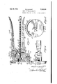
since the same have been found in practice to -Figure l represents a side elevational view,
partly in section, showing a device embodying my invention. l
Figure 2 represents a section generally on line v` 2-2 of Figure 1.
1 0Y Figure 2-a represents: a sectional view on line 'Y 2-a2-a of Figure 1.
Figure`3 represents a section generallyv on line V'3--3 of Figure 1.
Figure 4 represents an end view of the can grip- 15 per and grease expeller with the can removed.
f- Figure 5 represents a perspective view of the can seal.
Figure 6 represents a sectional view of the bottomA of a can of a modified form of construction embodying my invention.
Figure l represents a longitudinal sectional view of a can gripper and eXpeller, and a can held f1 thereby, showing a modified embodiment of my invention.
55'-, Figure 8 represents a plan view of the handle of the ejector shown in Figure 7, with the outer washer partly broken away so as to expose to view the one-way clutch within the handle.
Figure 9 is a plan View of the metal follower plate or piston-like member shown in Figure 7. 5 Figure 10 is a sectional view of a non-metallic packing disc or follower member similar to that shown in Figure 7, but of a somewhat modified construction.
y Figure 11 represents a partially sectioned view 10 of a modied form of device embodying my invention.
Figure l2 represents: a fragmentary sectional View of a construction similar to that shown in Figure 1 in which frictional engagement is pro` 15 vided between the operating lever and the ram rod.
Figure 13 represents a sectional view similar to that shown in Figure 1 of a further modified embodiment of the present invention.
Figure 14 represents a fragmentary side elevational view of the same.
Figure 15 represents a bottom plan View of the same.
According to my invention, I provide an original sheet metal container or can I5 of any suitable cross-section, but preferably of a generally cylindrical formation, as indicated in Figure 1, including the side wall I6, the end member Il permanently fastened thereto by any conventional means, as for instance the turned seam I8, and
' including a bottom end or flange member I9, also permanently fastened thereto by the seam 2B. Merely for convenience in illustration, the seam I8 and the seam 2!) have been shown somewhat 35 enlarged and disproportionate. It will be understood that the wall thickness of both side wall I6 and end members I'I and I9, is less than what is actually shown in the drawings, so that the seams I8 and 29 are correspondingly smaller in actual 40 practice.
The bottom end member is provided with a central opening 2l which is surrounded by an outwardly projecting and more or less cylindrical flange 22. Within the can, a sheet metal sealing member or bottom-forming plug 23 is provided,
toni end member' i3 when the plug 23 is in place, as indicated particularly in Figure l.
When the bottom-forming plug member 23 is thus in place and irictionally gripped within the hanged opening 2l of the bottom of the can, it serves as a removable seal for said bottom opening, but is removable from the flanged opening 2l only in an inward direction indicated by the arrow 29.
Within the can, a follower disc or piston-like member 38 is provided, preferably of sheet metal orthe like, having an annular flange 3i, which is adapted more or less snugly or loosely to fit within the cylindrical wall i6 of the can, sothat any movement of the follower disc or pistonlike member 36 in the direction of the arrow 29 will force the contents of the can also in the direction of the arrow 29 without leaving behind any appreciable amount of the material. The follower disc or piston-like member 30 (in the embodiment of the invention shown in Figure 1) is provided with a socket-like reces-s 32, disposed centrally with respect to the disc, which may have a closed end 33, or which may be open at its inner end, thereby merely leaving an annular inwardly extending flange to surround the inwardly projecting portion 24 of the bottom-forming plug 23. Either the plug 23 per se, or the lpiston 38 and associated plug 23 jointly, may be considered to constitute a bottom portion which coacts with the end portion i9 to form a composite bottom for the container.
The top end member l1 of the container I5 is preferably provided with a screw-threaded neck 34, which may be fastened thereto by any suitable means, as for instance, by soldering at 35, or by other suitable means known in the canmaking art. The screw-neck 34 is adapted to receive a corresponding screw-cap 36 having any suitable sealing gasket 31 therein, for effecting a grease-proof seal.
The can is assembled with the plug 23 in place, as indicated in Figure 1, and with the follower member 38 in its bottom-most position, also indicated generally in Figure 1, and with the screwcap 36 removed. The can is then filled with a predetermined amount of grease, of the particular grade and kind desired, and the screw-cap 36 then applied tightly to the screw-neck 34, thereby to form a grease-proof seal. Thereafter, the sealing member shown in Figure 5, and designated generally by the numeral 38 is superimposed upon the screw-cap with its depending leg portions 33 soldered to the end member I1 as at 48. Because of the slight downwardly depending annular flange 4l, which surrounds the end of the screw-cap 36, and also because of the soldered relationship between the depending leg portions 39 and the lend member l1, the screw-cap 36 cannot be removed without first removing the seal 38. 'I'he seal 35 is removed by breaking the soldered joints 48.
The ejector 42 adapted generally to coact with the container i5, includes a can gripper portion and a ram-rod and actuating means therefor in operative relation to the can gripper portion. Thus, a base plate 43 or an equivalent structure is provided, including the stationary bead-engaging member 44, of more or less arcuate shape and integrally or otherwise xedly related to the base or equivalent structural member 43, and a movable bead-engaging member 45 at a point more or less diametrically opposite to the beadengaging member 44. The movable bead-engaging member 45'may be pivoted at 46 to any suitable webbing or other structural member 41 integrally or otherwise xedly related to the member 43, and yieldably held in an engaging position by any suitable spring 48.
The members 44 and 45 are adapted to engage the slight annular bead-like seam 29 surrounding the bottom end of the can, thereby to hold the can fast and in predetermined relation to the ram-rod 49, which extends through the member 43 at generally a right angle thereto, and
hence, in `generally axial alignment with the can l5. In the embodiment of my invention shown particularly in Figure 1, the ram-rod is provided with a series of spaced annular grooves 58 throughout its length, with the exception of the innermost terminal portion thereof, which is adapted to project into and contact with the plug member 23.
The annular grooves 50 include the more or less vplane annular surfaces 5| vgenerally at a right angle to the rod axis and the inclined and moreor less conical surfaces 52, so as to form in effect, a rack which may be advanced positively by means of the spring-tensioned pawl 53, regardless however, of any rotation of the rod itself. The rod 49 is slidably mounted within a suitable bore 54 of the guide member 55, which is also preferably integrally or otherwise Xedly related to the member 43 which carries the beadengaging members 44 and 45.
A stationary handle 56 is xedly secured to the member 43 by riveting or otherwise fastening it to the web 41, as at points 51. If desired, the handle 56 may be also formed Vintegrally with the web 41 and hence, with the member 43 which carries the bead- engaging members 44 and 45. The handle 56 is preferably of a slightly dished cross-section as indicated in Figure 3, and eX- tends along the ram-rod 49, and tends to protect the same against injury in handling and operation of the ejector.
The movable handle 58 is preferably pivoted to the member 43, as for instance, by means of the pivot 59 extending through said handle 58 and through the pivotal lug or hinge member 60, which is also integrally or otherwise xedly o1' stationarily related to the member 43, and hence, to the bead-engaging members 44 and 45. In suitable spaced relation to the pivot point 59, a hole or other suitable recess 6| vis provided in the han-dle 58, for slidably receiving the pawl 53. The pawl 53 is provided with an extension rod 62, which is preferably screw-threadedly secured thereto, which extends through the handle and terminates in the knob 63. The knob 63 includes a lateral pin or similar lateral projection 64 which slides in suitable slots, and which, when raised clear of said slots and disposed transversely, will keep the pawl 53 in a retracted and inoperative position in relation to the ram rod 49. The spring 65 acts upon the pawl 53 to maintain it in resilient contact with the ram rod 49 when the transverse lug or pin 64 is not so disposed as to keep the pawl in the retracted position.
Any suitable spring, such as the spring 66, tends to displace the handle 58 in the opening direction indicated by the arrow 61.
In the normal use of the device of my present invention, the seal 38 is removed from the can and the screw-cap 36 also removed therefrom, andthe can held in operative position between the bead-engaging members 44 and 45, as shown in Figure 1. Thereupon, the device is gripped in one hand in the manner in which pliers are generally gripped, and the handle 58 pressed towards the handle 56 repeatedly, thereby causing the ram-rod 49 to be Vadvanced in the direction of the arrow 29.' The 'rst advance causes the dislodgment of the plug 23 from its frictional engagement with the flanged opening 2| in the bottom of the can, while a further advancement moves the plug 23 and the piston-like follower member 39 in the direction of the arrow 29, thereby to exp-el the contents of the can. This operation may be continued until the entire contents has been displaced, whereupon the empty can is removed from between the bead-engaging members 44 an-d 45, and is discarded, as it cannot be thereafter re-lled. The insertion and removal of the can is effected by depressing the handle-like portion 68 of the member 45 in the direction of the arrow 69.
If desired, a discharge spout, such as illustrated partticularly in Figure '7, may be screwthreadedly affixed to the screw-threaded neck 34 of the cam i5 during the discharge operation. This spout is particularly desirable where it is desired to expel and dispense the grease into some more or less inaccessible or inconveniently located opening, as for instance, the re-fill opening of the transmission, differential, or free-wheeling units of an automobile.
In Figure 6, I have illustrated a modified form of container construction embodying my invention, wherein the plug and follower piston are made integrally with each other thus jointly constituting a bottom portion cooperating with the end portion I9. Thus, in this modified embodiment of follower piston construction, the plug 23 and piston 30 are formed in continuation of each other.
While in the particular embodiment of my invention shown in Figure 1,' the ram-rod 49 is shown provided with tooth-like recesses, for positive engagement by a pawl, it is to be understood that the engagement between the movable handle and the ram-rod may be of a frictional character, instead of as the positive character shown. Thus, by providing a smooth ram-rod, and surrounding it by a friction gripping member, the aperture of which is slightly greater than the diameter of the rod, the rod may be advanced in the direction of the arrow 29, by causing the handle 58 to push the friction gripping member off-center, in the direction of the arrow 29, thereby cooking or inclining said friction gripping member in relation to the ram-rod, and causing frictional engagement between the two. Any suitable spring may then be provided for returning the friction gripping member to its initial position. By placing the spring more or less coaxially with relation to the aperture in the friction gripping member, the latter may be returned to its original position without any frictional engagement with the ram-rod.
In Figure '7, I have illustrated a modified embodiment of my invention, wherein the ram-rod 79, is provided with a coarse pitch or a multipitch screw 'l I, which is threaded through a correspondingly and internally screw-threaded bushing 12, disposed coaxially with respect to the member 53.
In this embodiment of my invention, the ramrod is advanced by means of a handle 13 which may be fixedly or otherwise secured to the outerv end of the ram-rod 19. In the particular embodiment of the invention shown in Figure 7, the
' handle 13 is so mounted upon the outer end 14 of the ram-rod l0, as to rotate freely with respect to the ram-rod in one direction, and frictionally to grip the ram-rod when rotated in the opposite direction. Thus, to the end 14 of the ram-rod 19, a sleeve-like bushing 'l5- is secured (against rotation) by means of any suitable locking pin 16. The bushing 'l5 is provided with a lateral flange ll. The handle 13 is provided with a central opening 18, of generally the same diameter as the outer diameter of the bushing l5, and immediately adjacent said opening, is also provided with a pair of roller chambers 19, in diametri-1 cally opposite relation to each other. The chambers 19 have outer inclined or eccentric camming surfaces 89. A roller 8| is interposed between the surface and the cylindrical surface of the bushing T5, and is yieldably urged in the direction of the intended rotation of the ram-rod, to wit, in the direction of the arrow 82, by means of the springs 83, acting through suitable roller-engaging blocks 84. The cover plate held in place by the screw 86, serves to hold the handle and rollers in assembled relation to each other, and to the ram-rod. Thus, by rotating the handle in the direction of the arrow 8l, the screw-threaded ram-rod is caused to rotate in a direction which will urge said rod forwardly in the direction ofi the arrow 29. When rotating the handle in the opposite direction (arrow 82) the handle is moved independently of the ram-rod. By this means, the ram-rod may be advanced by'repeated oscillations of the handle, without the necessity of taking a new grip on the handle with each operation.
The contact end of the ram-rod 10, is preferably devoid of the screw-threads 'H and the bushings 12 or equivalent member, is preferably recessed as at 88, for a depth sufficient to receive the thread-free contact end of the ram-rod 18, so that the ram-rod may be retracted completely, or at least to a point where it is fully receded from the plug or follower member. great inclination of the thread 1I, the ram-rod may be moved back to its initial or outer position merely by pushing it through the bushing in a direction opposite to the arrow 29.
Any suitably curved or straight spout 89, of any desired length, may be provided, having a screw-threaded coupling member 99 at one end thereof, adapted threadedly to engage the screwthreaded neck 34 of the can l5. Any suitable sealing gasket or washer 9| may also be provided,
within the coupling member 96 for effecting a seal during the discharging operation. The nozzle or spout 99 may be of any suitable piece of tubing which is extended through a corresponding opening 92 in the coupling member 99 and is soldered" i;
in place as at 93 and 94.
In Figures 7, 9, 10 and 11, I have also illustrated modified forms of follower members or piston members. In one of these modied embodiments of my invention, the metallic follower plate 95 is provided with an aperture 96, preferably slightly flared in the direction of the arrow 29, and adapted snugly to t over the cylindrical portion 24 of the bottom-forming plug 23. If desired,
the follower plate 95 may also be provided with?" the annular flange 3l similar to that indicated in Figures 1 and 6. In this embodiment of the invention however, I may also provide a suitable number of spaced radial flutes in the sheet metal plate 95 thereby to give greater rigidity to the:
plate. The plate is preferably also slightly dished as indicated in Figure 7.
In addition, to the metallic plate 95 or the metallic plate 30 (either one), I may also provide a non-metallic packing disc which may ber Because of thel in the forni of a sheet of cardboard, or may be a cardboard center 98, having a relatively thin and more or less grease-resistant sheets of paper or similar material 99 and Ilm on either side thereo-f. A metallic retainer plate ISI having a central aperture EQ2 fitting snugly over the member 24 of the plug 23, serves to hold the packing disc in assembled relation to the piston-like member 95 (or 3i!) and the plug 23. The non-metallic packing disc, consisting either of the sheet of cardboard 9S, or' a piece of cardboard 98 flanked on either one or both sides by a sheet of more or less firm and more or less grease-resistant 'cheap material such as S9 and Iii, is tted snugly within the cylindrical shell I@ of the can I5, so that more complete removal of the grease is made possible. Thus, by this non-metallic packing disc, a more accurate contact is obtainable between the piston assemblage and the cylindrical wall of the can. In Figure 7, the annular flange 3l of the metallic follower piate 95 is shown slightly spaced from the cylindrical wall of the can. The clearance shown in the drawings is probably excessive and greater than the actualclearance supplied, but it will be understood that this excessive clearance shown in the drawings is merely for purposes oi illustration, that is, to show that the non-metallic packing disc ts the cylindrical wall of the can more snugly and more accurately than the metallic follower plate. In this case, the metallic follower `plate serves more or less asa guiding member.
In Figure l0, a further modified form of construction is shown for the non-metallic packing disc, wherein the leading side of the asernolage is provided with an upwardly flared or flanged portion H33, which, being i'ormed of 4more or less pliable though initially form-retaining material,
' such as a piece of varnished paper, waxed paper,
or otherwise treated paper, or similar fibrous material, serves to effect a more complete seal between piston assemblage and cylinder wall during the expelling operation, and is then crushed flat against the upper terminal member Il of the can when the piston has been forced to the limit. In this manner, a more eflicient sealV is effected during the major portion of the expelling operation, without however, interfering with the limit of movement of the piston. Thus, while the flange i-Il3 formed of paper or other similar material, is sufficiently form-retaining to have the effect of a cup-washer, with the pressure of the contents tending to force it against the cylinder wall, yet it is sufliciently flexible to be crushed and flattened out' against the end of the can Aso that the last bit of grease may also be expelled from the can. l
In Figure 1l, a further modified form of piston unit is shown, in which a cup-shaped paper disc m5 is used alone. in conjunction with a metallic follower plate, such as the follower plate 95 or 3i). Thus, a suitably form-retaining paper or other fibrous material may be provided in a generally cup-shape having the ilange which will be forced against the cylinder wall by any slight grease pressure while the grease is being expelled, and which will at the same time, be flattened out and crushed against the end of the can during the last portion of the stroke of the piston, so
- that the last bit of grease may also be expelled.
While the follower plates Sii and 95 may be slightly dished, as indicated in Figures 7 and 11, the force of the ram-rod will hatten out this slight concavity during the last portion of the stroke, when-the edge of the follower plate is. abutting the end of the can, thereby giving the maximum displacement of grease. Furthermore, virtue of the dished follower plate illustrated in Figure 7, thecombined forward force of the ramrod and the resistive forces exerted by the body of grease will slightly flatten out the slight concavity and thus will slightly increase the diameter of the dished piston and thereby compressively urge the peripheral edge of the packing (which pack-- ing is in substantial edge-wise contact with the cylindrical body wall as distinguished from the side-wise contact which would be present were the packing provided with a cup-washer-orming peripheral flange) into closer edge-wise Contact with the cylindrical body wall.
While in Figures l and 7, the can is shown .Y gripped at its bottom seam 2d, I may also effect an engagement' between the can and the ejecting means at the upper seam IB, as shown particularly in Figure 11.
It should be understood that one of the principal objects of my present invention is to provide means whereby original containers of grease may be emptied directly into the point of ultimate use, by expelling meansr cooperating with the can, and whereby cans of varying length may be used in conjunction with the same expelling member. Thus, it is my plan to provide a series of dierent sized cans, as for instance, a onepound can, two-pound can, three-pound can, et
cetera having the same diameter but varying in.;
length according to the contents or volumetric capacity desired, and to provide expelling means which Will effectively coact with the different lengths of cans, by engaging the bottom or upper seams.
fied embodiment of my invention by which cans of varying lengths (though of the same diameter) may be engaged at their upper seams i8, by means of a plurality of adjustable bead-engaging members IIil, having overhanging clawlike members III, and being slidably mounted within guide members IIB, pivoted at points IIS with suitable lugs lill which are integrally or otherwise i'ixedly related to the base member llt;
The springs 48 tend to deflect the guides I I2 and hence the members I lil in an engaging direction. The members IIB are preferably provided with a series of teeth along their outer or inner surfaces designated generally by the numeral H5, which are adapted to be engagedby the pawl IIS, yieldably pressed into Vcontact therewith by the spring IIT. The pin I i8 extending transversely through the rod-like extension Il!! of the pawl IIi, is adapted to slide invand out in a slot IZB of suicient depth to permit the pawl Il@ to engage the teeth I I5. `A pair of shaliower recesses IZI are also provided at a right angle to the slot IZB, for receiving the pin H8 when it is desired to retain the pawl I I6 in a retracted and inoperative position. This may be effected by pull- I22, and turning the knob L tion, the pawl retains the members H0 in place,v Y and the grease may1 then beY expelled by the operation of the handle 124. The handleY I2@ is similar to the handle 73, except it is provided with an annular rim |25.
..35 Hence, in Figure 11, I have illustrated a modi- It will be understood that the various modifications shown in the various elements of the present invention, can be variously related to each other.V Thus, I may use any one of the forms of piston and follower plate construction shown in these drawings, with any one of the ejecting means. Similarly, for instance, I may use the ratchet type ram-rod 49, or the frictionally engaged ram-rod in place of the screw-threaded ram rod in either one of the embodiments of the invention.
Similarly, while in Figures 1 and 7, I have shown one stationary and one movable beadengaging member (44 and 45), I may provide a plurality of movable bead-engaging members similar to the member 45, in place of the stationary member 44. So too, in the embodiment shown in Figure 1l, I may provide one or more of the guides 2 in fixed relation to the member 43 instead of in pivotal relation thereto.
In the embodiment of my invention shown in Figure 12, the ram rod |26 is surrounded at one point by a friction plate |21 having an aperture |28 therein slightly larger than the diameter of the ram rod |26, and being adapted to be engaged at any suitable point, as for instance, at |29, off-center with respect to the hole |28. by means of the operatng lever 58 which is pivoted at 59 in a manner similar to that shown in Figure 1. The spring |30 tends to return the friction plate |21 to its initial position with frictional engagement between it and the rod |28. 'I'he spring |35 also tends to turn the handle 58 into its open position. While in Figure 12, it is not shown, it is intended to provide a spring similar to the sp-ring 66 in the embodiment shown in Figure l, in order that the handle 58 may be more positively returned to its open or initial position. In other respects, the member 43 is similar to the member 43 shown in Figure 1, except Ythat a deep recess |3| is provided for receiving the free end of the ram rod |26 together with the stop pin |32, so that the ram rod and the stop pin may be completely retracted. In Figure 12, I have also shown the member 43 of. a substantially greater depth or transverse dimension. v
In Figure 13, I have illustrated certain other features of my present-invention, in which the ram rod 49 is engaged by a pivoted pawl |33, carried upon a pivot |34 by the handle 58. The nawl |33 is yieldably urged towards the ram rod 49 by a suitable helical spring |35, while the set screw |36 adjusts the limiting position of the pawl |33 in relation to the handle 58. Thus, when the handle 58 is in the completely retracted position, deiiected in the direction of the arrow 31, the pawl |33 will be clear of the rod 49, so that the rod 49 may be moved backward. The spring |38 serves to open the handle 58. The spring pressed plunger |39, urged by the spring |40, serves yieldably to retain the rod 49 in any position.
It will be understood that I may interchange the alternative features of one form of construction for the corresponding features of. another form of construction shown in these drawings, although I have not in the drawings illustrated all such possible constructions with these elements interchanged.
I am aware that my invention may be embodied in other specific forms without departing from the spirit or essential attributes thereof, and I therefore desire the present embodiments to be considered in all respects as illustrative and not restrictive, reference being had to the appended claims rather than to the foregoing description to indicate the scope of the invention.
Having thus described my invention, what I hereby claim as new and desire to secure by Letters Patent is:
1. Grease dispensing apparatus comprising an original grease container having a generally cylindrical body and having endeopenings at its opposite ends, closure means closing the upper ond-opening, inwardly movable but non-removable closure means associated with the bottom end-opening, said latter closure means including two separate annular portions, one a generally cylindrical flange-like annular portion for frictionally gripping and sealing with the bottom endmopening while the container is in storage or transit and prior to actual use, and the other an annular portion for engagement with the cylindrical side-wall of the container during operative inward movement of said closure means, said latter closure means being adapted to be moved out of sealing relation to the bottom end-opening and to be moved inwardly in operative relation to the side-wall of the container to dispense the grease of the container in the direction of the upper end thereof, and an annular ange member parallel with said first-mentioned annular portion of said inwardly movable closure means, said last-mentioned annular flange member dening said bottom end-opening and being adapted to grip said inwardly movable closure means through mutual engagement of said two parallel and generally cylindrical flanged portions over an annular zone of substantial axial extent.
2. Grease dispensing apparatus comprising an original grease container having a generally cylindrical body and having end-openings at its opposite ends, closure means closing the upper end-opening, inwardly movable but non-removable closure means associated with the bottom end-opening in frictionally gripped and sealed relation while the container is in storage or transit, said latter closure means including two separate annular portions, one for frictional gripping and sealing engagement with the bottom. endopening while the container is in storage or transit and prior to actual use, and the other for engagement with the cylindrical side-wall of the container during operative inward movement of said closure means, said latter closure means being adapted to be moved out of sealed relation to the bottom end-opening and to be moved inwardly in operative relation to the cylindrical side-wall of the container, to displace the grease content of the container in the direction of the upper end-opening, and manuallyoperable ejector means adapted detachably to engage an end of said container and to advance said inwardly movable means in the direction of the upper endopening; said ejector means including means adapted to extend through said bottom endopening of the container.
3. Grease dispensing apparatus including the combination with an original grease package comprising a can having a sheet metal bottom member capable of having a portion thereof moved inwardly, said bottom member being permanently secured to the side-wall of the can by means or an inter-folded and inter-locking peripheral seam at the terminal of the side-wall of the can, said seam projecting laterally to a slight extent at said terminal and constituting a peripheral bead at the bottom end of the can, of ejecting means adapted to cooperate with said can, said ejecting means including a plurality of bead-engaging means movable with relation to each other and adapted detachably to interlock With and engage said peripheral bead of said can, a ram rod carried by said ejecting means and slidably mounted generally at a right angle to the plane of said bead-engaging means, said ram rod being located generally coaxially with respect to the eiective circle of said bead-engaging means, and means for intermittently advancing said ram rod to move inwardly a portion of said bottom member.
4. Grease dispensing apparatus including the combination with an original grease package comprising a can having a sheet metal bottom member capable of having'a portion thereof moved inwardly, said bottom member being permanently secured to theY side wall of theY can by means of an inter-folded and inter-locking peripheral seam at the terminal of the side Wall of the can projecting laterally to a slight extent at said terminal, and constituting a peripheral bead at the bottom end of the can, of ejecting means adapted to cooperate with said can, including a plurality of bead-engaging means movable with relation to each other and adapted detachably to interlock with and engage said yterminal bead of said can, a ram rod carried by said ejecting means and slidably mounted generally at a right angle tothe plane of said bead-engaging means and being located generally coaxially With respect to the effective circle of said bead-engaging means, and means for intermittently `advancing said ram rod, said ram rod advancing means having means whereby it may be free from lthe ram rod independently of said advancing means by longitudinal force exerted directly upon the ram rod, to move inwardly a portion of said bottom member.
5. Grease dispensing apparatus including the combination with an original grease p-ackage comprising a can having aV sheet metal bottom memberV capable of having a portion thereof moved inwardly, said bottom member being permanently secured tothe side-wall of the can byn means of an inter-folded and inter-locking peripheral seam at the terminal of the side-wall of the can, said seam projecting laterally to a slight extent at said terminal and constituting a peripheral bead at the bottom end of the can, of ejecting means adapted to cooperate with said can, said ejecting meansiincluding bead-engaging means adapted detachably to interlock with and engage said peripheral bead of said can, a ram rod carried by said ejecting means and slidably mounted generally at a right angle to the planeY of said bead-engaging meansfsaid ram rod being located generally coaxially with respect to the eiective circle 'of said bead-engaging means, and manually operable means movable in a direction generally transversely of said ram rod for intermittently advancing said ram rod to move inwardly a portion of said bottom member, said manually operable means being adapted for operation by one hand.
6. Grease dispensing apparatus comprising an original grease container having a generally cylindrical body and end-openings at its opposite ends, a movable head portion originally gripped in the bottom end-openingY of said container in sealed relation thereto, said head portion having a central inwardly projecting socket, and means adapted to engage said container independently of the end wall thereof and further adapted to from the container, said means including la ram rod adapted toenter said socket, and means for forcing said ram rod longitudinally of said container to move said head portion inwardly.
7. In greaseY dispensing apparatus, a grease container having a grease expelling piston element originally associated with the bottom thereof, meansfor moving said grease expelling piston, said means comprising in combination a pivoted handle, meansfor attaching said handle to they means whereby said pawl may be disabled by pulling said rod to withdraw said pin from its slot and turning the pin to hold the pawl in withdrawn position.
8. Grease dispensing apparatus comprising an original grease container having a side-wall and having end-walls permanently affixed thereto and having an end lopening in each of its opposite end-walls, means adjacent the 1bottom end-wall v of said container and adapted for lquick detachable and attachable engagement with said container independently of said bottom end-wall, said means including a plunger to expel grease from said container, and a fixed handle and a pivoted handle extending generally parallel to the axis of the container and lying generally within the projected area of the bottom end-wall of the container; the outer end vof said xed handle lying generally adjacent to the axis of the container, extended, to promote grasping of both handles by one hand.
9. Grease dispensing apparatus comprising an original grease container having a'generally cylindrical body, a toppermanently secured to body at one end, an annular peripheral flange secured to the other end of the cylindrical body by means of any suitable annular seam, said annular flange including a short and more or less cylindrical portion, and a bottom disposed within said body and Within said flange portion and having a short generally U-shaped annular reiniorcement including a moreV or less cylindrical portion parallel to said cylindrical portion. of theA aforesaid annular flange and adapted to grip said annular flange through engagement of the two parallel and generally cylindrical portions over an annular'aone of substantial axial extent.`
l0. Grease dispensing apparatus comprising an original grease container having a generally cylindrical body, a top permanently secured to said body at one end, an annular peripheral flange Secured to the other end of the cylindrical body by means of any suitable annular seam, said annular ange including a short and more or less cylindrical portion, a bottom disposed Within said body and within said flange portion and having a short generally U-shaped annular reinforcement including-a more or less cylindrical portion parallel to said cylindrical portion of the aforesaid annular flange and adapted to grip said annular flange through engagement of the two parallel and generally cylindrical portions over an annular zone of substantial axial extent, and
c a packing disc generally adjacent the bottom and disposed inwardly of the same with its periphery in generally sealing contact with said cylindrical body.
l1. Grease dispensing apparatus comprising an original grease container having a'generally cylindrical body, a top permanently secured to said body at one end, an annular peripheral llangc secured to the other end of the cylindrical body ley-means Yor any suitable annular seam, said annular flange including a short and more or less cylindrical portion, a bottom disposed within said body and within said flange portion and having a short generally U-shaped annular reinforcement including a more or less cylindrical portion parallel to said cylindrical portion of the aforesaid annular ange and adapted to grip said annular ilange through engagement of the two parallel and generally cylindrical portions over an annular zone of substantial axial extent, and an expansive packing ring, carried by said bottom, in contact with said cylindrical body.
l2. Grease dispensing apparatus comprising an original grease container having a generally cylindrical body, a bottom portion forming with said body a lapped'seam projecting laterally of the body at the bottom end thereof, a second bottom portion frictionally held in one end of the cylindrical body, a top permanently secured to said bodyat the other end; said second bottom portion being capable ci displacement inwardly ol the body but being incapable ci removal from the body, a discharge opening in said top, readily detachable and attachable claw-like gripping adapted to engage said seam of said-container, a plunger carried by said gripping means in generally axial alignment with said container, and manually operable means for advancing said plunger to displace said second bottom portion towards the opposite end or" the body of the container.
13. Grease dispensing apparatus comprising an original grease container Vhaving a generally cylindrical body, a bottom portion forming with said body a lapped seam projecting laterally of the body at the bottom end thereof, a second bottom portion frictionally held in one end of the cylindrical body, a top permanently secured to Y said body at the other end; said second bottom portion being capable of displacement inwardly of the body but being incapable of removal from the tbody, a packing disc disposed in generally adjacent relation to said second bottom portion, with its periphery contacting the inner cylindrical wall of the body, a discharge opening in said top, readily detachable and attachable claw-like gripping means adapted to engage said seam, a
plunger carried by said gripping means in generally axial alignment with said container, and manually operable means for advancing said plunger to displace said second bottom portion towards the opposite end of the body of the container.
14. Grease dispensing apparatus comprising an original grease container having a generally cylindrical body, a bottom portion forming with Y said body a lapped seam projecting laterally of the body at the bottom end thereof, a second bottom portion rictionally held in one end of the cylindrical body, a top permanently secured to said body at the other end; said second bottom i portion being Vcapable of displacement inwardly of gripping means adapted to engage said seam, a plunger carried by said gripping means in generally axial alignment with said container, and manually operable means for advancing said plunger to displace said second bottom portion towards the opposite end of the body of the container.
15. Grease dispensing apparatus comprising an original grease container having a generally cylindrical body, a top permanently secured to said body at one end, an annular peripheral ilange secured to the other end of the cylindrical body by means of any suitable annular seam, said annular flange including a short and more or less cylindrical portion, a bottom disposed within said body and within said ange portion and having a short generally U-shaped annular reinforcement including a more or less cylindrical portion parallel to said cylindrical portion of the aforesaid annular flange and adapted to grip said annular flange through engagement of the two parallel and generally cylindrical portions over an annular zone of substantial axial extent, readily detachable and attachable claw-like gripping means adapted to engage one end of said container, a plunger carried by said gripping means in generally axial alignment with said container, and manually operable means for advancing said plunger to displace said bottom towards theV opposite end of the body of the container.
16. Grease dispensing apparatus comprising an original grease container having a generally cylindrical body, a top permanently secured to said body at one end, an annular peripheral flange secured to the other end of the cylindrical body by means of any suitable annular seam, said annular flange including a short and more or less cylindrical portion, a bottom disposed within said body and within said ilange portion and having a short generally U -shaped annular reinforcement including a more or less cylindrical portion parallel to said cylindrical portion of the aforesaid annular flange and adapted to grip said annular flange through engagement of the two parallel and generally cylindrical portions over an. annular Zone of substantial axial extent, a packing disc generally adjacent the bottom and disposed in- Wardly of the same with its periphery in generally sealing contact with the cylindrical body, readily detachable and attachable claw-like gripping f' means adapted to engage one end of said container, a plunger carried by said gripping means in generally axial alignment with said container, and manually operable means lor advancing said plunger to displace said bottom towards the opposite end of the body of the container'.
17. Grease dispensing apparatus comprising an original grease container having a generally 'cylindrical body, a. top permanently secured to said body at one end, an annular peripheral flange secured to the other end of the cylindrical body by means of any suitable annular seam, said annular flange including a short and more or less cylin drical portion, a bottom disposed within said body and within said flange portion and having a short generally U-shaped annular reinforcement including a more or less cylindrical portion parallel to said cylindrical portion of the aforesaid annular ange and adapted to grip said annular flange through er ement oi' the two parallel and generally cyllno A tio' ,ver an annular zone of substantial axial extent, an expansive packing ring carried by said bottom and in contact with said cylindrical body, readily detachable and attachable claw-like gripping means adapted to i displace said bottom towards the opposite end of the body of theicontainer. Y Y
18. Grease dispensing apparatus comprising an original grease container having a generally cylindrical body, a top permanently secured to said body at one end, a bottom at the other end of said body, a lapped seam, between said body and said bottom, fcrming an outwardly projecting peripheifal bead' surrounding said last mentioned end of the body, and manually operable means provided with a plurality of claw-like` members for quick detachable and attachable engagement with said bead and having a member adapted to engage and displace said bottom from its initial position inwardly of the body of the container and advance it towards the other end of the container.
19., Grease dispensing apparatus comprising an original grease container having a generally @feylindrical body, a top permanently secured to said body at one end, a bottom at the otherV end of said body, a lapped seam, between said body and said bottom,rforming an outwardly? projecting peripheral bead surrounding said last mentioned end of the body, and an ejector having a relatively fixed portion adapted to engage said bead and a spring pressed portion pivoted on said relatively xed portion and adapted also to engage said bead for quick detachable and attachableengagernent therewith, and manually operable means mounted on said fixed portion and havingl a member adapted to engage and displace said bottom from its initial position inwardlyfof the body of the container and advance it towards the other end of the container.
20. Grease dispensing apparatus comprising a grease reservoir having a generally cylindrical body and having a bottom portion forminggwith said body a lapped seam projecting laterally of the body at the bottom end thereofa seco-nd'bottom portion frictionally secured thereto and capable of being displaced only inwardly of the body from its securedposition, said second bottom portion forming a uid seal therewith when in the secured position suflicient to permit the storage, shipmenuand handling of the reservoir ccntaininggrease without leakage past said seal, and forming a uid seal with the inner surface of the cylindrical body of the reservoir when displaced inwardly from its secured position sufiicient to cause the expulsion of the grease contents of the reservoir as a result of such inward displacement at the bottom, readily detachableand attachable claw-like gripping means engaging said lapped seamVa pressure plunger carried by said gripping means in general axial alignment with said container, and manually operablelmeans movable in a direction generally transversely of said plunger and capable of advancing vsaid plunger axially towards Ythe reservoir, and to dislodge said second bottom portion from its frictionally secured*V position and to advance it through the reservoir towards the opposite end thereof.
nal container for lubricant, and constituting a vendable grease package unit, comprising a generally cylindrical body having at least one terminal member permanently aiiixed thereto at one end thereof, and a recessed piston of generally dished contour slidablydisposed within said cylindrical body at the opposite end thereof, the peripheral extremity of said piston being slightly spaced from the inner wall of said cylindrical body, said piston beingprovided with a flangeless peripherallyprojecting annular ringof any suitable nonmetallic packing material insubstantial edgewise contact with said inner wall,and said piston being adapted to receive the thrust of external piston-.advancing means in the recess thereof, whereby the forward thrust of said external piston-advancing means combined with the opposed resistive forces exerted by a body of grease: will tend to slightly increase the diarrieter of said dished piston thereby to directly compress the annular ring of packing material and urge it into closer edgewise contact with the inner wall of said cylindrical body.
22. Grease dispensing apparatus comprising an original grease container having a generally cylindrical bdy, a top permanently secured to said body at one end, an apertured bottom permanently secured to the 'other end of said cylindrical body by means of any suitable annular seam, an inwardly removable bottong closure? member of a diameter substantially smaller than the overall diameter of said aprertured bottom frictionally retained within saidV aperture, readilyv attachable and detachable claw-like gripping means adapted to engage'jsaid annular seam, a 'plunger carried said gripping means in generally axial Qalignment with said container and said closure'memberg, and operable means for advancing said l plunger to displace said inwardly removable bottom closure member towards the top of vsaid container. f Y Y 23. Grease dispensing apparatus comprising a said body a lapped seam projecting laterally of tne body at the bottom end thereof, a second bottom portion frictionally secured thereto and capable of being displaced only inwardly of the body from its secured position, said second bottom portion forming a fliiid seal therewith when in the secured position sufficient to permit the storage,V shipment, and handling of the reservoir containing grease without leakage past saidjY seal, and forming a fluid seal with the inner sur-ir face of the cylindrical body of the reservoir whenV displaced inwardly from its secured position suicient to cause the expulsion ofthe grease contents of the reservoir as a resultY of such inward displacement at the bottom, readily detachable and attachable gripping means engaging said lapped seam, a jpressure plunger carried by said gripping means :in general axial alignment with.Y Said container, and manually operable means Vmovable in a direction generally transversely oi i; said plunger and capable of advancing said *plunger axially towards the reservoir; and toV dislodge said second bottom portion from its frictionally secured position and to advance it through the reservoir towards the opposite end thereof.V Y
24. Grease dispensing apparatus including the combination with an original grease package comprising a can having a sheet metal bottom Y member capable of having a portion thereof 21. In lubricant dispensing apparatus, an origig moved inwardly, said bottom member being permanently secured to the side-wall of the can by means of an inter-folded and interlocking peripheral seam at the terminal of the side-wall of the can, said seam projecting laterally to a slight extent at said terminal and constituting a peripheral bead at the bottom end of the can, of ejecting means adapted to cooperate with said can, in-
cluding a plurality of bead-engaging means movable with relation to each other and adapted detachably to interlock with and engage said peripheral bead of said can, a ram rod carried by said ejecting means and slidably mounted generally at a right angle to the plane of said beadengaging means, said ram rod being located generally coaxially with respect to the eifective circle of said bead-engaging means, and means for intermittently advancing said ram rod to move inwardly a portion of said bottom member, said ram rod advancing means having means whereby it may be freed from the ram rod thereby to permit the retraction of said ram rod independently of said advancing means by longitudinal force exerted directly upon the ram rod.
ROBERT M. BAGLEY.'
Priority Applications (1)
| Application Number | Priority Date | Filing Date | Title |
|---|---|---|---|
| US705562A US2125258A (en) | 1934-01-06 | 1934-01-06 | Grease dispensing apparatus |
Applications Claiming Priority (1)
| Application Number | Priority Date | Filing Date | Title |
|---|---|---|---|
| US705562A US2125258A (en) | 1934-01-06 | 1934-01-06 | Grease dispensing apparatus |
Publications (1)
| Publication Number | Publication Date |
|---|---|
| US2125258A true US2125258A (en) | 1938-07-26 |
Family
ID=24834016
Family Applications (1)
| Application Number | Title | Priority Date | Filing Date |
|---|---|---|---|
| US705562A Expired - Lifetime US2125258A (en) | 1934-01-06 | 1934-01-06 | Grease dispensing apparatus |
Country Status (1)
| Country | Link |
|---|---|
| US (1) | US2125258A (en) |
Cited By (4)
| Publication number | Priority date | Publication date | Assignee | Title |
|---|---|---|---|---|
| US2670881A (en) * | 1951-07-10 | 1954-03-02 | Sawa Fabriks Aktiebolag | Dispensing device for dispensing batter and the like |
| US3289891A (en) * | 1962-11-06 | 1966-12-06 | Continental Can Co | Food containers for manned space ships |
| US3785533A (en) * | 1970-04-29 | 1974-01-15 | Becton Dickinson Co | Coombs serum cartridge with indexing means |
| EP2540659A3 (en) * | 2006-12-22 | 2013-09-04 | Asept International Ab | Device for discharge or outfeed and discharge means for such device |
-
1934
- 1934-01-06 US US705562A patent/US2125258A/en not_active Expired - Lifetime
Cited By (4)
| Publication number | Priority date | Publication date | Assignee | Title |
|---|---|---|---|---|
| US2670881A (en) * | 1951-07-10 | 1954-03-02 | Sawa Fabriks Aktiebolag | Dispensing device for dispensing batter and the like |
| US3289891A (en) * | 1962-11-06 | 1966-12-06 | Continental Can Co | Food containers for manned space ships |
| US3785533A (en) * | 1970-04-29 | 1974-01-15 | Becton Dickinson Co | Coombs serum cartridge with indexing means |
| EP2540659A3 (en) * | 2006-12-22 | 2013-09-04 | Asept International Ab | Device for discharge or outfeed and discharge means for such device |
Similar Documents
| Publication | Publication Date | Title |
|---|---|---|
| US2115591A (en) | Gun for discharging plastic compositions | |
| US3268123A (en) | Dispensers for fluent masses | |
| US2745575A (en) | Printing ink holder and dispenser, including a cylindrical container and piston | |
| US3540448A (en) | Rechargeable applicator for dispensing substances in a foam condition | |
| US2981449A (en) | Caulking compound cartridge with improved spout | |
| US3169690A (en) | Container | |
| US2728494A (en) | Containers for pasty and similar substances | |
| US2661126A (en) | Dispensing container having a slidable bottom forming a follower | |
| US2587683A (en) | Disposable caulking gun | |
| US2393217A (en) | Grease container | |
| US2485467A (en) | Dispenser with screw actuated follower | |
| US3130872A (en) | Device for discharging viscous fluid | |
| US2205604A (en) | Dispensing apparatus for plastic material | |
| US2125258A (en) | Grease dispensing apparatus | |
| US2037989A (en) | Cartridge | |
| US3917124A (en) | Follow plate for dispensing material | |
| US1782526A (en) | Tubular container | |
| US3094256A (en) | Dispensing cap for squeeze-type containers | |
| US2125259A (en) | Grease dispensing means | |
| US2493891A (en) | Grease gun cartridge | |
| US2234857A (en) | Dispensing container | |
| US3375056A (en) | Liquid soap dispenser having integral self-sealing dispensing means | |
| US3464592A (en) | Roll-ball dispenser for paste products | |
| US3790038A (en) | Follow plate for dispensing material | |
| US3305143A (en) | Container for use in manned space ships |