US2119082A - Locomotive structure - Google Patents
Locomotive structure Download PDFInfo
- Publication number
- US2119082A US2119082A US42343A US4234335A US2119082A US 2119082 A US2119082 A US 2119082A US 42343 A US42343 A US 42343A US 4234335 A US4234335 A US 4234335A US 2119082 A US2119082 A US 2119082A
- Authority
- US
- United States
- Prior art keywords
- air
- scoop
- locomotive
- smoke
- channel
- Prior art date
- Legal status (The legal status is an assumption and is not a legal conclusion. Google has not performed a legal analysis and makes no representation as to the accuracy of the status listed.)
- Expired - Lifetime
Links
Images


Classifications
-
- B—PERFORMING OPERATIONS; TRANSPORTING
- B61—RAILWAYS
- B61C—LOCOMOTIVES; MOTOR RAILCARS
- B61C1/00—Steam locomotives or railcars
- B61C1/06—Streamlining
Definitions
- This invention relates to a smoke lifting scoop for steam locomotives and particularly for steam locomotives of streamlined type.
- a streamline construction for locomotives including a cowling and hood about the body and forward portions of the boiler.
- This cowling is provided with an air scoop channel or chute opening at its forward end through its front or through the top of the hood and extending rearwardly about and beyond a streamlined smoke stack and terminating'at its rear end adjacent to the stack in a deflector or scoop plate, the construction being such that in the forward travel of the locomotive air flowing rearwardly through the air scoop channel or chute and striking the deflector or scoop plate is deflected upwardly and rearwardly, whereby the smoke and gases issuing from the stack are carried upwardly to a predetermined height and caused to travel rearwardly above the horizontal plane of the top of the locomotive cab, thus preventing the smoke from the stack from clouding the vision of the engineer and also preventing the other smoke nuisances occurring in the operation of an ordinary steam locomotive not so equipped.
- side scoops or chutes independent of the cowl scoop or chute for projecting streams
- the object of the present invention is to further improve and increase the efficiency of the cowl scoop and to provide means for directly supplying thereto auxiliary blasts of air whereby the smoke lifting action of the cowl scoop may be increased according to requirements without the necessity of undesirably changing the form or structure of the cowl scoop.
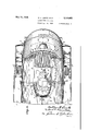
- Fig. l is a View in side elevation of a streamlined locomotive embodying our invention.
- Fig. 2 is a front perspective view thereof.
- Fig. 3 is a top plan view, on an enlarged scale, of the forward portion of the locomotive, with parts appearing in section, showing the smoke stack, cowl scoop and the auxiliary air blast 3 channels or ducts associated therewith.
- Fig. 4 is a side elevation, partly in section, of the parts appearing in Fig. 3.
- Fig.5 is a longitudinal section taken on line 55-of Fig. 3.
- Fig. 6 is a transverse section taken on line 66 5 of Fig. 3.
- l designates a steam locomotive having a boiler 2, cab 3, side running boards 4, and suitably streamlined smoke stack' 5 and auxiliary steam exhaust 6.
- a sheet steel streamline cover comprising a cowling 1 and a hood 8.
- the cowling l extends transversely over the boiler in spaced relation thereto between-the running boards and is supported by a suitable framework structure secured to the boiler'shell and to the running boards.
- the hood 8 extends vertically at an upward and rearward slope from the tip of the pilot to the-forward end of the firebox portion of the boiler, where it is joined to the front of the'cowling, and said hood is parabolically curved transverselyto deflect head or angle wind currents toward the sides of the locomotive. 8a are stairways -or ladders and air chutes at opposite sides of the locomotive. The construction of these parts and their operating characteristics may accord with the disclosure in these respects set forth in the aforesaid prior application.
- the smoke stack and auxiliary steam exhaust are of streamline contour or provided with a suitable streamline fairing or jacket 9, and these elementsare arranged in a-depressed portion at the forward end of the cowling.
- This depressed portion is formed by vertical longitudinal walls ill and an upwardly and rearwardlyinclined rear end wall ll, forming an air channel or-chute l2 extending from the front of the cowling about and on opposite sides of the smoke stack to a point adjacent to and in rear thereof and terminating at its rear end in the wall I I.
- This chute communicates at its forward end with an inlet opening l3 formed partially in the forward portion of the cowling and partially in the central portion of the top of the hood, which opening may be covered by a grille or screen l4 connecting the side walls of the opening and preserving the contour of such portion of the hood.
- the wall ll slopes at a proper angle to form a scoop plate or deflector to deflect currents of air upwardly and rearwardly.
- the present invention provides means for producing and projecting auxiliary currents or blasts of air into the channel or chute to mingle with and augment the volume and increase the smoke lifting effect of the main blast or current of air on the smoke and gases issuing from the smoke stack.
- auxiliary channels or ducts I 5 are disposed on opposite sides of the channel and communicate at their forward ends with air inlet openings l6 provided in the hood on opposite sides of the inlet l3, which openings are covered by grilles or screens I! maintaining the streamline continuity of the sides of the top portion of the hood.
- Each duct I5 is in communication at its rear end with the rear end of the channel or chute I2 through ports or nozzle openings l8, each provided with a louvre or deflector plate IQ for guiding the streams of air issuing from the ducts l5 toward the scoop plate H.
- Air entering each duct [5 through its inlet Hi thus discharges through the nozzles l8 in the form of blasts of high intensity which mingle with the streams of air traversing the channel l2 and striking the scoop plate I I.
- the air blast supplied by the channel I2 is thus augmented in volume and intensity by the auxiliary air blasts from the ducts l5, insuring the lifting of the smoke and gases issuing from the smoke stack to the intended high dissipation level at all locomotive speeds and even when the locomotive is traveling at comparatively low speed.
- This lifting action of the air blasts also promotes the efficiency of the draft through the smoke stack, as will be readily understood.
- the rear end of the ducts l5 may, as shown, be connected in rear of the scoop plate II by a cross duct 20, and the top walls of the ducts l5 and 20 may be provided with vent apertures or slots 2
- auxiliary streams of high velocity are furnished to increase the smoke lifting capacity to a degree to ensure lifting of the smoke at any train hauling locomotive speed and under all contrary natural wind conditions to a level above that of the locomotive cab and cars of the train to prevent the smoke nuisances to which the engineer in the cab and passengers in the cars of the train are ordinarily subjected.
- a locomotive having a boiler, a cab, a smoke stack located forwardly of the cab, an air scoop disposed adjacent to the stack and at least partially surrounding the stack and having an inclined rear surface for directing a current of air upwardly to lift the smoke and gases issuing from the stack to a level above the level of the cab, a central longitudinal air conducting channel extending forwardly from said scoop and communicating at its rear end therewith, a central air inlet at the front of the locomotive communicating with the air conducting channel, air inlets at the front of the locomotive located one on each side of said central air inlet, and air conducting ducts extending longitudinally of the locomotive adjacent to and on opposite sides of and substantially in the same horizontal plane as and substantially parallel with the longitudinal axis of the central channel and having inlet ends communicating with said side air inlets and outlet ends communicating with opposite sides of the scoop for discharging air into the scoop to augment the smoke lifting capacity of the firstnamed current of air.
- a locomotive having a boiler, a cab, a smoke stack located forwardly of the cab, an air scoop disposed adjacent to the stack and at least partially surrounding the stack and having an inclined rear surface for directing a current of air upwardly to lift the smoke and gases issuing from the stack to a level above the level of the cab, an air channel leading forwardly from the scoop in the central line of the locomotive and communicating at its rear end with the scoop, a central air inlet at the front of the locomotive communicating with the forward end of the channel, air inlets at the front of the locomotive located ad- J'acent to and one on each side of the central horizontal air inlet, and air conducting ducts leading from the forward portion of the locomotive on opposite sides of and substantially in the same horizontal plane as and parallel with the longitudinal axis of the channel and having inlet ends communicating with said side air inlets and outlet ends each provided with a longitudinal series of lateral ducts communicating with the adjacent sides of the scoop for discharging air into the scoop at the rear thereof to augment the smoke lifting capacity of the first-name
- a locomotive having a boiler, a cab, a smoke stack located forwardly of the cab, a hood covering the front of the boiler, a streamline cowling extending over the top and downwardly at the sides of the boiler and structurally formed to provide an air scoop disposed adjacent to and at least partially surrounding the stack and opening at its rear end to the atmosphere and having an inclined rear surface for directing a current of air upwardly to lift the smoke and gases issuing from the stack to a level above the level of the cab, an enclosed air conducting channel extending from said scoop a portion of the distance between the same and the hood, an air inlet at the front of the locomotive opening partially through the top of the cowling and partially through the upper portion of the hood and communicating at its rear with the scoop, and air conducting ducts extending longitudinally of the boiler beneath the cowling on opposite sides of and parallel with the longitudinal axis of the air conducting channel for conducting confined currents of air to the scoop, said ducts having inlet ends opening through the upper end of the hood at opposite sides of the air in
- a locomotive having a boiler, a cab, a smoke stack located forwardly of the cab, a hood covering the front end of the boiler, a streamline cowling extending along the top and downwardly at the sides of the boiler between the cab and hood and structurally formed to provide an air scoop comprising a central longitudinal conducting channel disposed at its rear end about the smoke stack and extending therefrom toward the hood, said channel terminating at its rear end in an inclined deflector operating for directing the current of air flowing rearwardly in the channel upwardly to lift the smoke and gases issuing from the smoke stack to a level above the level of the cab, a central air inlet at the front of the locomotive opening through the hood and communicating with the forward end of said channel, an air inlet in the hood on each side of said central air inlet, and air ducts extending horizontally beneath the cowling adjacent to and substantially in the same horizontal plane as and parallel with and at opposite sides of said central channel and having entrance ends communicating at the forward end of the locomotive with said side air inlets and having discharge
- a locomotive having a boiler, a cab, a smoke stack, a hood covering the front end of the boiler, a streamline cowling extending along the top and downwardly at the sides of the boiler and structurally formed to provide an air scoop at least partially surrounding the stack and including an inclined rear surface for directing a current of air upwardly to lift the smoke and gases issuing from the stack .to a level above the level of the cab, an air channel extending beneath the cowling and extending forwardly from the scoop in the central longitudinal line of the locomotive, a central air inlet opening through the hood and communicating with the forward end of the channel for admitting air thereto, air inlets in the hood disposed one on each side of said central air inlet, and horizontal conductors of uniform width extending from the hood beneath the cowling to the rear portion of the scoop adjacent to and on opposite sides of and substantially in the same horizontal plane as and parallel with the longitudinal axis of said channel and communicating at their forward ends with the side inlets in the hood and at their rear ends at a plurality of
Landscapes
- Engineering & Computer Science (AREA)
- Transportation (AREA)
- Mechanical Engineering (AREA)
- Separating Particles In Gases By Inertia (AREA)
Description
y 1938- w. L LENTZ in AL 2,119,082
LOCOMOTIVE STRUCTURE Filed Sept 26, 1935 3 Sheets-Sheet l May 31, 1938.
w. L. LE NTZ ET AL. LOCOMOTIVE STRUCTURE Filed Sept. 26. 1955 s sn ets-shet 2 May 31, 1938- w. LVENTZ ET-AL LO COMOTIVE STRUCTURE Filed Sept; 26, 1935 3 Sheets-Sheet 3 Patented May 31, 1938 UNITED STATES PATENT OFFIQE Kantola, Ashtabula,
Ohio, assignors to The New York Central Railroad Company, a corporation of New York Application September 26, 1935, Serial No. 42,343
Claims.
This invention relates to a smoke lifting scoop for steam locomotives and particularly for steam locomotives of streamlined type.
In a prior application for patent Serial No.
5 42,342, filed September 26, 1935, there is disclosed a streamline construction for locomotives including a cowling and hood about the body and forward portions of the boiler. This cowling is provided with an air scoop channel or chute opening at its forward end through its front or through the top of the hood and extending rearwardly about and beyond a streamlined smoke stack and terminating'at its rear end adjacent to the stack in a deflector or scoop plate, the construction being such that in the forward travel of the locomotive air flowing rearwardly through the air scoop channel or chute and striking the deflector or scoop plate is deflected upwardly and rearwardly, whereby the smoke and gases issuing from the stack are carried upwardly to a predetermined height and caused to travel rearwardly above the horizontal plane of the top of the locomotive cab, thus preventing the smoke from the stack from clouding the vision of the engineer and also preventing the other smoke nuisances occurring in the operation of an ordinary steam locomotive not so equipped. In such prior application is also shown the use of side scoops or chutes independent of the cowl scoop or chute for projecting streams of air upwardly and rearwardly into the atmosphere to augment the smoke lifting action of the lifting streams produced by the cowl scoop.
The object of the present invention is to further improve and increase the efficiency of the cowl scoop and to provide means for directly supplying thereto auxiliary blasts of air whereby the smoke lifting action of the cowl scoop may be increased according to requirements without the necessity of undesirably changing the form or structure of the cowl scoop.
The invention consists of the features of construction, combination and arrangement of parts, F hereinafter fully described. and claimed, reference being had to the accompanying drawings, in
which: 7
Fig. l is a View in side elevation of a streamlined locomotive embodying our invention.
Fig. 2 is a front perspective view thereof.
Fig. 3 is a top plan view, on an enlarged scale, of the forward portion of the locomotive, with parts appearing in section, showing the smoke stack, cowl scoop and the auxiliary air blast 3 channels or ducts associated therewith.
Fig. 4 is a side elevation, partly in section, of the parts appearing in Fig. 3.
Fig.5 is a longitudinal section taken on line 55-of Fig. 3.
Fig. 6 is a transverse section taken on line 66 5 of Fig. 3.
Referring now moreparticularly to the drawings, l designates a steam locomotive having a boiler 2, cab 3, side running boards 4, and suitably streamlined smoke stack' 5 and auxiliary steam exhaust 6. Enclosing the boiler 2 longitudinally between the front of the cab and tip of the pilot is a sheet steel streamline cover comprising a cowling 1 and a hood 8. The cowling l extends transversely over the boiler in spaced relation thereto between-the running boards and is supported by a suitable framework structure secured to the boiler'shell and to the running boards. The hood 8 extends vertically at an upward and rearward slope from the tip of the pilot to the-forward end of the firebox portion of the boiler, where it is joined to the front of the'cowling, and said hood is parabolically curved transverselyto deflect head or angle wind currents toward the sides of the locomotive. 8a are stairways -or ladders and air chutes at opposite sides of the locomotive. The construction of these parts and their operating characteristics may accord with the disclosure in these respects set forth in the aforesaid prior application.
The smoke stack and auxiliary steam exhaust are of streamline contour or provided with a suitable streamline fairing or jacket 9, and these elementsare arranged in a-depressed portion at the forward end of the cowling. This depressed portion is formed by vertical longitudinal walls ill and an upwardly and rearwardlyinclined rear end wall ll, forming an air channel or-chute l2 extending from the front of the cowling about and on opposite sides of the smoke stack to a point adjacent to and in rear thereof and terminating at its rear end in the wall I I. This chute communicates at its forward end with an inlet opening l3 formed partially in the forward portion of the cowling and partially in the central portion of the top of the hood, which opening may be covered by a grille or screen l4 connecting the side walls of the opening and preserving the contour of such portion of the hood. The wall ll slopes at a proper angle to form a scoop plate or deflector to deflect currents of air upwardly and rearwardly. In the forward travel of the locomotive air entering the chute through the inlet opening l3 travels rearwardly therein on opposite sides of and beyond the smokerstack and auxiliary steam exhaust and strikes against the scoop l I, whereby this air and the streams of air flowing along the sides of the smoke stack are shot upwardly and rearwardly to a level above the top of the locomotive cab, carrying with them the smoke and gases issuing from the smoke stack. The top of the forward portion of the channel or chute and the divisions of this channel on opposite sides of the smoke stack may be left open, or may be closed by a cover plate between the hood and a point coinciding with the transverse center of the smoke stack. if desired.
The present invention provides means for producing and projecting auxiliary currents or blasts of air into the channel or chute to mingle with and augment the volume and increase the smoke lifting effect of the main blast or current of air on the smoke and gases issuing from the smoke stack. To this end auxiliary channels or ducts I 5 are disposed on opposite sides of the channel and communicate at their forward ends with air inlet openings l6 provided in the hood on opposite sides of the inlet l3, which openings are covered by grilles or screens I! maintaining the streamline continuity of the sides of the top portion of the hood. Each duct I5 is in communication at its rear end with the rear end of the channel or chute I2 through ports or nozzle openings l8, each provided with a louvre or deflector plate IQ for guiding the streams of air issuing from the ducts l5 toward the scoop plate H. Air entering each duct [5 through its inlet Hi thus discharges through the nozzles l8 in the form of blasts of high intensity which mingle with the streams of air traversing the channel l2 and striking the scoop plate I I. The air blast supplied by the channel I2 is thus augmented in volume and intensity by the auxiliary air blasts from the ducts l5, insuring the lifting of the smoke and gases issuing from the smoke stack to the intended high dissipation level at all locomotive speeds and even when the locomotive is traveling at comparatively low speed. This lifting action of the air blasts also promotes the efficiency of the draft through the smoke stack, as will be readily understood. The rear end of the ducts l5 may, as shown, be connected in rear of the scoop plate II by a cross duct 20, and the top walls of the ducts l5 and 20 may be provided with vent apertures or slots 2| to allow any air in excess of that which may freely pass through the nozzles 8 to escape to the free atmosphere, thus preventing any possible choking of the air at the rear ends of the ducts [5. By thus providing the channels !5 to supply additional streams of air and confining the air until it discharges through the nozzles H! for impingement with the air stream flowing through the channel l2 against the scoop plate II auxiliary streams of high velocity are furnished to increase the smoke lifting capacity to a degree to ensure lifting of the smoke at any train hauling locomotive speed and under all contrary natural wind conditions to a level above that of the locomotive cab and cars of the train to prevent the smoke nuisances to which the engineer in the cab and passengers in the cars of the train are ordinarily subjected.
i i/bile the structural organization shown for the purpose set forth is preferred, it will, of course, be understood that the same is merely exemplificative, and that changes in the form, proportions and arrangement of the parts may be made within the scope of the appended claims without departing from the spirit or sacrificing any of the advantages of the invention.
What is claimed is:-
1. A locomotive having a boiler, a cab, a smoke stack located forwardly of the cab, an air scoop disposed adjacent to the stack and at least partially surrounding the stack and having an inclined rear surface for directing a current of air upwardly to lift the smoke and gases issuing from the stack to a level above the level of the cab, a central longitudinal air conducting channel extending forwardly from said scoop and communicating at its rear end therewith, a central air inlet at the front of the locomotive communicating with the air conducting channel, air inlets at the front of the locomotive located one on each side of said central air inlet, and air conducting ducts extending longitudinally of the locomotive adjacent to and on opposite sides of and substantially in the same horizontal plane as and substantially parallel with the longitudinal axis of the central channel and having inlet ends communicating with said side air inlets and outlet ends communicating with opposite sides of the scoop for discharging air into the scoop to augment the smoke lifting capacity of the firstnamed current of air.
2. A locomotive having a boiler, a cab, a smoke stack located forwardly of the cab, an air scoop disposed adjacent to the stack and at least partially surrounding the stack and having an inclined rear surface for directing a current of air upwardly to lift the smoke and gases issuing from the stack to a level above the level of the cab, an air channel leading forwardly from the scoop in the central line of the locomotive and communicating at its rear end with the scoop, a central air inlet at the front of the locomotive communicating with the forward end of the channel, air inlets at the front of the locomotive located ad- J'acent to and one on each side of the central horizontal air inlet, and air conducting ducts leading from the forward portion of the locomotive on opposite sides of and substantially in the same horizontal plane as and parallel with the longitudinal axis of the channel and having inlet ends communicating with said side air inlets and outlet ends each provided with a longitudinal series of lateral ducts communicating with the adjacent sides of the scoop for discharging air into the scoop at the rear thereof to augment the smoke lifting capacity of the first-named current of air.
3. A locomotive having a boiler, a cab, a smoke stack located forwardly of the cab, a hood covering the front of the boiler, a streamline cowling extending over the top and downwardly at the sides of the boiler and structurally formed to provide an air scoop disposed adjacent to and at least partially surrounding the stack and opening at its rear end to the atmosphere and having an inclined rear surface for directing a current of air upwardly to lift the smoke and gases issuing from the stack to a level above the level of the cab, an enclosed air conducting channel extending from said scoop a portion of the distance between the same and the hood, an air inlet at the front of the locomotive opening partially through the top of the cowling and partially through the upper portion of the hood and communicating at its rear with the scoop, and air conducting ducts extending longitudinally of the boiler beneath the cowling on opposite sides of and parallel with the longitudinal axis of the air conducting channel for conducting confined currents of air to the scoop, said ducts having inlet ends opening through the upper end of the hood at opposite sides of the air inlet of the channel being in communication at their rear ends with the scoop and with the atmosphere and in communication with each other at the rear of the scoop by means of a cross duct in communication with the atmosphere.
4. A locomotive having a boiler, a cab, a smoke stack located forwardly of the cab, a hood covering the front end of the boiler, a streamline cowling extending along the top and downwardly at the sides of the boiler between the cab and hood and structurally formed to provide an air scoop comprising a central longitudinal conducting channel disposed at its rear end about the smoke stack and extending therefrom toward the hood, said channel terminating at its rear end in an inclined deflector operating for directing the current of air flowing rearwardly in the channel upwardly to lift the smoke and gases issuing from the smoke stack to a level above the level of the cab, a central air inlet at the front of the locomotive opening through the hood and communicating with the forward end of said channel, an air inlet in the hood on each side of said central air inlet, and air ducts extending horizontally beneath the cowling adjacent to and substantially in the same horizontal plane as and parallel with and at opposite sides of said central channel and having entrance ends communicating at the forward end of the locomotive with said side air inlets and having discharge ends communicating with the adjacent sides of the central longitudinal channel adjacent to the deflector for discharging auxiliary lifting currents of air thereinto.
5. A locomotive having a boiler, a cab, a smoke stack, a hood covering the front end of the boiler, a streamline cowling extending along the top and downwardly at the sides of the boiler and structurally formed to provide an air scoop at least partially surrounding the stack and including an inclined rear surface for directing a current of air upwardly to lift the smoke and gases issuing from the stack .to a level above the level of the cab, an air channel extending beneath the cowling and extending forwardly from the scoop in the central longitudinal line of the locomotive, a central air inlet opening through the hood and communicating with the forward end of the channel for admitting air thereto, air inlets in the hood disposed one on each side of said central air inlet, and horizontal conductors of uniform width extending from the hood beneath the cowling to the rear portion of the scoop adjacent to and on opposite sides of and substantially in the same horizontal plane as and parallel with the longitudinal axis of said channel and communicating at their forward ends with the side inlets in the hood and at their rear ends at a plurality of longitudinally spaced points with the sides of the scoop, said conductors serving for conducting confined currents of air to the scoop to augment the smoke lifting capacity of the first-named current of air.
CARL F. KANTOLA. WILLIAM L. LENTZ.
Priority Applications (1)
| Application Number | Priority Date | Filing Date | Title |
|---|---|---|---|
| US42343A US2119082A (en) | 1935-09-26 | 1935-09-26 | Locomotive structure |
Applications Claiming Priority (1)
| Application Number | Priority Date | Filing Date | Title |
|---|---|---|---|
| US42343A US2119082A (en) | 1935-09-26 | 1935-09-26 | Locomotive structure |
Publications (1)
| Publication Number | Publication Date |
|---|---|
| US2119082A true US2119082A (en) | 1938-05-31 |
Family
ID=21921362
Family Applications (1)
| Application Number | Title | Priority Date | Filing Date |
|---|---|---|---|
| US42343A Expired - Lifetime US2119082A (en) | 1935-09-26 | 1935-09-26 | Locomotive structure |
Country Status (1)
| Country | Link |
|---|---|
| US (1) | US2119082A (en) |
-
1935
- 1935-09-26 US US42343A patent/US2119082A/en not_active Expired - Lifetime
Similar Documents
| Publication | Publication Date | Title |
|---|---|---|
| US2242494A (en) | Ventilating and cooling system for motor vehicles | |
| US3982600A (en) | Vehicle engine hood | |
| US5407245A (en) | Process and device for reducing the drag in the rear region of a vehicle, for example, a road or rail vehicle or the like | |
| CN110070850B (en) | Streamline flow-through type obstacle deflector and application thereof | |
| US11021174B2 (en) | Rail vehicle having a covered bogie | |
| GB1172442A (en) | Improvements in or relating to a Lift System for Aircraft | |
| CN109421759B (en) | Power car for high speed trains with internal overpressure | |
| US2119082A (en) | Locomotive structure | |
| US2208075A (en) | Railway car | |
| US20160159373A1 (en) | Cooling aeraulics device for a rail vehicle element and corresponding rail vehicle | |
| US2101619A (en) | Locomotive structure | |
| US2223378A (en) | Deflector for windshields | |
| US3586266A (en) | Jet propelled aircraft with auxiliary lifting means | |
| CN210062982U (en) | Vehicle air supply and return structure and railway vehicle with same | |
| US1621356A (en) | Dust-preventing device for rear platforms of vehicles | |
| US2367276A (en) | Air conditioning system for passenger vehicles | |
| US2476368A (en) | Deflecting separator air scoop for ventilating closed vehicles | |
| US2183913A (en) | Locomotive | |
| US3330505A (en) | Thrust reversal and aerodynamic brake for aircraft | |
| US2194929A (en) | Locomotive | |
| CN115626186A (en) | High-speed train pilot | |
| US1950743A (en) | Locomotive | |
| CN115565511A (en) | A high-speed train aerodynamic noise jet noise reduction system | |
| US2272626A (en) | Cooling arrangement for aircraft engines | |
| US2255494A (en) | Railway vehicle structure |