US2106295A - Evaporator - Google Patents
Evaporator Download PDFInfo
- Publication number
- US2106295A US2106295A US26409A US2640935A US2106295A US 2106295 A US2106295 A US 2106295A US 26409 A US26409 A US 26409A US 2640935 A US2640935 A US 2640935A US 2106295 A US2106295 A US 2106295A
- Authority
- US
- United States
- Prior art keywords
- tank
- evaporator
- pump
- fluid
- chamber
- Prior art date
- Legal status (The legal status is an assumption and is not a legal conclusion. Google has not performed a legal analysis and makes no representation as to the accuracy of the status listed.)
- Expired - Lifetime
Links
Images
Classifications
-
- B—PERFORMING OPERATIONS; TRANSPORTING
- B01—PHYSICAL OR CHEMICAL PROCESSES OR APPARATUS IN GENERAL
- B01D—SEPARATION
- B01D1/00—Evaporating
- B01D1/06—Evaporators with vertical tubes
- B01D1/12—Evaporators with vertical tubes and forced circulation
Definitions
- This invention relates .to improvements in evaporators, and more particularly to improved circulating and agitating means for evaporators, or the like.
- the fluid is generally transferred from the bottom of the evaporator tank to the top of the tank by means of a pump of suitable type.
- the piping and pumping equipment in such installations is, in nearly all cases, arranged externally of the evaporator tank; hence, during the transfer of the liquid from the lower to the upper portion of the tank, the fluid is entirely removed therefrom.
- the loss of heat resulting from the removal of the fluid from the tank during such transfer materially affects the efllciency of the evaporator system.
- the arrangement and disposition of the piping and pumping equipment externally of the evaporator adds considerably to the cost and space requirements of the installation.
- Another object is to provide, in connection with apparatus of the type described, an improved pumping assembly mounted within the evaporator chamber for circulating the fluid downwardly in the central portion of the chamber, through the pump assembly and thence upwardly in the evaporator chamber.
- a further object is to provide an improved evaporator of the type described, in which the fluid circulating pump is suspended, within the evaporator, from the walls of the evaporator tank, the arrangement being such that the load of the pump and appurtenant parts is distributed over the vertical walls of the tank by spaced tie rods or other tension members.
- a further object of the invention is attained in a pump structure of improved type for circulation of liquor within the tank or pan of an evaporator, the pump assembly including a suction or entrance cone, a runner, a diifuser and a discharge-cone, the latter element functioning in the operation of the pump to restore the velocity of the fluid discharging through the pump-
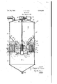
- a still further object is to provide an improved I comprises, essentially, a body portion or tank ll,
- evaporator in which the pumping equipment is mounted within the evaporator as an integral part of the evaporator assembly, so that the entire circulation and agitation of the fluid is confined within the evaporator tank, whereby to obtain a more uniform velocity of the fluid through the evaporator assembly, and a more having end closure portions or covers l2 and i3 which may be secured to the tank in any suitable manner.
- the solution or liquor to be treated is delivered to the interior of the tank through a conduit or feed pipe H which is suitably secured to the upper closure portion l2 of the tank. Disposed intermediate the end portions l?
- the evaporator or heater unit which is preferably of circular form, and selfenclgsed, the heater being generally designated at l5, and includes a chamber I6 arranged concentrically of the tank II.
- the chamber enclosing structure is, by preference, built into and supported by the tank II and comprises horizontal plates or wall portions I1 and IS, a cylindrical inner wall l9, and a cylindrical outer wall 20.
- the wall 19 serves, in addition, to deflne a central well or chamber 2
- the wall portions I1, l8, l9 and 20 may be securedtogether as by welding, riveting or in any other desired manner (not shown), it being noted that the outer cylindrical wall element 20 also constitutes an intermediate outside wall of the evaporator tank or pan structure, being secured to the wall sections above and below as by external flange joints 22. t
- a plurality of equally spaced tubes 23 extend between and through the plate members" and IS with their ends expanded or otherwise secured in fluid-tight relation to the plates, the tubes opening into the tank chamber so that the fluid admitted to the interior oi the tank may be cycled through them.
- a pipe or conduit 24 is, by preference, secured to the outer wall 20, and is directed into the chamber I6, for conducting steam or other suitable heating medium into the chamber. The heating fluid circulates about the tubes23 within the chamber l6, thus heat-,
- the evaporator assembly is provided, in the central wall or chamber portion 2
- the pump assembly includes, by preference, a. suction or entrance cone 21, a runner or propeller 28, stationary diffuser vanes 29, and a discharge cone 30,.
- the pump assembly is preferably suspended from points above the heater unit by means of tie rods 3
- the lower ends of the tie rods are pivotally mounted on pins 33 engaglngj eye-bracket members 34, the
- Each brace is pivotally secured at its inner end to one of the brackets 34 by means of the 'pin 33, and the opposite end 31 is adjustably secured to the side wall ofthe'tank in any desired manner, for example, suitable shims 38 being provided between the end 3'! of each brace, and the wall of the tank, for purposes of lateral adjustment.
- the pump or agitator is driven preferably by an electric motor 39 which is, or may be supported extemaliy of the tank on the closure por-' tion l2.
- the motor shaft 40 is suitably connected to a stub shaft 4
- a bevel gear 43 is secured to the inner end of the stub shaft 4
- the housing 42 enclosingthe bevel gears may, of course, contain a suitable quantity of lubricant for the gears.
- the pump propeller is so' formed that when the pump is driven by the mechanism above described, the liquor in the upper-portion 4B. of the tank chamber will be forced.
- the improved pumpingarrangement herein fully described is designed to obtain a uniform velocity of flow of the liquor through the evaporator, and to effect a more rapid and ellicient evaporating action than has heretofore been possible of attainment in the older prevailing installations. It will be observed that the discharge cone ill is so formed as to restore the velocity of the fluid discharging through the pump.
- the entire pumping equipment is suspended from above the evaporator or heater unit ll in such a manner as to relieve theheater structure from supporting any more than a negligible part of the weight of 1 the pumping equipment.
- the diffuser vanes 29 are, or may be, cast integrally with the discharge cone 30 as a manufacturing expedient, and to minimize the overall length of,
- the entire evaporator assembly including the internally mounted pumping and circulating equipment, is designed to facilitate ease in assembly, and to minimize-space requirements'.
- a liquid circulating and heat exchange unit disposed-below the normal level of liquid in the container, said unit including a horizontal tank of substantially annular form through which-the liquid is to be passed for heat exchange purposes, a pump within the central opening of the tank, the pump being of vertical shaft type and including a propeller type impeller, a plurality of substantially vertical, [stationary diffuser vanes disposed immediately'adjacent to and extending substantially beyond the pump impeller, an open end tubular body forming a casing about the impeller and constituting a support for said diffuser vanes, the tubular body being formed of two sections connected in a zone substantially between the impeller and vanes, the lower section of the tubular body being flared in a direction away from the pump impeller discharge and terminating in a bell end in a zone substantially below said annular tank, the tank, pump, vanes and tubular body being supported in assembly entirely by theside walls of the container, in a manner to pro-'- vide
Landscapes
- Chemical & Material Sciences (AREA)
- Chemical Kinetics & Catalysis (AREA)
- Structures Of Non-Positive Displacement Pumps (AREA)
Description
525,193s. R. v. COOK 1 2,106,295 EVAPORATOR Filed June 13, 1935 INVENTOR.
ROBERT. M COOK ATTORNEY.
Patented Jan. 25, 1938 PATENT OFFICE EVAPORATOR Robert v. Cook, mm, m, asslgnor to Fairbanks, Morse & Company, Chicago, 111., a corporation of Illinois Application June 13, 1935, Serial No. 26,409
1 Claim.
This invention relates .to improvements in evaporators, and more particularly to improved circulating and agitating means for evaporators, or the like.
In older prevailing evaporator installations of r a type employing forced circulation of the liquor or fluid to be treated, the fluid is generally transferred from the bottom of the evaporator tank to the top of the tank by means of a pump of suitable type. The piping and pumping equipment in such installations is, in nearly all cases, arranged externally of the evaporator tank; hence, during the transfer of the liquid from the lower to the upper portion of the tank, the fluid is entirely removed therefrom. The loss of heat resulting from the removal of the fluid from the tank during such transfer, materially affects the efllciency of the evaporator system. In addition, the arrangement and disposition of the piping and pumping equipment externally of the evaporator adds considerably to the cost and space requirements of the installation. Hence, it is an object of the present invention to provide an improved evaporator assembly in which the circulating and agitating equipment is operatively secured entirely within the evaporator tank. whereby to secure an increased hydraulic and thermaleiflciency of the system, and to obviate the several objectionable features of the older prevailing installations, hereinabove indicated.
Another object is to provide, in connection with apparatus of the type described, an improved pumping assembly mounted within the evaporator chamber for circulating the fluid downwardly in the central portion of the chamber, through the pump assembly and thence upwardly in the evaporator chamber.
A further object is to provide an improved evaporator of the type described, in which the fluid circulating pump is suspended, within the evaporator, from the walls of the evaporator tank, the arrangement being such that the load of the pump and appurtenant parts is distributed over the vertical walls of the tank by spaced tie rods or other tension members.
Yet a further object of the invention is attained in a pump structure of improved type for circulation of liquor within the tank or pan of an evaporator, the pump assembly including a suction or entrance cone, a runner, a diifuser and a discharge-cone, the latter element functioning in the operation of the pump to restore the velocity of the fluid discharging through the pump- A still further object is to provide an improved I comprises, essentially, a body portion or tank ll,
. evaporator in which the pumping equipment is mounted within the evaporator as an integral part of the evaporator assembly, so that the entire circulation and agitation of the fluid is confined within the evaporator tank, whereby to obtain a more uniform velocity of the fluid through the evaporator assembly, and a more having end closure portions or covers l2 and i3 which may be secured to the tank in any suitable manner. In the chemical or heat treatment of fluids, the solution or liquor to be treated is delivered to the interior of the tank through a conduit or feed pipe H which is suitably secured to the upper closure portion l2 of the tank. Disposed intermediate the end portions l? and I3 of the tank II, is an evaporator or heater unit, which is preferably of circular form, and selfenclgsed, the heater being generally designated at l5, and includes a chamber I6 arranged concentrically of the tank II. The chamber enclosing structure is, by preference, built into and supported by the tank II and comprises horizontal plates or wall portions I1 and IS, a cylindrical inner wall l9, and a cylindrical outer wall 20. The wall 19 serves, in addition, to deflne a central well or chamber 2| opening into the tank chamber, the well being provided for a purpose which will presently appear. The wall portions I1, l8, l9 and 20, may be securedtogether as by welding, riveting or in any other desired manner (not shown), it being noted that the outer cylindrical wall element 20 also constitutes an intermediate outside wall of the evaporator tank or pan structure, being secured to the wall sections above and below as by external flange joints 22. t
A plurality of equally spaced tubes 23 extend between and through the plate members" and IS with their ends expanded or otherwise secured in fluid-tight relation to the plates, the tubes opening into the tank chamber so that the fluid admitted to the interior oi the tank may be cycled through them. A pipe or conduit 24 is, by preference, secured to the outer wall 20, and is directed into the chamber I6, for conducting steam or other suitable heating medium into the chamber. The heating fluid circulates about the tubes23 within the chamber l6, thus heat-,
ing the tubes and, by conduction, the liquor passsuiting rapid heat transfer causing evaporation of the fluid.
' 'As a means for agitating and circulating the liquor within the tank and through the heater unit IS, the evaporator assembly is provided, in the central wall or chamber portion 2| of the tank, with a propeller type pump, generally designated at 28, the pump being, by preference, dependingly supported from the vertical tank walls, by means presently to be described. The pump assembly includes, by preference, a. suction or entrance cone 21, a runner or propeller 28, stationary diffuser vanes 29, and a discharge cone 30,. The pump assembly is preferably suspended from points above the heater unit by means of tie rods 3| which are pivotally secured at their upper ends to eye-brackets 32 secured as by riveting to'the side walls of the tank. The lower ends of the tie rods are pivotally mounted on pins 33 engaglngj eye-bracket members 34, the
' the wall of the tank II and the eye-brackets 34.
Each brace is pivotally secured at its inner end to one of the brackets 34 by means of the 'pin 33, and the opposite end 31 is adjustably secured to the side wall ofthe'tank in any desired manner, for example, suitable shims 38 being provided between the end 3'! of each brace, and the wall of the tank, for purposes of lateral adjustment.
The pump or agitator is driven preferably by an electric motor 39 which is, or may be supported extemaliy of the tank on the closure por-' tion l2. The motor shaft 40 is suitably connected to a stub shaft 4| which extends into a gear housing 42 mounted externally of the tank.
A bevel gear 43 is secured to the inner end of the stub shaft 4| and engages a bevel gear 44 suitably secured to a stub shaft 45 which extends 6O by. a connecting shaft 41, the ends of which are secured to the stub shafts 45 and 46 in any desired manner. The housing 42 enclosingthe bevel gears may, of course, contain a suitable quantity of lubricant for the gears. The pump propeller is so' formed that when the pump is driven by the mechanism above described, the liquor in the upper-portion 4B. of the tank chamber will be forced. downwardly, as indicated by the arrows in the drawing, into the-lower tank portion 49, first outwardly and thence upwardly through the tubes 23 of the heater l5, and returned to the chamber portion 48. A circular disc or plate is disposed between the upperv end of the heater unit and the upper edge of the suction cone 21. Hence, during the operation of the pump, fluid contained in the chamber portion 48 ofthe tank, must necessarily pass through the pump 26 to the chamber portion 49, since the plate 50 effectively prevents passage of fluid through the well portionfl of the evaporatorassembly. The treated fluid is, or may be removed from the bottom portion of the tank ll through a pipe or conduit it having one end thereof secured to the lower cover I3. I
It will be readily understood that by disposing the entire circulating and agitating equipment within the evaporator tank, increased hydraulic and thermal efliciencies are obtained, since the fluid is not removed from the tank at any time during thetreating process. In the older prevailing evaporator installations, the fluid in process was conveyed from the bottom of the tank to the top of the tank through a conduit and pumping system arranged exteriorly of the tank. Hence, during the evaporation process, the circulation of fluid was effected partly through the evaporator tank and partly through an external conduit system. In the presently improved arrangement, the circulation is effected downwardly through the pump assembly and thence upwardly through the heater tubes 23, the complete circulation taking place entirely within the tank II. The improved pumpingarrangement herein fully described, is designed to obtain a uniform velocity of flow of the liquor through the evaporator, and to effect a more rapid and ellicient evaporating action than has heretofore been possible of attainment in the older prevailing installations. It will be observed that the discharge cone ill is so formed as to restore the velocity of the fluid discharging through the pump. In the. presently improved arrangement, the entire pumping equipment is suspended from above the evaporator or heater unit ll in such a manner as to relieve theheater structure from supporting any more than a negligible part of the weight of 1 the pumping equipment. The diffuser vanes 29 are, or may be, cast integrally with the discharge cone 30 as a manufacturing expedient, and to minimize the overall length of,
the pump, and hence of the tank. It will be evident that the entire evaporator assembly, including the internally mounted pumping and circulating equipment, is designed to facilitate ease in assembly, and to minimize-space requirements'.
The description of the device, its parts, their combination and purposes, has. for brevity, been directed to a device utilized for evaporating liquids by the application of heat. Obviously, the principles of construction and design are equally applicable to apparatus for heat exchanging processes generally, such as cooling equipment, cooking and many others, ,and' accordingly the invention is not to be understood asrestricted by stated fields of application. Itwill, of course, be understood that thepresent. detailed description of partrand the accompanying drawing relate only to a single preferred executional embodiment or the invention 'and that substantial changes-may be made in the described arrangement and construction of parts, without departing from the spirit'and full intended scope of the invention, as deflned by the appended claim.
I claim:
Incombination in a vertical container for the thermal treatment of liquids, a liquid circulating and heat exchange unit disposed-below the normal level of liquid in the container, said unit including a horizontal tank of substantially annular form through which-the liquid is to be passed for heat exchange purposes, a pump within the central opening of the tank, the pump being of vertical shaft type and including a propeller type impeller, a plurality of substantially vertical, [stationary diffuser vanes disposed immediately'adjacent to and extending substantially beyond the pump impeller, an open end tubular body forming a casing about the impeller and constituting a support for said diffuser vanes, the tubular body being formed of two sections connected in a zone substantially between the impeller and vanes, the lower section of the tubular body being flared in a direction away from the pump impeller discharge and terminating in a bell end in a zone substantially below said annular tank, the tank, pump, vanes and tubular body being supported in assembly entirely by theside walls of the container, in a manner to pro-'- vide a substantially unobstructed circulation space above the said assembly, a liquid inlet in the top of the tank, a liquid outlet at thebottom thereof, a vertical pump shaft extendin from the pump impeller to a point externally of the container, and a driving motor for said shaft, located exteriorly of the container.
'ROBERT V. COOK.
Priority Applications (1)
| Application Number | Priority Date | Filing Date | Title |
|---|---|---|---|
| US26409A US2106295A (en) | 1935-06-13 | 1935-06-13 | Evaporator |
Applications Claiming Priority (1)
| Application Number | Priority Date | Filing Date | Title |
|---|---|---|---|
| US26409A US2106295A (en) | 1935-06-13 | 1935-06-13 | Evaporator |
Publications (1)
| Publication Number | Publication Date |
|---|---|
| US2106295A true US2106295A (en) | 1938-01-25 |
Family
ID=21831663
Family Applications (1)
| Application Number | Title | Priority Date | Filing Date |
|---|---|---|---|
| US26409A Expired - Lifetime US2106295A (en) | 1935-06-13 | 1935-06-13 | Evaporator |
Country Status (1)
| Country | Link |
|---|---|
| US (1) | US2106295A (en) |
Cited By (4)
| Publication number | Priority date | Publication date | Assignee | Title |
|---|---|---|---|---|
| US2697486A (en) * | 1950-12-28 | 1954-12-21 | Swift & Co | Antibridginc apparatus |
| US2944600A (en) * | 1958-02-24 | 1960-07-12 | Manistee Engineering Company | Multi-blade circulator and evaporator construction |
| US3185212A (en) * | 1963-04-22 | 1965-05-25 | Irma Amelia Howard | Fluid heat transfer system |
| US3498357A (en) * | 1967-08-22 | 1970-03-03 | Thomas M Hamill | Internal circulation inducing syrup concentrating vacuum pan |
-
1935
- 1935-06-13 US US26409A patent/US2106295A/en not_active Expired - Lifetime
Cited By (4)
| Publication number | Priority date | Publication date | Assignee | Title |
|---|---|---|---|---|
| US2697486A (en) * | 1950-12-28 | 1954-12-21 | Swift & Co | Antibridginc apparatus |
| US2944600A (en) * | 1958-02-24 | 1960-07-12 | Manistee Engineering Company | Multi-blade circulator and evaporator construction |
| US3185212A (en) * | 1963-04-22 | 1965-05-25 | Irma Amelia Howard | Fluid heat transfer system |
| US3498357A (en) * | 1967-08-22 | 1970-03-03 | Thomas M Hamill | Internal circulation inducing syrup concentrating vacuum pan |
Similar Documents
| Publication | Publication Date | Title |
|---|---|---|
| US3933576A (en) | Evaporation of radioactive wastes | |
| US3622387A (en) | Evaporator or cooking apparatus | |
| US4329198A (en) | Apparatus for forced circulation evaporation | |
| US2582899A (en) | Autoclave reactor | |
| US2106295A (en) | Evaporator | |
| US2071624A (en) | Heat transfer apparatus | |
| US3078999A (en) | Sludge digester | |
| US3595308A (en) | Apparatus for cooling liquids | |
| US2522948A (en) | Liquid cooling and storage apparatus | |
| US2782008A (en) | Heat exchangers for fluids | |
| US1735980A (en) | Process of evaporation | |
| US3255887A (en) | Sludge digester | |
| US1489571A (en) | Centrifugal pump | |
| US2764476A (en) | Reaction tank and thermo-regulator system | |
| US4255060A (en) | Homogenizing device | |
| US2174318A (en) | Unit tank heater | |
| US2188839A (en) | Milk cooler | |
| US2723109A (en) | Vapor to liquid heat exchanger | |
| US1890152A (en) | Vacuum still | |
| US884610A (en) | Steam-regenerator. | |
| US2570211A (en) | Falling film evaporator | |
| US1877322A (en) | Method and apparatus for heat exchanges | |
| US2594142A (en) | Crystallizing apparatus | |
| JP3880461B2 (en) | Multi-tube heat transfer stirrer | |
| US1634304A (en) | Centrifugal pump |