US2104253A - Luminescent screen and method of use - Google Patents
Luminescent screen and method of use Download PDFInfo
- Publication number
- US2104253A US2104253A US655784A US65578433A US2104253A US 2104253 A US2104253 A US 2104253A US 655784 A US655784 A US 655784A US 65578433 A US65578433 A US 65578433A US 2104253 A US2104253 A US 2104253A
- Authority
- US
- United States
- Prior art keywords
- screen
- temperature
- cathode
- anode
- television
- Prior art date
- Legal status (The legal status is an assumption and is not a legal conclusion. Google has not performed a legal analysis and makes no representation as to the accuracy of the status listed.)
- Expired - Lifetime
Links
- 238000000034 method Methods 0.000 title description 8
- 238000010438 heat treatment Methods 0.000 description 9
- 229910052751 metal Inorganic materials 0.000 description 8
- 239000002184 metal Substances 0.000 description 8
- 230000005855 radiation Effects 0.000 description 7
- GUVRBAGPIYLISA-UHFFFAOYSA-N tantalum atom Chemical compound [Ta] GUVRBAGPIYLISA-UHFFFAOYSA-N 0.000 description 6
- 238000005286 illumination Methods 0.000 description 4
- 239000000463 material Substances 0.000 description 4
- 229910052715 tantalum Inorganic materials 0.000 description 4
- 239000004020 conductor Substances 0.000 description 3
- 230000000007 visual effect Effects 0.000 description 3
- WABPQHHGFIMREM-UHFFFAOYSA-N lead(0) Chemical compound [Pb] WABPQHHGFIMREM-UHFFFAOYSA-N 0.000 description 2
- 239000003870 refractory metal Substances 0.000 description 2
- 230000001360 synchronised effect Effects 0.000 description 2
- ZOKXTWBITQBERF-UHFFFAOYSA-N Molybdenum Chemical compound [Mo] ZOKXTWBITQBERF-UHFFFAOYSA-N 0.000 description 1
- 230000009471 action Effects 0.000 description 1
- 238000007796 conventional method Methods 0.000 description 1
- 238000001816 cooling Methods 0.000 description 1
- 230000000694 effects Effects 0.000 description 1
- 238000010894 electron beam technology Methods 0.000 description 1
- 230000004907 flux Effects 0.000 description 1
- 239000011888 foil Substances 0.000 description 1
- 230000006872 improvement Effects 0.000 description 1
- 150000002739 metals Chemical class 0.000 description 1
- 229910052750 molybdenum Inorganic materials 0.000 description 1
- 239000011733 molybdenum Substances 0.000 description 1
- 230000010287 polarization Effects 0.000 description 1
- 239000011819 refractory material Substances 0.000 description 1
- 230000001105 regulatory effect Effects 0.000 description 1
- 230000007480 spreading Effects 0.000 description 1
- 238000004544 sputter deposition Methods 0.000 description 1
- WFKWXMTUELFFGS-UHFFFAOYSA-N tungsten Chemical compound [W] WFKWXMTUELFFGS-UHFFFAOYSA-N 0.000 description 1
- 229910052721 tungsten Inorganic materials 0.000 description 1
- 239000010937 tungsten Substances 0.000 description 1
Images
Classifications
-
- H—ELECTRICITY
- H01—ELECTRIC ELEMENTS
- H01J—ELECTRIC DISCHARGE TUBES OR DISCHARGE LAMPS
- H01J29/00—Details of cathode-ray tubes or of electron-beam tubes of the types covered by group H01J31/00
- H01J29/02—Electrodes; Screens; Mounting, supporting, spacing or insulating thereof
- H01J29/10—Screens on or from which an image or pattern is formed, picked up, converted or stored
- H01J29/16—Incandescent screens
Definitions
- a luminescent screen giving a pure white light
- a screen which may be luminously excited to a greater degree than the known screens of the fluorescent type
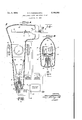
- Figure l is a longitudinal sectional view through an oscillight or television receiver tube embodying this invention, the circuit connections being shown diagrammatically.
- Figure 2 is a cross sectional view taken as indicated by the line 2-4 in Figure 1.
- Luminescent screens of this character have the advantages of large luminous efiiciences with low power input, but the unit brilliancy is low.
- the light from such fluorescent screens is very definitely colored, usually a bluish or greenish tinge, making it undesirable for television use.
- the purpose of this invention is to provide a screen which shows the trace of the cathode ray beam in pure white light.
- this invention comprises the combination with a source of cathode rays of a screen formed of thin metal, of sufllcient thinness to be raisedto incandescence by the impact of the rays.
- a source of cathode rays of a screen formed of thin metal of sufllcient thinness to be raisedto incandescence by the impact of the rays.
- the invention comprises broadly the steps of generating; a pencil or beam of cathode rays, directing the rays against a screen formed from a thin sheet of refractory material so as to raise the point of impact to incandescence, deflecting the beam so that it impinges upon successive elementary areas of the screen, and meanwhile maintaining the sheet at a uniform predetermined temperature, preferably at a low red heat, around 800 K.
- the beam may then be modulated in accordance with a television signal to produce a brilliant eifective oscillographic or, if desired, a television image, with all of the beam power effective to produce light.
- the form of the invention ilhistrated ini having at one-coda reentrant stem 2 which carries anelectron
- the typeof gun used cathoderay beam of highv intensity.
- the cathode (not shown) is heated by current supplied by battery 4, or like source, through leads 5 and l, emitting electrons which are attracted by a conical projection I on a circular anode I and pass through a beam canal in the anode to form the required beam of cathode rays.
- the anode is welded to a support II, this in turn being supported from a clamp ring II.
- a lead wire I 2 connects to the anode support and is brought out through a side seal it to which the anode battery II or similar source is connected, the other end of the battery being connected to one cathode lead through anode wire it.
- the intensity of the beam is regulated by a control electrode or grid i1, mounted on lead I 9 sealed through the stem, and connected by grid wire 20 to the television receiver, or other modulator as desired.
- the cathode lead 5 is also connected to the receiver through lead wire 2
- an arm 22 extending away from the anode at an angle and terminating in a cup 24 which is used to vaporize a volatile metal on the walls of the tube.
- a spring contact arm 25 extends from the opposite side of the anode, and terminates in a contact 26 which is held by the pressure of the arm against the wall of the tube and is therefore in contact with the film of metal deposited from the cup 24. The him being energized at anode potential and covering the barrel of the tube, the beam is thus protected from the influence of extaneous potentials.
- the end of the envelope opposite the gun is slightly expanded to form a screen chamber 21, into which is sealed a heat screen assembly supported by a screen stem 28.
- This screen assembly preferably comprises a rectangular wire frame I! mounted on frame leads 3
- a cross bar ll provides additional strength.
- Insulating sliders I! of lava or similar material are connected by a mounting bar 33 and are movable along the framework.
- a heat screen II of any desired shape, but preferably rectangular, is welded to the top of the frame, and to the mounting bar.
- Springs 85 welded at one end to the frame press against the sliders 32 and maintain the screen 34 under tension.
- Flexible leads 36 connect the mounting bar to screen leads l1, sealed through the stem. A circuit is thereby established so that a source of current 39 may be used to heat the entire screen to a uniform predetermined temperature by passing current through the screen.
- the screen itself should be of a refractory ,metal capable of being raised to incandescence by the impact of the beam, and it has been found that tantalum foil formed as described in the application of Gardner and Varian, Serial Number 637,772, filed October 14, 1932, is entirely satisfactory.
- the type of electron gun used is highly emcient, delivering as much as 80% of the total emission of the cathode into the active electron stream, and cathode ray beams carrying as much as 10 milliamperes are readily producible, the
- r is preferably that shown in detail in the copending application of Gardner and Brolly, Serial. No. 614,500,.vetted May- 31, 1932, this form of cathode ray projector being capable of producing a entire electron emflonof thescreen as a verynn'e spot.
- the beam is 4- Qdefiected'to form a trace by the magnetic field produced by passing an alternating current through coils, so that the beam sweeps across the screen from side to side and falls only instantaneously upon any given elementary area.
- the current for these coils is supplied by a high frequency oscillator as shown.
- a similar set ll of coils arranged at right angles to the coils l. is used to deflect the beam in the opposite direction, one of these coils being omitted in the drawing for sake of clarity.
- anode potential of 5,000-7,000 volts is used, so that from 50 to 70 watts are expended in the beam, this power being available for heating the screen at the point of impact of the beam.
- the device is ideally adapted to reproduce television pictures
- I have shown means for modulating the beam in accordance with signals as received by radio on a television receiver.
- the high and low frequency oscillators are synchronized with the picture signals in such a manner as to produce a proper image.
- I have not shown the oscillators connected to the receiver, asthey might be driven, for example, by a synchronous motor operating from the same power line as the television transmitter.
- a suitable thickness of tantalum foil has been found, as above stated, to be from 50 to l00 10- inches.
- the power increases so rapidly with temperature that the cooling time for high temperatures will be extremely short compared to that of low temperatures.
- a base, or polarizing temperature may thus be maintaind over the whole screen, from a source apart from the beam.
- This polarizing temperature may be 800 without disturbing the detail, thus allowing all of the beam intensity to be results. It is possible also, because of the sluggishness of the screen at low temperatures, to supply this polarizing power from A. C. mains, instead of a battery.
- the invention as described has been used to form effective television images of extreme brilliancy, the pictures so formed on the metal screen being used as alight source for projection lenses, suflicient light being obtained to allow the pictures to be projected on a screen greatly en,- larged.
- the illumination is of the order of 2 candlepower per watt of input energy. With 70 watts input in the beam, and a polarizing heat of 800, thus maintaining the screen at a dull, bare- 1y visible red heat during the continuous movement of the beam spot, the television image produced on a screen of this type an inch and a half to two inches square is so brilliant that the screen cannot be viewed directly, and when projected the effect of the illumination is substantially twice to four times that available with home moving picture outfits using a 100 watt lamp.
- the actual luminous flux is, of course, much less than that of the home projection equipment, but in the case of the screen of my invention it is the image of the luminous source itself which is projected, whereas in the case of the motion picture film approximately 90% of the I on infalling light is absorbed by the film. It is therefore possible, using screens of this type, to project television images in rooms having a fair degree of general illumination, and to a size of from one to five feet square, depending on the general illumination level and the amount of power expended in the cathode ray beam, together with the constants of the screen itself.
- the aesthetic value of the picture is the same as the projected pictures to which the public is now accustomed, from the point of view of color.
- the color values of the picture projected from the screen of my invention are identical with the values in the usual motion picture, as an incandescent source is used in both cases, and the use of the heat screen as here described has completely removed the objection formerly held to the older colored fluorescent screen images I claim:
- luminescent means disposed wholly within said envelope in the path of said rays, said means consisting of a tantalum sheet having a thickness from 50 to 100 10- inches.
- Means for producing an effective visual image comprising the combination of an envelope containing a cathode and anode adapted to produce a beam of cathode rays, a thin refractory metal sheet supported solely by its edges disposed in the path of said rays, means for deflecting said beam two-dimensionally to scan elemental areas of said sheet to raise the entire cross section beneath said areas to an incandescent temperature, and means for heating said sheet to a uniform temperature.
- the method of forming a visual image which comprises resistively heating a conductor to a uniform temperature and simultaneously heating successive elementary volumes including opposing faces of said conductor to varying luminous temperatures by electron impact.
- a cathode ray apparatus the combination of an envelope containing a cathode and anode cooperating to produce a defined beam of cathode rays, and an opaque metal luminescent screen, said screen being of such thin section that the impact area of said screen, together with the remainder of the section of said screen below said area, is raised to incandescence.
Landscapes
- Cathode-Ray Tubes And Fluorescent Screens For Display (AREA)
Description
Jan. 4, 1938. P. T. FARNSWORTH 2,
LUMINESCENT SCREEN AND METHOD OF USE Filed 1955 m a m 0 W 0 M 4 ll'l a k M u a a a a m a u a ,4 a a a n H 9 u 2 a ifiiidiriiifiirvvvfi e 3. .3 j l a!!! 0 y 4 Low REQUENcy OSCILLA Top HIGH FREQUENCY oscmurop TELEVISION RECEIVER.
INVENTOR,
PHI/.0 7' ARNSWOR TH.
TTORNEY 'uumukrmsummm H UNITED STATES LUHINISOENT scam AND USE mrnon or Pililo '1. Farnaworth, San Francisco, Calif asoilnor to I'arnlworth Television Incorporated. a corporation of California Application February 8, 1933, Serial No. 855,784.
8 Claims. (CL 250-275) My invention relates to luminescent screens for use in cathode ray apparatus, such as oscilloscope or oscillographic tubes, and oscillights or television receiver tubes, this application being an improvement on the invention disclosed in the Farnsworth and Gardner application, Serial Number 614,501, filed May 31, 1932.
Among the objects of my invention are: To provide a luminescent screen giving a pure white light; to provide a screen which may be luminously excited to a greater degree than the known screens of the fluorescent type; to provide a luminescent screen in the form of a. thin sheet of refractory metal which is stable in operation and is strong mechanically; to provide a means of biasing such a screen by heating the entire area to a uniform temperature, said means being independent of the action of the cathode ray beam; and to provide a means for increasing the visual efficiency of the heating produced by a cathode ray beam.
Other objects of my invention will be apparent or will be specifically pointed out in the description forming a part of this specification, but I do not limit myself to the embodiment of my invention herein described, as various. forms may be adopted within the scope of the claims.
Referring to the drawing:
Figure l is a longitudinal sectional view through an oscillight or television receiver tube embodying this invention, the circuit connections being shown diagrammatically.
Figure 2 is a cross sectional view taken as indicated by the line 2-4 in Figure 1.
For many years it has been customary to form the luminescent screen used in cathode ray oscillograph tubes and the like, of materials which fiuoresce under the impact of the rays. Luminescent screens of this character have the advantages of large luminous efiiciences with low power input, but the unit brilliancy is low. When beam velocities are increased, only slight increases in light are obtained with large increases in power, and there is a strong tendency for the material to break down and become inactive under bombardment.- Moreover, the light from such fluorescent screens is very definitely colored, usually a bluish or greenish tinge, making it undesirable for television use. The purpose of this invention is to provide a screen which shows the trace of the cathode ray beam in pure white light. Although the method here employed is less sensitive on small power inputs than is the fluorescent screen, it has been found that with large power inputs the efficiency may approach that of the conventional screen, in addition to giving eflective images vastly more brilliant than possible with conventional methods.-
Broadly considered from the aspect of the apparatus employed, this invention comprises the combination with a source of cathode rays of a screen formed of thin metal, of sufllcient thinness to be raisedto incandescence by the impact of the rays. These requirements are met in a preferred form by a tantalum screen having a thickness of from 50 to 100x10 inches.
The operation of a heat screen without polarization has been fully described in application, Serial Number 614,501, filed May 31, 1932, above mentioned, wherein it has been shown that as a cathode ray beam is moved constantly from one elementary area to another, the mass of material in the path of the beam is so small that its rise to incandescence is practically instantaneous. Furthermore, conduction to adjacent areas is so restricted that heat loss by radiation cools the bombarded area before the incandescence can spread appreciably. Should the beam spot be applied continuously to one location on the screen there would, of course, be spreading of the luminous area 'no matter how great the thermal resistance. The practically continuous movement of the spot is therefore, an essential feature in the operation of any heat screen.
In operating such a heat screen as above described, I have found that as the power necessary to heat the screen increases rapidly with temperature, additional means for maintaining the screen at a uniform base temperature can be advantageously used, thus relieving thenecessity of including a relatively large amount of power in the electron beam, as the screen does not begin to emit light until the screen temperature rises to around 800 Kelvin, and the beam power necessary to raise'the screen to that temperature is wasted from the point of View of light.
Considering the method involved,the invention comprises broadly the steps of generating; a pencil or beam of cathode rays, directing the rays against a screen formed from a thin sheet of refractory material so as to raise the point of impact to incandescence, deflecting the beam so that it impinges upon successive elementary areas of the screen, and meanwhile maintaining the sheet at a uniform predetermined temperature, preferably at a low red heat, around 800 K. The beam may then be modulated in accordance with a television signal to produce a brilliant eifective oscillographic or, if desired, a television image, with all of the beam power effective to produce light.
The form of the invention ilhistrated ini having at one-coda reentrant stem 2 which carries anelectron The typeof gun used cathoderay beam of highv intensity. The cathode (not shown) is heated by current supplied by battery 4, or like source, through leads 5 and l, emitting electrons which are attracted by a conical projection I on a circular anode I and pass through a beam canal in the anode to form the required beam of cathode rays. The anode is welded to a support II, this in turn being supported from a clamp ring II. A lead wire I 2 connects to the anode support and is brought out through a side seal it to which the anode battery II or similar source is connected, the other end of the battery being connected to one cathode lead through anode wire it.
The intensity of the beam is regulated by a control electrode or grid i1, mounted on lead I 9 sealed through the stem, and connected by grid wire 20 to the television receiver, or other modulator as desired. The cathode lead 5 is also connected to the receiver through lead wire 2|.
Welded to one side of the anode 8 is an arm 22 extending away from the anode at an angle and terminating in a cup 24 which is used to vaporize a volatile metal on the walls of the tube. A spring contact arm 25 extends from the opposite side of the anode, and terminates in a contact 26 which is held by the pressure of the arm against the wall of the tube and is therefore in contact with the film of metal deposited from the cup 24. The him being energized at anode potential and covering the barrel of the tube, the beam is thus protected from the influence of extaneous potentials.
The end of the envelope opposite the gun is slightly expanded to form a screen chamber 21, into which is sealed a heat screen assembly supported by a screen stem 28. This screen assembly preferably comprises a rectangular wire frame I! mounted on frame leads 3|. A cross bar ll provides additional strength. Insulating sliders I! of lava or similar material are connected by a mounting bar 33 and are movable along the framework. A heat screen II of any desired shape, but preferably rectangular, is welded to the top of the frame, and to the mounting bar. Springs 85 welded at one end to the frame press against the sliders 32 and maintain the screen 34 under tension. Flexible leads 36 connect the mounting bar to screen leads l1, sealed through the stem. A circuit is thereby established so that a source of current 39 may be used to heat the entire screen to a uniform predetermined temperature by passing current through the screen.
The screen itself should be of a refractory ,metal capable of being raised to incandescence by the impact of the beam, and it has been found that tantalum foil formed as described in the application of Gardner and Varian, Serial Number 637,772, filed October 14, 1932, is entirely satisfactory.
The type of electron gun used is highly emcient, delivering as much as 80% of the total emission of the cathode into the active electron stream, and cathode ray beams carrying as much as 10 milliamperes are readily producible, the
r is preferably that shown in detail in the copending application of Gardner and Brolly, Serial. No. 614,500,.iiled May- 31, 1932, this form of cathode ray projector being capable of producing a entire electron emflonof thescreen as a verynn'e spot. I
The beam is 4- Qdefiected'to form a trace by the magnetic field produced by passing an alternating current through coils, so that the beam sweeps across the screen from side to side and falls only instantaneously upon any given elementary area. The current for these coils is supplied by a high frequency oscillator as shown. A similar set ll of coils arranged at right angles to the coils l. is used to deflect the beam in the opposite direction, one of these coils being omitted in the drawing for sake of clarity.
When an alternating current is passed through coils II at a different frequency from that in coils ll, the trace of the ray will describe a rectangular area on the screen, traversing each element of the field successively. The oscillator supplying this second set of coils is designated as a low frequency oscillator.
In practice, an anode potential of 5,000-7,000 volts is used, so that from 50 to 70 watts are expended in the beam, this power being available for heating the screen at the point of impact of the beam.
As the device is ideally adapted to reproduce television pictures, I have shown means for modulating the beam in accordance with signals as received by radio on a television receiver. In this case the high and low frequency oscillators are synchronized with the picture signals in such a manner as to produce a proper image. As there are many ways of producing this synchronism, I have not shown the oscillators connected to the receiver, asthey might be driven, for example, by a synchronous motor operating from the same power line as the television transmitter.
It is necessary to provide a screen of thickness just suiiicient to allow its being heated to incandescence when the beam spot moves at the required rate. A suitable thickness of tantalum foil has been found, as above stated, to be from 50 to l00 10- inches. The total radiation required to heat the screen is given by the formula W=SAT where T=degrees Kelvin, A=area,
s=5 10 watts .(for tantalum).
An idea of the power required for a given temperature is tabulated in the table below:
As will be seen, the power increases so rapidly with temperature that the cooling time for high temperatures will be extremely short compared to that of low temperatures. A base, or polarizing temperature may thus be maintaind over the whole screen, from a source apart from the beam. This polarizing temperature may be 800 without disturbing the detail, thus allowing all of the beam intensity to be results. It is possible also, because of the sluggishness of the screen at low temperatures, to supply this polarizing power from A. C. mains, instead of a battery.
It is of course possible to adjust beam power and polarizing power to compensate for various thicknesses of metal foil, and for various other used for producing visible metals than tantalum. Tungsten, molybdenum and other screens capable of being raised to incandenscence without disintegration or excessive sputtering are satisfactory.
Obviously, also, means other than resistive heating may be employed to raise the temperature of the screen as a whole. Infra-red radiation has been employed with excellent results, and an auxiliary unmodulated cathode ray beam, is an example of another way that the screen may be polarized.
The invention as described has been used to form effective television images of extreme brilliancy, the pictures so formed on the metal screen being used as alight source for projection lenses, suflicient light being obtained to allow the pictures to be projected on a screen greatly en,- larged. The illumination is of the order of 2 candlepower per watt of input energy. With 70 watts input in the beam, and a polarizing heat of 800, thus maintaining the screen at a dull, bare- 1y visible red heat during the continuous movement of the beam spot, the television image produced on a screen of this type an inch and a half to two inches square is so brilliant that the screen cannot be viewed directly, and when projected the effect of the illumination is substantially twice to four times that available with home moving picture outfits using a 100 watt lamp. The actual luminous flux is, of course, much less than that of the home projection equipment, but in the case of the screen of my invention it is the image of the luminous source itself which is projected, whereas in the case of the motion picture film approximately 90% of the I on infalling light is absorbed by the film. It is therefore possible, using screens of this type, to project television images in rooms having a fair degree of general illumination, and to a size of from one to five feet square, depending on the general illumination level and the amount of power expended in the cathode ray beam, together with the constants of the screen itself.
The aesthetic value of the picture is the same as the projected pictures to which the public is now accustomed, from the point of view of color. The color values of the picture projected from the screen of my invention are identical with the values in the usual motion picture, as an incandescent source is used in both cases, and the use of the heat screen as here described has completely removed the objection formerly held to the older colored fluorescent screen images I claim:
1. The method of producing a visible trace on a screen which comprises uniformly heating said.
screen to a temperature approximating the threshold of visible radiation therefrom, and simultaneously heating successive elementary volumes including opposing faces of said screen to incandescence.
2. The method of producing a visible trace on said screen, and imparting suflicient energy to said beam to raise the entire cross section of said screen beneath the points of impact to a higher temperature.
4, In combination with a beam of cathode rays, luminescent means disposed wholly within said envelope in the path of said rays, said means consisting of a tantalum sheet having a thickness from 50 to 100 10- inches.
5. Means for producing an effective visual image comprising the combination of an envelope containing a cathode and anode adapted to produce a beam of cathode rays, a thin refractory metal sheet supported solely by its edges disposed in the path of said rays, means for deflecting said beam two-dimensionally to scan elemental areas of said sheet to raise the entire cross section beneath said areas to an incandescent temperature, and means for heating said sheet to a uniform temperature.
6. The method of forming a visual image which comprises resistively heating a conductor to a uniform temperature and simultaneously heating successive elementary volumes including opposing faces of said conductor to varying luminous temperatures by electron impact.
7. In a cathode ray apparatus, the combination of an envelope containing a cathode and anode cooperating to produce a defined beam of cathode rays, and an opaque metal luminescent screen, said screen being of such thin section that the impact area of said screen, together with the remainder of the section of said screen below said area, is raised to incandescence.
8. The method of producing visible temperature radiations modulated in accordance with the intensity of a beam of energy from a thin sheet of heat-conducting material, which comprises initially raising said sheet to a temperature approximating the threshold value at which visible radiation will be emitted, and thereafter directing the beam of energy against successive elementary portions of said sheet with suflicient intensity in'said beam to cause substantially all temperature variations resulting to occur within the range of visible radiation.
PHIDO T. FARNSWORTH.
DISCLAIMER 2,104,253.Ph1'lo T. Famswofih, San Francisco, Calif. LUMINESCENT SCREEN AND METHOD or Use. Patent dated January 4, 1938.- Disclaimer filed April 1, 1940, by the assignee, Famsworth Television Radio Corporation.
Hereb Gazette April 28, 1940.]
enters this disclaimer to claim 7 of said Letters Patent.
Priority Applications (1)
| Application Number | Priority Date | Filing Date | Title |
|---|---|---|---|
| US655784A US2104253A (en) | 1933-02-08 | 1933-02-08 | Luminescent screen and method of use |
Applications Claiming Priority (1)
| Application Number | Priority Date | Filing Date | Title |
|---|---|---|---|
| US655784A US2104253A (en) | 1933-02-08 | 1933-02-08 | Luminescent screen and method of use |
Publications (1)
| Publication Number | Publication Date |
|---|---|
| US2104253A true US2104253A (en) | 1938-01-04 |
Family
ID=24630333
Family Applications (1)
| Application Number | Title | Priority Date | Filing Date |
|---|---|---|---|
| US655784A Expired - Lifetime US2104253A (en) | 1933-02-08 | 1933-02-08 | Luminescent screen and method of use |
Country Status (1)
| Country | Link |
|---|---|
| US (1) | US2104253A (en) |
Cited By (1)
| Publication number | Priority date | Publication date | Assignee | Title |
|---|---|---|---|---|
| US3118337A (en) * | 1964-01-21 | Cut-off machines |
-
1933
- 1933-02-08 US US655784A patent/US2104253A/en not_active Expired - Lifetime
Cited By (1)
| Publication number | Priority date | Publication date | Assignee | Title |
|---|---|---|---|---|
| US3118337A (en) * | 1964-01-21 | Cut-off machines |
Similar Documents
| Publication | Publication Date | Title |
|---|---|---|
| US2453118A (en) | Concentrated arc discharge device | |
| US2569872A (en) | Electron discharge tube | |
| US2366319A (en) | Electron discharge device and method of manufacture | |
| US2577038A (en) | Television color picture tube | |
| US2550316A (en) | Image storage device | |
| US2535817A (en) | Electrooptical dark trace storage tube | |
| US2754449A (en) | Cathode ray tube and system | |
| US2228388A (en) | Cathode ray amplifier | |
| US2213070A (en) | Image source | |
| US2104253A (en) | Luminescent screen and method of use | |
| US2227484A (en) | Incandescent screen tube | |
| US2048094A (en) | Television receiver | |
| US2319195A (en) | Image reproducer | |
| GB447039A (en) | Electronic tube | |
| US3001098A (en) | X-ray image intensifying device | |
| US2233887A (en) | Image projector | |
| US2121990A (en) | Television | |
| US2197033A (en) | Electron device | |
| US2212249A (en) | Electronic device | |
| US2020025A (en) | Cathode ray tube | |
| US2160022A (en) | Screen for cathode ray tubes | |
| US2194380A (en) | Cathode ray tube | |
| US2216266A (en) | Two-stage oscillograph | |
| US2721293A (en) | Control circuit for color television display tubes | |
| US2817785A (en) | Vacuum tube and electric signalling apparatus |