US2094271A - Reversible lubricating feeder system - Google Patents
Reversible lubricating feeder system Download PDFInfo
- Publication number
- US2094271A US2094271A US523149A US52314931A US2094271A US 2094271 A US2094271 A US 2094271A US 523149 A US523149 A US 523149A US 52314931 A US52314931 A US 52314931A US 2094271 A US2094271 A US 2094271A
- Authority
- US
- United States
- Prior art keywords
- lubricant
- conduit
- valve
- passage
- flow
- Prior art date
- Legal status (The legal status is an assumption and is not a legal conclusion. Google has not performed a legal analysis and makes no representation as to the accuracy of the status listed.)
- Expired - Lifetime
Links
Images

Classifications
-
- F—MECHANICAL ENGINEERING; LIGHTING; HEATING; WEAPONS; BLASTING
- F16—ENGINEERING ELEMENTS AND UNITS; GENERAL MEASURES FOR PRODUCING AND MAINTAINING EFFECTIVE FUNCTIONING OF MACHINES OR INSTALLATIONS; THERMAL INSULATION IN GENERAL
- F16N—LUBRICATING
- F16N7/00—Arrangements for supplying oil or unspecified lubricant from a stationary reservoir or the equivalent in or on the machine or member to be lubricated
- F16N7/38—Arrangements for supplying oil or unspecified lubricant from a stationary reservoir or the equivalent in or on the machine or member to be lubricated with a separate pump; Central lubrication systems
- F16N7/385—Central lubrication systems
Definitions
- the present inventionv relates tolubricating systems, and more particularly to a reversible lubricating system.
- the main object ofthe invention is the provision of a single-pipe circuit, flow-reversing, telltale lubricating system which will distribute fluids, gases, air or plastic material and particularly lubricant to a plurality of associated devices through a series of feeders or measuring devices connected thereto when the same is forced through the feeders in either direction of flow and which will indicate whether or not there is a leak in the circuit, or a clogged bearing or whether the circuit is obstructed or whether the system isworking satisfactorily.
- Fig. 2 is a plan section View taken on the line 2 2 of Fig. 1;
- Fig. 3 is a schematic view showing a modified form of distributor an dicator in section.
- the numeral I represents a pump which is connected to and delivers lubricant under pressure to a lubricant flow-reversing and circuit-indicating device 2 which in turn is connected to both ends of.
- a circuit pipe-line or conduit 3 which y is equipped with a plurality of reversible feeders ⁇ 4 provided with by-pass means as hereinafter described, and there is a return pipe 5 which returns lubricant from the now-reversing and circuit-indicating device to the .pump reservoir'.
- the pump I comprises a cylinder Shaving a cap 1 and a hollow head 8 having a circular bore 9 vscrewthreaded to receive a sleeve I 0, the inner end of which is screened by a suitable screen II secured thereto in' any suitable lmarmer.
- the .sleeve II has a spider I2 which may be integral therewith and which is also perforated and screwthreaded in the center to receive a hollow screw Il having a head I4.
- a floating disk valve I5 assignments to Trabon Engineering Corporation,l Cleveland, Ohio, a corporation Application March 1s, 1931, Vseriali No. 523,149
- the hollow head 8 ofthe pump has an extending supporting portion 8 receiving one end of the piston I6 the other end of the piston being received in the bore and sleeve.
- the piston IB has a central passage II which is counterbored as at I8, which receives the head I4 of the screw I3.
- Radial passages I9 are drilled in the piston and permit the lubricant to flow from the central passage I'I into an annular chamber in the nozzle portion 8 of the hollow head 8 surrounding the reduced portion I6 of the piston It.
- the passage II is counterbored at the discharge end as at to accommodate a floating valve 2l and is screwthreaded to'receive a sleeve 22 acting as a seat for the valve.
- the piston I6 is provided with a-rack 23 which registers with and is operated by a segment 24 mounted on a shaft 25 supported on the hollow yhead' and the segment is turned on the shaft by a handle 26.
- the port ⁇ 3I communicates with two passageways 32 and 33.
- the passage 32 leads to a valve chamber 34.
- the passage 33 leads to a valve chamber 35.
- a piston valve 36 having depressed portions 31, 38 and 39 providing valves 40, 4I, 42 and 43 is mounted to reciprocate in the valve chamber 34.
- the piston valve 36 is provided with an abutment member 44 and a cup leather piston 45 at one end and a similar abutment member 46 vand similar leather piston 41 at the other end.
- valve chamber 34 in which abutment 44 is' mounted communicates with valve chamber through a passage 48 and the opposite end of the valve chamber 34 communicates with the valvechamber 35 through a passage 49.
- a pistony valve 50 is mounted in the valve chamber 35 and is provided with depressedportions 5I, 52 andl53 providing valves 54, 55, 56 and 51.
- the valve 51 is provided with an extension V5'I which slides through a perforated nut and Asealing gland so as to indicate the movement -of the piston valve 50, as well as the movement of i
- the portion 8 of the hollow head 3 surround- Ain'g. the piston is sealed by any suitable means 5 the double headed piston 58 which actuates it.
- the p'wton 58 reciprocates in a cylinder 59 which has a passageway 60 connecting one end of the cylinder with a valve chamber 6
- has a dumb-bell piston type valve 6I adapted to reciprocate therein and communicates with an outlet passage 63 communicating with the return discharge portA 64 to which the pipe or conduit 5 is connected and said pipe 5 is connected to the pump reservoir in any suitable manner as at ⁇ 65.
- communicates with the annular passage in valve chamber 34 surrounding reduced portion 31of the piston valve 36, between valves 40 and 4
- duct 68 Leading from the valve chamber 34 in such manner as to be blocked by the valve 40, when-in the position shown in the drawings, and so as to communicate with the annular passage surrounding the reduced portion 31 of thepiston valve 36 when it shifts, is a duct 68 leading to a return passage 69 which opens into the outlet passage 63.
- a similar duct 10 communicates between the valve chamber 34 and the passage 69,in such manner that it registers with the annular passage surrounding reduced portion 39 of the piston valve 36 when in the position shown 'and when the piston shifts, the duct 10 is closed by the valve 43.
- connects the valve chamber to the return passage 69 and said passage 1
- a passage 12 connects the valve chamber 34 to one dual service port 13 which receives one end of the conduit 3 and said passage 12 is arranged in such manner that when the piston valve 36 is in the position shown it registers with the annular passage surrounding reduced portion 31 between valves 40 and 4
- Another passage 14 connects the valve chamber 34 to the other dual-service port 14 which receives the other end of the conduit 3.
- the passage 14 is so arranged that when the piston valve 36 is in the position shown it registers with lthe annular passage in the valve chamber 34 surrounding reduced portion 38 between valves 4
- a passageway 15 is drilled in the piston valve 50 l connecting the annular passages surrounding reduced portions 5
- passage 49 when piston 50 is in position shown, registers with the annular passage surrounding reduced portion 53 of the piston valve 50', thus permitting fluid to a s from the valve chamber 34 at the end in which eather piston 41 is mounted through passage 49 intol the annular passage surrounding reduced portion 53 and through drilled passage 15 to the annular passage surrounding reduced portion 5I and thence back tothe reservoir' as above described, and when piston 50 shifts, passage 49 registers with the annular passage surrounding reduced portion 52 between valves 55 and 56 thus permitting fluid entering said annularv passage under pressure from passage 33 to flow into the valve chamber 34 at the side of cup leather 41 and abutment 46 causing valve 36 and all its parts to shift.
- the pipe line or conduit 3 may have any number of feeders 4 of various sizes connected to any number of bearings or associated devices, and one feeder may be used for one or more such bearings or/associated devices by arrangingvsuitable branch pipes, or two feeders may be connected to one such bearing or associated device by merely providing a 'double valved connection.
- Each feeder 4 is provided with two ports 80 and 8
- Each feeder is provided with a cylinder 84 having a iuid pressure operated piston 85 adapted to reciprocate therein.
- communicates with two cylindrical valve chambers and 86 through suitable passages.
- the valve chamber 86 has a duct 81 communicating with one end of the cylinder 84 and aduct 88 communicating with the other end of said cylinder, and the discharge port 83 communicates with the central portion of the valve chamber 86.
- is mounted in said valve chamber 86 in such manner that the annular passage lsurrounding the reduced portion between said valveheads 90 and 9
- the valve chamber 85' has a similar dumbt bell piston type valve 92 having heads 93 and 94.
- spective by-pass valve chamber of which there 75 are two, designated 98 and 99, in each of which a slide valve of any ordinary type permitting fluid flow in one direction, is provided.
- the flowreversing and circuitfindicating member 2 comprises 'a block provided with an inlet port 3
- the block is cylindrically bored and the bore is screw-threaded at each end, one endreceiving a hexed perforated screw plug which receives fluid from the pump, and serves as the inlet 3
- 02 is mounted in the bore and the extension
- the rotary valve plug is provided with a passage
- the rotary valve plug also has another passage
- 06 which is also adapted to normally close one end of the passage and this valve has an extending stem
- 08 has a tapered portion adapted to make entrance to passage
- is closed by a perforated cap through which a rod or other indicating member I
- 0 is always in communication with the return discharge port 64 by reason of the fact that the bore of the body member 2 is countersunk as at 3 thus providing an annular passage around the valve plug which communicates with 'said port G4 and radial passages
- the valve plug is manually operated-by means of a handle
- the numeral I6 represents a bearing or any other suitable receptacle, of which as heretofore described, there may be any number, and4 usually one branch pipe leads from each feeder to each bearing or receptacle.
- may then pass through the cylinder and through duct 95 into the valve chamber 85 in the annular passage surrounding the reduced portion of the dumb-bell type pistonv valve 82' between valve heads 83 and 94 from whence it will pass through duct 96 to the valve chamber 98 and through the valved outlet thereof to the passage leading to port 80 through which it will pass to the conduit and then on to the next feeder, and so on through all .feeders in the circuit and thence reenter the automatic flowreverser and circuit-indicating member 2 through dual-service port 13 into and through passage' 12 and into the annular passage in valve chamber 34 surrounding the reduced portion 31 of the piston valve 36 between valves 40 and 4
- In order that the valve 6
- a pump a flow-reversing member connected thereto, a conduit leading from said member and returning thereto, and a lubricant discharging feeder connected to said conduit.
- said feeder having means for discharging a quantity of lubricant to a bearing when the lubricant is moved through the conduit in either direction of flow.
- a pump a flow-reversing and circuit-indicating member connected thereto, a conduit leading from said member and returning thereto, and a lubricant discharging feeder connected to said conduit, said feeder having means for discharging a quantity of lubricant to a bearing when the lubricant is moved through the conduit in/either direction of flow.
- a pump a lubricant fitting connected thereto for-receiving lubricant under pressure and having two discharge and return ports and means for alternately directing the lumoved through the conduit in either direction of flow, and means on the fitting for indicating when the means for alternately directing the lubricant out of ⁇ one discharge port and then out of the other has been shifted.
- a pump a lubricant fitting connected thereto for receiving lubricant therefrom under pressure, said fitting having two discharge ports and also having means for reversing the discharge of lubricant therefrom, a conduit leading from o-ne of the discharge ports of said ttingand returning ⁇ to the other, a plurality of feeders connected to said conduit through which lubricant is discharged into bearings associated therewith, and bypass means in said feeders permitting flow oflubricant under pressure from said iitting and through said conduit and feeders and back to said. iitting, and means for indicating whether or not the conduit is broken. h
- a lubricating system comprising a singlepipe circuit connected to a flow-reversing member receiving lubricant under pressure, feeders arranged in series in said single-pipe circuit and forming part thereof, bearings connected to said feeders, said feeders having means for discharging a measured quantity of vlubricant as a result of each operation, and an indicator for -showing when the lubricant has passed through the enof a measured quantity of lubricant to the connected bearings is insured upon each reversal of flow of the lubricant, a tell-tale indicator mounted o ⁇ n said flow-reversing member that shows whether or not all connected bearings have been lubricated, said flow-reversing member l'functioning normally in changing direction of ow when the last feeder of the piping circuit has been served.
- each of said feeders being adapted to function when the lubricant is forced therethrough from either direction of flow in the conduit, and means in each end of the conduit for receiving lubricant under pressure.
- Apparatus of the class described comprising a body having an inlet port for receiving lubricant under pressure and a pair of dualservice ports for discharging lubricant to and.
- a lubricant circuit for receiving lubricant from aA lubricant circuit and means for alternately directing lubricant from said body to the circuit first in one direction of flow and thenin the other direction of flow.
- Apparatus of the class described comprising a body having an inlet port for receiving lubricant under pressure and a pair of vdual-service ports for discharging lubricant to and for receiving lubricant from a lubricant circuit, means for alternately directing lubricant from said body to the circuit ilrst in one direction of flow and then in the other direction of ow, and means for indicating when lubricant has been received from the circuit.
- Apparatus of the class described comprising a body having an inlet port for receiving lubricant under pressure and a pair of dualservice ports for discharging lubricant to and for receiving lubricant from a lubricant circuit, means for 'alternately directing lubricant from said body to the circuit in one direction of ow and then in the other, and an indicator operated by the pressure of the returning lubricant for showing when lubricant discharged to the circuit has made a complete circuit therethrough.
- Av flow-reversing valve comprising a body member having an inlet port, two dual-service ports, a. return discharge port and a cylindrical bore, a Valve member mounted in .said bore, a
- valve member adapted to connect the inlet port with either one of said dual service ports, a second passage *n said Valve member adapted to connect the return discharge port with either of the dual service ports, said passages being so arranged that when one Adualservice port is connected with the inletport the other is connected to the return discharge port and manually operable means for shifting said valve.
- a flow-reversing device comprising a body member having an inlet port, a pair of dualservice ports adapted for connection to the ends of a circuit and a return discharge port, valve means adapted to be alternated to connect the inlet port ⁇ first to one and then te the .other of the dual-service ports while simultaneously connecting the return discharge port rst with one and then with the other ⁇ of the dual-service ports whereby, when the inlet port V is connected to one dual-service port, the return discharge port is connected to the other dual. service port.
- a flow-reversing device comprising a body' member having an inlet port, a pair of dualservice ports adapted for connection to the ends 'of a circuit, a return. discharge port, valve means adapted to be alternated to connect the inlet port Y ⁇ first to one and then to the other of the dualservice ports while simultaneously connecting the return discharge port first with one and then with the other of the dual-service ports whereby, when the inlet port is connected to one dualservice port, the return discharge port is connected to the other dual service port and an indicating member operable by the return pressure of the fluid for indicating when i'luid is returning through the device.
- a lubricant reservoir a pump connected thereto adapted to pump lubricant therefrom, a flow-reversing member connected to said pump, a conduit leading from said member and returning thereto, a lubricant discharging feeder connected to said conduit, said feeder having means for discharging a quantity of lubricant .to a bearing when the lubricant is moved through the conduit in either direction of flow, saidflow-reversing member being adapted tov discharge the returning lubricant into said E reservoir.
- a lubricant reservoir a pump connected thereto and adapted to pump lubricant therefrom, a now-reversing member connected to said pump and having another connection direct to said reservoir, a conduit leading from said member arid returning thereto, a lubricant discharging feeder connected to said conduit, said feeder having means for discharging a quantity of lubricant to a bearing when the lubricant is moved through the conduit in either direction of flow, said flow-reversing member being adapted to discharge the returning lubricant into Y said reservoir.
- a now-reversing member connected thereto comprising a body having an inlet and a pair of vdual service ports and an exhaust, a primary valve means adapted to alternately connect the inlet with the respective dual service ports, secondary valve means adapted to control-said primary valve means by directing pressure thereto from said inlet and connecting means between said dual service ports and the secondary valve means, whereby the latter is rendered operable, a conduit leading from one of the dual service ports of said flow-reversing member and returning to the other, and a lubricant' discharging feeder connected to said conduit, said feeder having means for discharging a quantity of lubricant to a bearing when the lubricant is moved through the conduit in either direction of flow.
- a pump an automatically operated flow-reversing and circuit-indicating member connected thereto and receiving lubricant therefrom, a conduit leading from said member and returning thereto, and a lubricant discharging feeder connected to said conduit, said feeder having means for discharging a quantity of lubricant to a bearing when the lubricant is moved through the conduit in either direction of 3l.
- a pump In combination, a pump, a flow-reversing and circuit-indicating member connected thereto and receiving lubricant therefrom, said member having a moveable part controlled by the return flow of lubricant therethrough, a conduit leading from said member and returning thereto, and a lubricant discharging feeder connected to said conduit, said feeder having means for discharging a quantity of lubricant to a bearing when the lubricant is moved through the conduit in either direction of flow.
- a pump In combination, a pump, a lubricant fitting connected theretohaving an inlet port for receiving lubricant under pressure and having two discharge and return ports and having automatically operated--means controlled by the return flow of lubricant under pressure for alternately directing the lubricant out of one of said ports and then Aout of the other,'a conduit leading from one of.
- alubricant ldischarging feeder connected to said conduit, said feeder having means for discharging a quantityof lubricant to a bearing when the lubricant is moved through the conduit in either direction of fiow, and-means on the fitting for indicating when the means for alternately directing the lubricant out of one discharge and return port and then out of the other has been shifted.
- a pump a lubricant ttingv connected thereto forrreceiving lubricant under pressure and having two discharge and return ports and having an automatically operated owreversing member controlled by the return flow of lubricant under pressure forl alternatelyidirecting the lubricant out of one of said ports and then out of the other, a conduit leading from one of the discharge and return ports of said fitting and returning to the other of said ports, a lubricant discharging feeder connected to said conduit, said feeder having means for discharging a quantity of lubricant to a bearing when the lubricant is moved through the conduit in either direction of ow, and'means on the tting for indicating when the means for alternately directing, the lubricant out of one discharge and return port and then out of the other has been shifted.
- a pump a lubricant fitting connected thereto for receiving lubricant under pressure and having two discharge and return ports and means for alternately directing the lubricant out of one of said ports and then out of the other, a conduit leading from one of the discharge and return ports of said fitting and returning to the other of said ports, a lubricant discharging feeder connected to said conduit, said feeder having means for discharging a quantity of lubricant to a bearing when the lubricant is moved through the conduit in either direction of iiow, and means on the fitting controlled by the pressure of lubricant returning thereto for indicating when the means for alternately directing the lubricant out of one discharge port and then out of the other has been shifted, said means including a moveable member -controlled by flow of lubricant through said fitting.
- a conduit leading from said member and returning thereto a lubricant-discharging feeder connected to said conduit provided with means for first discharging a quantity of lubricant to a bearing and for then uncovering a passage permitting lubricant under pressure to flow on through the conduit and back to the i flowreversing member.
- a pump a lubricant fitting connected thereto for receiving lubricant therefrom under pressure, said tting having two discharge ports and also having automatically operated means for alternately reversing the discharge of lubricant therefrom, 'a conduit leading from one of the discharge ports of said fitting and returning to the other, a plurality of feeders connected to said conduit through which lubricant is discharged intovbearings associated therewith, and by-pass means in said feeders permitting flow of lubricant under pressure from said fitting and through said conduit and feeders and back to said fitting in either direction of fiow, and means for indicating whether or not the conduit is broken.
- a pump a lubricant fitting connected'thereto for receiving lubricant therefrom under pressure,- said fitting having two discharge ports and also having automatically operated means for alternately reversing the discharge of lubricant therefrom, a conduit leading from one of the discharge ports of said fitting and returning to the other, a plurality of feeders connected to said conduit through which lubricant is discharged into bearings associated therewith, and by-pass means in said feeders permitting flow of lubricant under pressure from said fitting and through said conduit and feeders and back to said fitting in either direction of ilow, and a moveable member mounted on said fitting actuated by said flow-reversing means for indicating whether or not the conduit-is broken.
- a series of measuring devices one /adjacent each of said bearings, a pipe-line connecting said devices and extendingv from each end of the series, a lubrican'tl fitting for receiving lubricant under pressure and connected to the V. extending extremities of the pipe-line, each of said devices supplying a measured quantity of tting when lubricant flows therethrough in 4'either direction of flow, and automatically operated means for directing lubricant through said pipe-line Vand measuring devices in alternate directions of fioW.
- indicating means including a member moveable in response to the return flow of lubricant under pressure for indicating when the lubricant has made a complete circuit through said conduit, hand operated means for reversing the flow through the conduit, means within the conduit for stopping the flow through the conduit when a bearing to which it leads is clogged, said means also supplying a quantity of lubricant to that bearing when it is not clogged and adapted to permit the lubricant to flow on through the conduit after such measured quantity has been i supplied to that bearing.
- a lubricant system comprising a single-pipe circuit having its 'respective ends connected to a How-reversing member receiving lubricant under pressure, feeders arranged in series in said singlepipe circuit and forming part thereof, bearings connected to said feeders, said feeders having means for discharging a measured quantity of lubricant as a result of each operation, and a moveable indicator for showing when the lubricant has passed through the entire. circuit.
- a lubricating system for supplying lubricant to a plurality of bearings comprising a reversiblefiow single-pipe circuit, feeders arranged in series in said single-pipe circuit and connected to said bearings by relatively short branch pipes and receiving from said single-pipe Acircuit', lubricant flowing under pressure firstin one and then in the opposite direction, a How-reversing member connected to the ends of said single-pipe circuit lill for receiving lubricant under pressurefor distribution through the single-pipe circuit to the respective feeders and thence to bearings, said feeders embodying means whereby discharge -of a measured quantity oi lubricant to the connected bearings is insured upon each reversal oi ilow oi the lubricant, a moveable tell-tale indicator controlled by the return flow of lubricant under presi ⁇ sure in said now-reversing member and mounted thereon that shows whether. orl not all connected bearings have been lubricated, said :dow-reversing
- a single-pipe dow-reversing lubricating system comprising a single-pipe main lubricant-distributing circuit, means for supplying lubricant thereto'under pressure, means forv reversing the direction of ilow of lubricant in said circuit, said means being, operable automatically upon return il'ow !.lubrlcant thereto from the circuit, lubricant feeders arranged in series in said main circuit and forming part thereof, ⁇
- branch pipes connecting said feeders tothe bearings tobe lubricated, and means within the feeders to insure discharge thereiromto the bearingsl connected therewith oi a measured quantity of lubricant upon each reversal oi' the .direction'of flow oi' lubricant within said main circuit, the ends of said circuit being connected to t e cans for reversing the direction of'ilew of lubricant in said circuit; said reversing means including means ing pressure thereto from said inlet and from the primary valve ,means to said exhaust, a conduit having the ends thereoi' connected to said outlets and through which pressure duid is adapted to be returned to said body by being :forced through theY conduit alternately in opposite direndered effective by actuation oi' said primary sive means.
Landscapes
- Engineering & Computer Science (AREA)
- General Engineering & Computer Science (AREA)
- Mechanical Engineering (AREA)
- Details Of Reciprocating Pumps (AREA)
Description
Sept. 28, 1937. D. R. HlLLls 2,094,271
REVERSIBLE LUBRICATING FEEDER SYSTEM Filed March 1e, 1931 z sheets-sheet 1- SePt- 28, 1937 D. R. HlLLls 2,094,271
REVERSIBLE LU'BRICATING FEEDER SYSTEM Filed March 16, 193.1 2 Sheets-Sheet 2 'Beard/g To Beawygs INVENrR .3 l @avid luis..
Patented Sept. 28, 193,7-
yUNITI-:1D sTATEs lattain 4ltE'VI'IRSIBLE. LUBRICATING FEEDER SYSTEM David R. Hillis, Detroit, Mich., assigner, by mesne 51 Claims.
The present inventionv relates tolubricating systems, and more particularly to a reversible lubricating system.
The main object ofthe invention is the provision of a single-pipe circuit, flow-reversing, telltale lubricating system which will distribute fluids, gases, air or plastic material and particularly lubricant to a plurality of associated devices through a series of feeders or measuring devices connected thereto when the same is forced through the feeders in either direction of flow and which will indicate whether or not there is a leak in the circuit, or a clogged bearing or whether the circuit is obstructed or whether the system isworking satisfactorily.
Other objects are to provide a system which is positive in its action, which will handle various kinds of fluids and which will deliver a measured quantity thereof to each bearing-orA associated device which is so simple in construction asto be practically fool-proof; and which is durable and operates in all seasons without any changes.
These and other objects will appear as the de- ,sf
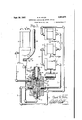
scription progresses, reference being had to the accompanying drawings in which L Figure l is a schematic generalyiew of my new and improved lubricating system, showing some of the parts in section;
Fig. 2 is a plan section View taken on the line 2 2 of Fig. 1; and
Fig. 3 is a schematic view showing a modified form of distributor an dicator in section.
Reference will now be made to the drawings in which like reference characters designate like parts throughout.
The numeral I represents a pump which is connected to and delivers lubricant under pressure to a lubricant flow-reversing and circuit-indicating device 2 which in turn is connected to both ends of. a circuit pipe-line or conduit 3 which y is equipped with a plurality of reversible feeders `4 provided with by-pass means as hereinafter described, and there is a return pipe 5 which returns lubricant from the now-reversing and circuit-indicating device to the .pump reservoir'.
- The pump I comprises a cylinder Shaving a cap 1 and a hollow head 8 having a circular bore 9 vscrewthreaded to receive a sleeve I 0, the inner end of which is screened by a suitable screen II secured thereto in' any suitable lmarmer. The .sleeve II) has a spider I2 which may be integral therewith and which is also perforated and screwthreaded in the center to receive a hollow screw Il having a head I4. A floating disk valve I5 assignments, to Trabon Engineering Corporation,l Cleveland, Ohio, a corporation Application March 1s, 1931, Vseriali No. 523,149
of Ohio (Cl. 184-7) l' slides on the screw I3 between the spider I2 and the head I4. l
The hollow head 8 ofthe pump has an extending supporting portion 8 receiving one end of the piston I6 the other end of the piston being received in the bore and sleeve. The piston IB has a central passage II which is counterbored as at I8, which receives the head I4 of the screw I3.
Radial passages I9 are drilled in the piston and permit the lubricant to flow from the central passage I'I into an annular chamber in the nozzle portion 8 of the hollow head 8 surrounding the reduced portion I6 of the piston It. The passage II is counterbored at the discharge end as at to accommodate a floating valve 2l and is screwthreaded to'receive a sleeve 22 acting as a seat for the valve.
The piston I6 is provided with a-rack 23 which registers with and is operated by a segment 24 mounted on a shaft 25 supported on the hollow yhead' and the segment is turned on the shaft by a handle 26.
such as the. packing gland 21 and the nut 28.
I have shown the outlet end of the portion 8' as screw threaded to t any suitable piping connection such as 29 which is suitably connected to a conduit 30 conveying the duid to the flow-reversing and circuit-indicating member 2 through a port 3| therein, although the pump may be tted directly to the port 3l.
-The port `3I communicates with two passageways 32 and 33. The passage 32 leads to a valve chamber 34. The passage 33 leads to a valve chamber 35.
A piston valve 36 having depressed portions 31, 38 and 39 providing valves 40, 4I, 42 and 43 is mounted to reciprocate in the valve chamber 34. The piston valve 36 is provided with an abutment member 44 and a cup leather piston 45 at one end and a similar abutment member 46 vand similar leather piston 41 at the other end.
The end of the valve chamber 34 in which abutment 44 is' mounted communicates with valve chamber through a passage 48 and the opposite end of the valve chamber 34 communicates with the valvechamber 35 through a passage 49.
A pistony valve 50 is mounted in the valve chamber 35 and is provided with depressedportions 5I, 52 andl53 providing valves 54, 55, 56 and 51. The valve 51 is provided with an extension V5'I which slides through a perforated nut and Asealing gland so as to indicate the movement -of the piston valve 50, as well as the movement of i The portion 8 of the hollow head 3 surround- Ain'g. the piston is sealed by any suitable means 5 the double headed piston 58 which actuates it. The p'wton 58 reciprocates in a cylinder 59 which has a passageway 60 connecting one end of the cylinder with a valve chamber 6| and a 5 second passageway 62- connecting the other end of the cylinder with said valve chamber 6|.
The valve chamber 6| has a dumb-bell piston type valve 6I adapted to reciprocate therein and communicates with an outlet passage 63 communicating with the return discharge portA 64 to which the pipe or conduit 5 is connected and said pipe 5 is connected to the pump reservoir in any suitable manner as at`65. l
One end of the valve chamber 6| communicates with the annular passage in valve chamber 34 surrounding reduced portion 31of the piston valve 36, between valves 40 and 4|, through a passage 66 and the other end of the valve chamber 6| communicates with the annular passage in valve chamber 34 surrounding reduced portion 39 of the piston valve- 36, between valves 42 and 43, through a passage 61.
Leading from the valve chamber 34 in such manner as to be blocked by the valve 40, when-in the position shown in the drawings, and so as to communicate with the annular passage surrounding the reduced portion 31 of thepiston valve 36 when it shifts, is a duct 68 leading to a return passage 69 which opens into the outlet passage 63. A similar duct 10 communicates between the valve chamber 34 and the passage 69,in such manner that it registers with the annular passage surrounding reduced portion 39 of the piston valve 36 when in the position shown 'and when the piston shifts, the duct 10 is closed by the valve 43.
Another passage 1| connects the valve chamber to the return passage 69 and said passage 1| always registers with the annular passage surrounding the reduced portion 5| of the piston valve 50 in the valve chamber. 35 between valves 54 and 55.4
A passage 12 connects the valve chamber 34 to one dual service port 13 which receives one end of the conduit 3 and said passage 12 is arranged in such manner that when the piston valve 36 is in the position shown it registers with the annular passage surrounding reduced portion 31 between valves 40 and 4| thus permitting communication with passage 66, and when the piston valve 36 is shifted, the passage 12 registers with the annular passage surrounding reduced portion 38 between valves 4| -and 42 thus receiving fluid entering. said annular passage through passage 32.
Another passage 14 connects the valve chamber 34 to the other dual-service port 14 which receives the other end of the conduit 3. The passage 14 is so arranged that when the piston valve 36 is in the position shown it registers with lthe annular passage in the valve chamber 34 surrounding reduced portion 38 between valves 4| and 42 and so receives 'fluid entering said annular lpassage through the passage 32, When the piston valve 36 is shifted the valve 42 prevents the passages 32 and 14 from communicating and .the passage 14 then communicates with the passage 61 around the annular passage surrounding re` duced portion 39 between galves 42 and 43.
A passageway 15 is drilled in the piston valve 50 l connecting the annular passages surrounding reduced portions 5| and 53.
When the pistonvalve 5461s in the position shown, the passageway 48 registers with the annular passage surrounding reduced' portion 52 S0 that fluid lentering said annular passage from passage 33 will pass into the passage 48 and shift the piston valve 36 in valve chamber 34 to the position shown and hold it there until th'e piston 58 again shifts when the passage 48 will register 5 with the annular passage surrounding reduced portion 5| of the piston valve 50 permitting lubricant to pass through passage 48 to passages 1I, 69, 63 and through port 64 and pipe 5 back to the pump reservoir.
In like manner the passage 49 when piston 50 is in position shown, registers with the annular passage surrounding reduced portion 53 of the piston valve 50', thus permitting fluid to a s from the valve chamber 34 at the end in which eather piston 41 is mounted through passage 49 intol the annular passage surrounding reduced portion 53 and through drilled passage 15 to the annular passage surrounding reduced portion 5I and thence back tothe reservoir' as above described, and when piston 50 shifts, passage 49 registers with the annular passage surrounding reduced portion 52 between valves 55 and 56 thus permitting fluid entering said annularv passage under pressure from passage 33 to flow into the valve chamber 34 at the side of cup leather 41 and abutment 46 causing valve 36 and all its parts to shift.
The automatic now-reversing aid circuit indieating device herein described and disclosed in Figs. 1 and 2 of the drawings, is not claimed per se in this application but it forms the subjectmatter of a divisionalapplication, Serial Number 86,111, flied June 19, 1936.
The pipe line or conduit 3 may have any number of feeders 4 of various sizes connected to any number of bearings or associated devices, and one feeder may be used for one or more such bearings or/associated devices by arrangingvsuitable branch pipes, or two feeders may be connected to one such bearing or associated device by merely providing a 'double valved connection.
Each feeder 4 is provided with two ports 80 and 8| connected to the pipe line or conduit 3 and a discharge port 83 connected to an associated device or to a bearing oito a, pipe-line or suitable conduit leading to a bearing or receiving device.
Each feeder is provided with a cylinder 84 having a iuid pressure operated piston 85 adapted to reciprocate therein.
Each port and 8| communicates with two cylindrical valve chambers and 86 through suitable passages. The valve chamber 86 has a duct 81 communicating with one end of the cylinder 84 and aduct 88 communicating with the other end of said cylinder, and the discharge port 83 communicates with the central portion of the valve chamber 86. A dumb-bell piston type valve 89 having two heads 90 and 9| is mounted in said valve chamber 86 in such manner that the annular passage lsurrounding the reduced portion between said valveheads 90 and 9| always connects Aone of the ducts 81 or 88 with discharge port 83A whenthe/valve is in either one of its. shifted posi.-
tions and at the same time opens the other duct 81 or 88 to the now of fluid from the conduit.
The valve chamber 85' has a similar dumbt bell piston type valve 92 having heads 93 and 94.
spective by-pass valve chamber, of which there 75 are two, designated 98 and 99, in each of which a slide valve of any ordinary type permitting fluid flow in one direction, is provided.
In the modification shown in Fig. 3; the flowreversing and circuitfindicating member 2 comprises 'a block provided with an inlet port 3| and two dual service ports 13 and 14' and a return discharge port 64 connected in like manner as the automatic device heretofore described.
The block is cylindrically bored and the bore is screw-threaded at each end, one endreceiving a hexed perforated screw plug which receives fluid from the pump, and serves as the inlet 3|, and the other end receives a packing gland through whichthe hollow extension |0| of a rotary valve plug |02 extends. The rotary valve |02 is mounted in the bore and the extension |0| is reduced thus providing a shoulder |03 against which the packing gland presses thereby holding,
the rotary valve plug in place. f,
The rotary valve plug is provided with a passage |04, one end of which is adapted to continuously register with the inlet port 3| and the other end of which is adapted to register with either port 13 or 14', depending on the position of thel valve. The rotary valve plug also has another passage |05, one end of which continuously registers with the central chamber ||0 in the hollow extension |0 l, and the other end is adapted to register with either one of the ports 13 or 14', always the one not registeringat the vsaline time with passage |84. Mounted in the central chamber ||0, in the extension |0| so as to close it. is a spring pressed piston valve assemblyI |06 which is also adapted to normally close one end of the passage and this valve has an extending stem |01 on which there is a second piston valve |08 which is adapted to extend into one end of the passage |05. The valve |08 has a tapered portion adapted to make entrance to passage |05 easy after it has been forced out thereof by the flow of iluid returning from the pipe-line circuit. The extension |0| is closed by a perforated cap through which a rod or other indicating member I|2 slides and the cap also serves as an abutment for the spring which closes the valve.
The central passage ||0 is always in communication with the return discharge port 64 by reason of the fact that the bore of the body member 2 is countersunk as at 3 thus providing an annular passage around the valve plug which communicates with 'said port G4 and radial passages |'4 are drilled inthe valve plug to communicate between the central passage ||0 and the said annular passage in the bore.
The valve plug is manually operated-by means of a handle ||5 secured to the extension |0|.
The numeral I6 represents a bearing or any other suitable receptacle, of which as heretofore described, there may be any number, and4 usually one branch pipe leads from each feeder to each bearing or receptacle.
Assuming that my system the automatic l flow-reverser as illustrated in Figs. l and 2 is filled with lubricant the operation is as follows: The operator oscillates the handle 26, thereby l oscillating the segment 24 and reciprocating the pistonl I6 by -means of the rack 23, so that as the piston and around the floating disk'valve I5 is filled with lubricant by reason of suction and gravity and said lubricant is free of dirt and grit by reason of passing through the screen 0neach upward stroke of the piston some of the lubricant trapped between the valve I5 and the enlarged head of the piston is forced out through the small passage in the screw |3 and back through the screen into the reservoir of the pump thus cleansing the screen, and as the pas` sage through the screw is smaller than the passage H, themajority of said lubricant is forced through the passage |1, forcing the slide Avalve 2| to its seat on the sleeve 22 thereby the passage |1 to the radial passages |9 t ough which said lubricant passes to the annular pas-- sage around the reduced portion I6 of the piston I8 and below the moving parts of the piston.
As the lubricant is pumped thro-ugh the conduit 30 it enters the automatic flow-reversing 'and circuit-indicating member 2 through the port 3| Where part of it will pass through passage 33 into the annular chamber in valve chamber 35 surrounding reduced portion 52 of the piston valve 50 between valves 55 and 56 from whence it will pass into passage 48 and be conveyed into valve chamber34 at the end adjacent abutment 44 of the piston valve 36 and acting o-n `the leatherpiston 45, where such is used'or on the piston valve itself, will force the same to the position shown in Figure 1 and hold it there whilethe lubricant entering passage 32 is transmitted throughout the circuit in one direction. y In order that the .valve 36 may move however, lubricant in the valve chamber 34 at ,the end in which abutment 46 is ening located, must be displaced, and this therefore is into the annular passage in the valve chamber 34 surrounding reduced portion 38 of the piston valve 36 between valves 4| and 42 from whence it will pass into passage 14 and thence through dualservice port 14 to one end of the pipe line or vconduit 3 passing to the first progressive measuring feeder 4 and entering the same through port 8| at which time the ports will be in the position shown in the feeder illustrated in section. The
- flow of the lubricant will then force both dumbbell type piston valves 89 and 92 to slide to their opposite positions thus blocking the direct flow of lubricant from the port 8| through valve, chamber 85 at the same time opening the duct 88 to the flow of lubricant from the port 8| through valve chamber 86, thus passing into the cylinder 84 and forcing the piston 85 to discharge lubricant on the other side through the duct 81 into the valve chamber 86 between valve heads 90 and 9| and thence through the discharge port '83 to the branch pipe leading to the bearing and thence to the bearing. After the piston has been forced from the position illustrated to its opposite positionA lubricant entering-the feeder through port 8| may then pass through the cylinder and through duct 95 into the valve chamber 85 in the annular passage surrounding the reduced portion of the dumb-bell type pistonv valve 82' between valve heads 83 and 94 from whence it will pass through duct 96 to the valve chamber 98 and through the valved outlet thereof to the passage leading to port 80 through which it will pass to the conduit and then on to the next feeder, and so on through all .feeders in the circuit and thence reenter the automatic flowreverser and circuit-indicating member 2 through dual-service port 13 into and through passage' 12 and into the annular passage in valve chamber 34 surrounding the reduced portion 31 of the piston valve 36 between valves 40 and 4| passing thereout through passage 66 into the valve chamber 6| where it encounters' one head of the dumbbell piston valve 6|. The flow moves this 'valve from the position shown in Fig. 2 to its opposite position, which permits the lubricant to pass through passage 62 into the cylinder 59 forcing it to shift the piston 58 from the position shown to its opposite position. Said shifting of the piston 58 shifts the piston valve 50 and all its parts and causes the indicator 51 to project a ,considerable distance through the packing gland which seals the valve chamber 35 to the valve 51 and extension 51.
In order that the valve 6| may shift from the position shown, lubricant in the valve chamber 6| on the other side of the valve must be displaced, so it is free to pass through passage 61 and into the valve chamber 34 betweenvalves 42 and 43 and thence through passages 10, 69, 63, port 64, pipe 5 and port 65 back to the reservoir.
Also in order that the piston 58 may shift from the position shown, the lubricant on the other side thereof passes out through passage 60 and into valve chamber 6| between the heads of the valve 6| and thence out through passage 63, port 64, pipe 5 and port 65 back to the reservoir. i'
When the piston 58 shifts thevalve 50, this causes the passage 33 to communicate, through the annular passage invalve chamber 35 surrounding reduced portion 52 of piston valve 50, with passage 49, thus causing the valve 36 and all its parts to shift, and lubricant entering passage 32 will now be directed throughvalve chamber 34 and out through passage 12 and port'13 and so on in the reverse manner,
With the hand valve as illustrated in Fign,
'the operator pumps until the indicator I I2 moves up and down on-.each'stroke of thepump and then he shifts the valve andi` pumps again until the indicator moves, and he then knows that `each bearing connected to the rcuit has been lubricatedtwice. If he neg ects to shift the valve the indicator Will continueto move and he will simply l be pumping lubricant through the by-passes inthe feeders and .back into thereservoir.
' When the lubricant returns through passage |05 it moves the valve |08 to rise out of said passage |05.and'as the piston valve |05 seals the passage |,|0, Ythe lubricant passes throughpassages |'|4, ||3 to port 64 and thencev'through the pipe 5 back to the reservoir. The spring returns the valves |06 and v|08 to their normal seats when pressure is relieved, and v,no pressure can be placed on the spring until each feeder in the circuit has satisfactorily discharged its measured quantity of lubricant to its associated bearing.
` AMany equivalent means will -become apparent understood that where the wordlubrica'nt is used in the claims, any other fluid such as water; gas and the like or any plastic material may be substituted and that any receptacle may be substi'- l tuted for a bearing. vWhat I claim isz- 1. The combination of a plurality of bearings'y to be lubricated, a series of feeders, one adjacent each of said bearings, a pipe line connecting each of said feeders and adapted at each end to receive lubricant under pressure, each of said feeders, supplying a measured quantity of lubricant to its associated bearing and uncovering a passage to the continuation of the pipe line when the lubricant is forced therethrough in either direction of flow;
2. In combination, a pump, a flow-reversing member connected thereto, a conduit leading from said member and returning thereto, and a lubricant discharging feeder connected to said conduit. said feeder having means for discharging a quantity of lubricant to a bearing when the lubricant is moved through the conduit in either direction of flow.
3. In combination, a pump, a flow-reversing and circuit-indicating member connected thereto, a conduit leading from said member and returning thereto, and a lubricant discharging feeder connected to said conduit, said feeder having means for discharging a quantity of lubricant to a bearing when the lubricant is moved through the conduit in/either direction of flow.
4. 'In combination, a pump, a lubricant fitting connected thereto for-receiving lubricant under pressure and having two discharge and return ports and means for alternately directing the lumoved through the conduit in either direction of flow, and means on the fitting for indicating when the means for alternately directing the lubricant out of `one discharge port and then out of the other has been shifted.
5. The combination with a pump of a flowreversing member, a conduit leading therefrom and returning thereto, and a lubricant-discharging feeder connected to said conduit provided with means for flrst discharging a quantity of lubricant to a bearing and for then uncovering a passage permitting lubricant under pressure to flow on through the conduit and back to the flowreversing member. 6. 'I'he combination with a pump of a circuitindicating and how-reversing member, a conduit leading therefromand returning thereto, and a lubricant-discharging feeder connected to said conduit provided with means for first discharging a quantity of lubricant to a bearing and for then uncovering a passage permitting .lubricant under pressure to. flow onthrough the conduit and back to the circuit-indicatingl and flowreversing member.
'7. 'I'he combination with a pump of a lubricant fitting connected thereto for receiving lubricant under pressure, a conduit leading from said fitting and returning thereto, a-lubricant discharging feeder connected to said conduit provided with means for rst discharging a quantity of lubricant to a bearing and forthen uncovering a Ipassage permittingjubricant under pressure to ow on through the conduit back to the lubricant fitting, and means in said fitting for reversing the flow through said conduit and means operated by said iiow reversing means for'indicating that the system is working satisfactorily.
' 8. In combination, a pump, a lubricant fitting connected thereto for receiving lubricant therefrom under pressure, said fitting having two discharge ports and also having means for reversing the discharge of lubricant therefrom, a conduit leading from o-ne of the discharge ports of said ttingand returning \to the other, a plurality of feeders connected to said conduit through which lubricant is discharged into bearings associated therewith, and bypass means in said feeders permitting flow oflubricant under pressure from said iitting and through said conduit and feeders and back to said. iitting, and means for indicating whether or not the conduit is broken. h
9. The combination of a plurality of bearings to be lubricated, a seriesl of measuring devices one adjacent each of said bearings, a pipe line connecting said devices and extending from each end oi the series, a lubricant fitting for receiving lubricant under pressure and connected to the extending extremitiesof the pipe line, each of said devices supplying a measured quantity of lubricant to its associated bearing and uncovering a passage to the pipe line leading to the next de- -vice of the series and back to the lubricant fitting,
and means for directing lubricant through said pipe line and measuring devices in either direction of flow.
10. The combination of a plurality of bearings to be lubricated, a series of measuring devices one adjacent each of said bearings, a pipe line connecting said devices and extending from each end of the series, a lubricant fitting for receiving lubricant under pressure and connected to the extending extremities of the pipe line, each of said.devices supplying a measured quantity of lubricant to its associated bearing and uncovering a passage to the pipe line leading to the next device of the series and back to the lubricant tting, means for indicating when the lubricant has made a complete circuit from the lubricant f1tting and through the pipe line and measuring devices and back tothe lubricant fitting, and means for directing lubricant through said pipe line and measuring devices in either directionof flow.
11. The combination with a pump, of a lubricant conduit extending therefrom and returning thereto and provided `with a plurality of passageways adapted for connection to a plurality of bearings, means for reversing the flow through the conduit, means within the conduit for stopping the flow through-theconduit when a bearing to which it leads is clogged, said means also supplying a quantity of lubricant to that bearing when it is not clogged and adapted to permit the lubricant to iiow on through theconduit after such measured quantity has been supplied to said bearing.
,f 12. The combination with a pump, of a lubricant conduit extending therefrom and returning thereto and provided with a plurality of passageways adapted for connection to a plurality of bearings, means for indicating when the lubricant has made a complete circuit through said 'conduit and for reversing the iiow through the conduit, means within the conduit for stopping the flow through the conduit when a bearing to which it leads is clogged, said means also supplying a quantity of lubricant to that bearing when it is not clogged and adapted to permit the lubricant'to flow on through the conduitafter' such measured quantity has 'been supplied to said bearing.
13. The combination with a pump, of a lubricant conduit extending therefrom and returning thereto and provided with a plurality of passageways adapted for connection to a plurality of bearings, automatic means for reversing the iiow through the conduit, means within the lconduit for stopping flow through the conduit when a bearing to which it leads is clogged, said means also supplying a quantity of lubricant to that bearing when it is not clogged and adapted to permit the lubricant to flow on through the conduit after such measured quantity has been supplied to the bearing.
14. The combination with a pump of a lubricant conduit extending therefrom and returning thereto and provided with a plurality of passageways adapted for connection to a plurality of bearings, automatic means for indicating when the lubricant has made a complete circuit through said conduit and for reversing the ow through the conduit, means within the conduit for stopping the flow through the conduit when a bearing to which it leads is clogged, said means also supplying a quantity of lubricant to that bearing when it is not clogged and adapted to permit the lubricant to ow on through the conduit after such measured quantity has been supplied to the bearing. 15. The combination with a pump, of a lubricant conduit extending therefrom and returnl ing thereto and provided with a plurality of passageways adapted for connection to a plurality of bearings, means for indicating when the lubricant has made a complete circuit through said conduit and hand operated means for reversingI the iiow through the conduit, means within the conduit for stopping the iiow through the conduit when a bearing to which it leads is clogged, said means also supplying a quantity of lubricant-to that bearing when it is not clogged and adapted to permit thek lubricant to flow on through the conduit after such measured quantity has been supplied to that bearing.
16. A lubricating system comprising a singlepipe circuit connected to a flow-reversing member receiving lubricant under pressure, feeders arranged in series in said single-pipe circuit and forming part thereof, bearings connected to said feeders, said feeders having means for discharging a measured quantity of vlubricant as a result of each operation, and an indicator for -showing when the lubricant has passed through the enof a measured quantity of lubricant to the connected bearings is insured upon each reversal of flow of the lubricant, a tell-tale indicator mounted o`n said flow-reversing member that shows whether or not all connected bearings have been lubricated, said flow-reversing member l'functioning normally in changing direction of ow when the last feeder of the piping circuit has been served.
18. The combination of a plurality of bearings to be lubricated and a single-*pipe flow-reversing lubricating system comprising a single-pipe main lubricant-distributing circuit, means for supplying lubricant thereto under pressure, means for reversing the direction of flow of lubricant in said circuit, lubricant feeders arranged in series in said main circuit and forming part thereof, branch pipes connecting said feeders to the bearings to be lubricated, means within the feeders to insure discharge therefrom to the bearings connected therewith of a measured quantity of lubricant upon each reversal of the direction of flow of lubricant within said main circuit, the alternating ow and returnA ends of which are connected to a :dow-reversing member containing means for indicating obstruction. to flow of lubricant to any one of the bearings.
19. The combination of a plurality of bearings to be lubricated, a plurality of feeders arranged in series one adjacent each of said bearings, a conduit connected to each of said feeders at 'each end thereof, each of said feeders having an outlet passage communicating with its respective bearing and having a plurality of. ports connected tov said conduit for delivering lubricant thereto and therefrom under pressure, and -having pressure operated means for delivering to a bearing a predetermined .quantity of lubricant entering each feeder through any of the said plurality of ports, and having means for directing lubricant under pressure to owV through said device to another of said plurality of ports after forcing lubricant into' the bearing to which,
it is connected, each of said feeders being adapted to function when the lubricant is forced therethrough from either direction of flow in the conduit, and means in each end of the conduit for receiving lubricant under pressure.
20. Apparatus of the class described comprising a body having an inlet port for receiving lubricant under pressure and a pair of dualservice ports for discharging lubricant to and.
for receiving lubricant from aA lubricant circuit and means for alternately directing lubricant from said body to the circuit first in one direction of flow and thenin the other direction of flow. A
21. Apparatus of the class described comprising a body having an inlet port for receiving lubricant under pressure and a pair of vdual-service ports for discharging lubricant to and for receiving lubricant from a lubricant circuit, means for alternately directing lubricant from said body to the circuit ilrst in one direction of flow and then in the other direction of ow, and means for indicating when lubricant has been received from the circuit.
22. Apparatus of the class described comprising a body having an inlet port for receiving lubricant under pressure and a pair of dualservice ports for discharging lubricant to and for receiving lubricant from a lubricant circuit, means for 'alternately directing lubricant from said body to the circuit in one direction of ow and then in the other, and an indicator operated by the pressure of the returning lubricant for showing when lubricant discharged to the circuit has made a complete circuit therethrough.
23. Av flow-reversing valve comprising a body member having an inlet port, two dual-service ports, a. return discharge port and a cylindrical bore, a Valve member mounted in .said bore, a
passage in said valve member adapted to connect the inlet port with either one of said dual service ports, a second passage *n said Valve member adapted to connect the return discharge port with either of the dual service ports, said passages being so arranged that when one Adualservice port is connected with the inletport the other is connected to the return discharge port and manually operable means for shifting said valve.
24. A flow-reversing device comprising a body member having an inlet port, a pair of dualservice ports adapted for connection to the ends of a circuit and a return discharge port, valve means adapted to be alternated to connect the inlet port `first to one and then te the .other of the dual-service ports while simultaneously connecting the return discharge port rst with one and then with the other `of the dual-service ports whereby, when the inlet port V is connected to one dual-service port, the return discharge port is connected to the other dual. service port.
25.y A flow-reversing device comprising a body' member having an inlet port, a pair of dualservice ports adapted for connection to the ends 'of a circuit, a return. discharge port, valve means adapted to be alternated to connect the inlet port Y `first to one and then to the other of the dualservice ports while simultaneously connecting the return discharge port first with one and then with the other of the dual-service ports whereby, when the inlet port is connected to one dualservice port, the return discharge port is connected to the other dual service port and an indicating member operable by the return pressure of the fluid for indicating when i'luid is returning through the device.
26. In combination, a lubricant reservoir, a pump connected thereto adapted to pump lubricant therefrom, a flow-reversing member connected to said pump, a conduit leading from said member and returning thereto, a lubricant discharging feeder connected to said conduit, said feeder having means for discharging a quantity of lubricant .to a bearing when the lubricant is moved through the conduit in either direction of flow, saidflow-reversing member being adapted tov discharge the returning lubricant into said E reservoir.
27. In combination, a lubricant reservoir, a pump connected thereto and adapted to pump lubricant therefrom, a now-reversing member connected to said pump and having another connection direct to said reservoir, a conduit leading from said member arid returning thereto, a lubricant discharging feeder connected to said conduit, said feeder having means for discharging a quantity of lubricant to a bearing when the lubricant is moved through the conduit in either direction of flow, said flow-reversing member being adapted to discharge the returning lubricant into Y said reservoir.
28. ln combination, a pump, an automatically operated flow-reversing member connected therewhen the 'lubricant is moved through the conduit in either-direction of ow. v I
29. In combinations. pump, a now-reversing member connected thereto. comprising a body having an inlet and a pair of vdual service ports and an exhaust, a primary valve means adapted to alternately connect the inlet with the respective dual service ports, secondary valve means adapted to control-said primary valve means by directing pressure thereto from said inlet and connecting means between said dual service ports and the secondary valve means, whereby the latter is rendered operable, a conduit leading from one of the dual service ports of said flow-reversing member and returning to the other, and a lubricant' discharging feeder connected to said conduit, said feeder having means for discharging a quantity of lubricant to a bearing when the lubricant is moved through the conduit in either direction of flow.
30. In combination, a pump, an automatically operated flow-reversing and circuit-indicating member connected thereto and receiving lubricant therefrom, a conduit leading from said member and returning thereto, and a lubricant discharging feeder connected to said conduit, said feeder having means for discharging a quantity of lubricant to a bearing when the lubricant is moved through the conduit in either direction of 3l. In combination, a pump, a flow-reversing and circuit-indicating member connected thereto and receiving lubricant therefrom, said member having a moveable part controlled by the return flow of lubricant therethrough,a conduit leading from said member and returning thereto, and a lubricant discharging feeder connected to said conduit, said feeder having means for discharging a quantity of lubricant to a bearing when the lubricant is moved through the conduit in either direction of flow.
32. In combination, a pump, a lubricant fitting connected theretohaving an inlet port for receiving lubricant under pressure and having two discharge and return ports and having automatically operated--means controlled by the return flow of lubricant under pressure for alternately directing the lubricant out of one of said ports and then Aout of the other,'a conduit leading from one of. the discharge and return ports of said fitting and returning to the other of said ports, alubricant ldischarging feeder connected to said conduit, said feeder having means for discharging a quantityof lubricant to a bearing when the lubricant is moved through the conduit in either direction of fiow, and-means on the fitting for indicating when the means for alternately directing the lubricant out of one discharge and return port and then out of the other has been shifted.
33. In combination, a pump, a lubricant ttingv connected thereto forrreceiving lubricant under pressure and having two discharge and return ports and having an automatically operated owreversing member controlled by the return flow of lubricant under pressure forl alternatelyidirecting the lubricant out of one of said ports and then out of the other, a conduit leading from one of the discharge and return ports of said fitting and returning to the other of said ports, a lubricant discharging feeder connected to said conduit, said feeder having means for discharging a quantity of lubricant to a bearing when the lubricant is moved through the conduit in either direction of ow, and'means on the tting for indicating when the means for alternately directing, the lubricant out of one discharge and return port and then out of the other has been shifted.
34. In combination, a pump, a lubricant fitting connected thereto for receiving lubricant under pressure and having two discharge and return ports and means for alternately directing the lubricant out of one of said ports and then out of the other, a conduit leading from one of the discharge and return ports of said fitting and returning to the other of said ports, a lubricant discharging feeder connected to said conduit, said feeder having means for discharging a quantity of lubricant to a bearing when the lubricant is moved through the conduit in either direction of iiow, and means on the fitting controlled by the pressure of lubricant returning thereto for indicating when the means for alternately directing the lubricant out of one discharge port and then out of the other has been shifted, said means including a moveable member -controlled by flow of lubricant through said fitting.
'35. The combination with a pump of an automatically operated flow-reversing member connected thereto and receiving lubricant therefrom,
a conduit leading from said member and returning thereto, and a lubricant-discharging feeder connected to said conduit provided with means for first discharging a quantity of lubricant to a bearing and for then uncovering a passage permitting lubricant under pressure to flow on through the conduit and back to the i flowreversing member.
36. The combination with a pump of an automatically operated circuit-indicating and 'flowreversing member connected thereto and receiving lubricant therefrom, a conduit leading from said member and returning thereto, and a lubricant-discharging feeder connected to said conduit provided with means for first discharging a quantity of lubricant to a bearing and for then uncovering a passage permitting lubricant under pressure to ow on through the conduit and back to the circuit-indicating and flow-reversing member.
37. The combination with a pump of a circuitindicating and flow-reversing member connected thereto and receiving lubricant therefrom, said member including a moveable part controlled by flow of lubricant therethrough, a conduit leading from said member and returning thereto, and a lubricant-discharging feeder connected to said conduit provided with' means for rst discharging a quantity of lubricant to a bearing and for y then uncovering a passage permitting lubricant under pressure to flow on through the conduit and back to the circuit-indicating and flowreversing member.-
38. The combination with a pump of a lubricantiitting connected thereto for receiving lubricant under pressure, a conduit leading from said fitting and returning thereto, a lubricant discharging feeder connected to said conduit provided With means for rst discharging a 'quantity of lubricant to a Abearing and for-then uncovering a passage permitting lubricant under pressure to ow on through the conduit back to the lubricant tting, means in said fitting for reversing the flow through said conduit and means, comprising a moveable member operated by said flow-reversing means, for indicating that the systern is working satisfactorily.
39. Ihe combination With a pump of a lubricant fitting connected thereto for receiving lubricant under pressure, a conduit leading from said fitting and returning thereto, a lubricant discharging feeder connected to said conduit provided with means for first discharging a quantity sure to fioW on through the conduit' back to the lubricant fitting, and means in said fitting for reversing the fiow through said conduit, said flow-reversing means including a moveable member that is automatically moved on 4each completion of i'low of lubricant through said pipeline from said fitting and back thereto and moveable indicating means operated by the moveable member of said flow-reversing means for indiby-pass means in said feeders permitting flow of lubricant from said fitting and through said conduit and feeders and back to said fitting in either direction of flow, andmeans including a member moveable by pressure of the return flow of lubricant for indicating whether or not the conduit is broken. A
41. In combination, a pump, a lubricant fitting connected thereto for receiving lubricant therefrom under pressure, said tting having two discharge ports and also having automatically operated means for alternately reversing the discharge of lubricant therefrom, 'a conduit leading from one of the discharge ports of said fitting and returning to the other, a plurality of feeders connected to said conduit through which lubricant is discharged intovbearings associated therewith, and by-pass means in said feeders permitting flow of lubricant under pressure from said fitting and through said conduit and feeders and back to said fitting in either direction of fiow, and means for indicating whether or not the conduit is broken.
42. In combination, a pump, a lubricant fitting connected'thereto for receiving lubricant therefrom under pressure,- said fitting having two discharge ports and also having automatically operated means for alternately reversing the discharge of lubricant therefrom, a conduit leading from one of the discharge ports of said fitting and returning to the other, a plurality of feeders connected to said conduit through which lubricant is discharged into bearings associated therewith, and by-pass means in said feeders permitting flow of lubricant under pressure from said fitting and through said conduit and feeders and back to said fitting in either direction of ilow, and a moveable member mounted on said fitting actuated by said flow-reversing means for indicating whether or not the conduit-is broken.
to be lubricated, a series of measuring devices one /adjacent each of said bearings, a pipe-line connecting said devices and extendingv from each end of the series, a lubrican'tl fitting for receiving lubricant under pressure and connected to the V. extending extremities of the pipe-line, each of said devices supplying a measured quantity of tting when lubricant flows therethrough in 4'either direction of flow, and automatically operated means for directing lubricant through said pipe-line Vand measuring devices in alternate directions of fioW.
44. The combination of a plurality of bearings to be lubricated, a series of measuring devices one adiacent each of said bearings, a pipe-line connecting said devices and extending from each end of the series, a lubricant tting for receiving lubricant under pressure and connected to the extending extremities of the pipe-line, each of said devices supplying a measured quantity of lubricant to its associated bearing andl uncovering a passage to the pipe line leading to the next device of the series and back to the lubricant fitting when lubricant ows therethrough in either direction of flow, means for directing lubricant through said pipe-line and measuring devices in either direction of fiow, and a moveable circuit indicating member operable .by the pressure of lubricant on completion or" a circuit through the pipe-line.
45. The combination of a plurality of bearings to be lubricated, a series of measuring devices one adjacent each oi said bearings, a pipe-line connecting said devices and extending from each end of the series, a lubricant fitting for receiving lubricant under pressure and connected to the extending extremities'of the pipe-line, each oi said devices supplying a measured quantity of lubricant to its associated bearing and uncovering a passage to the pipe-line leading to the next device of the series and back to the lubricant fitting, indicating means responsive to the low of lubricant through the fitting for indicating when the lubricant has made a complete circuit from the lubricant fitting and through the pipeline and measuring devices and back to the lubricant fitting, and means for directing lubricant through said pipe-line and measuring devices 'in either direction of iioW. 4
46. The combination with a pu'mp, of a lubricant conduit extending therefrom and returning thereto and provided with a plurality of passage\$ Ways adapted for connection to a plurality of bearings, indicating means including a member moveable in response to the return flow of lubricant under pressure for indicating when the lubricant has made a complete circuit through said conduit, hand operated means for reversing the flow through the conduit, means within the conduit for stopping the flow through the conduit when a bearing to which it leads is clogged, said means also supplying a quantity of lubricant to that bearing when it is not clogged and adapted to permit the lubricant to flow on through the conduit after such measured quantity has been i supplied to that bearing.
47. A lubricant system comprising a single-pipe circuit having its 'respective ends connected to a How-reversing member receiving lubricant under pressure, feeders arranged in series in said singlepipe circuit and forming part thereof, bearings connected to said feeders, said feeders having means for discharging a measured quantity of lubricant as a result of each operation, and a moveable indicator for showing when the lubricant has passed through the entire. circuit.
48. A lubricating system for supplying lubricant to a plurality of bearings, comprising a reversiblefiow single-pipe circuit, feeders arranged in series in said single-pipe circuit and connected to said bearings by relatively short branch pipes and receiving from said single-pipe Acircuit', lubricant flowing under pressure firstin one and then in the opposite direction, a How-reversing member connected to the ends of said single-pipe circuit lill for receiving lubricant under pressurefor distribution through the single-pipe circuit to the respective feeders and thence to bearings, said feeders embodying means whereby discharge -of a measured quantity oi lubricant to the connected bearings is insured upon each reversal oi ilow oi the lubricant, a moveable tell-tale indicator controlled by the return flow of lubricant under presi `sure in said now-reversing member and mounted thereon that shows whether. orl not all connected bearings have been lubricated, said :dow-reversing member functioning normally in changing vdirection oi ilow when the lastfeeder oi' the piping circuit has been served.
, 49. The combination of a plurality of bearings to be lubricated and a single-pipe now-reversing lubricating system comprising a single-pipe main lubricant-distributing circuit means for. 4supplyl ing lubricant'y thereto under pressure: lubricant feeders arranged in series in said main circuit and forming partthereof, branch pipes connecting said feeders to the bearings to be lubricated,-
means within the -reeders to insure discharge therefrom to the bearings connected therewith of V a measured quantity of lubricant upon each reunder pressure for indicating the completion of v valve means iorleontrolling said pressure respon- 50. The combination of a plurality of bearings 35 a flow 'of lubricant through the circuit.
to be lubricated. and a single-pipe dow-reversing lubricating system comprising a single-pipe main lubricant-distributing circuit, means for supplying lubricant thereto'under pressure, means forv reversing the direction of ilow of lubricant in said circuit, said means being, operable automatically upon return il'ow !.lubrlcant thereto from the circuit, lubricant feeders arranged in series in said main circuit and forming part thereof,`
branch pipes connecting said feeders tothe bearings tobe lubricated, and means within the feeders to insure discharge thereiromto the bearingsl connected therewith oi a measured quantity of lubricant upon each reversal oi' the .direction'of flow oi' lubricant within said main circuit, the ends of said circuit being connected to t e cans for reversing the direction of'ilew of lubricant in said circuit; said reversing means including means ing pressure thereto from said inlet and from the primary valve ,means to said exhaust, a conduit having the ends thereoi' connected to said outlets and through which pressure duid is adapted to be returned to said body by being :forced through theY conduit alternately in opposite direndered effective by actuation oi' said primary sive means. v
. DAVID R. HILLIS.
.to control said primary valve meansby direct' l .rections, means responsive to pressure fluid being returned to said body-through said conduit for ,actuating said secondary valve, and valve means
Priority Applications (1)
| Application Number | Priority Date | Filing Date | Title |
|---|---|---|---|
| US523149A US2094271A (en) | 1931-03-16 | 1931-03-16 | Reversible lubricating feeder system |
Applications Claiming Priority (1)
| Application Number | Priority Date | Filing Date | Title |
|---|---|---|---|
| US523149A US2094271A (en) | 1931-03-16 | 1931-03-16 | Reversible lubricating feeder system |
Publications (1)
| Publication Number | Publication Date |
|---|---|
| US2094271A true US2094271A (en) | 1937-09-28 |
Family
ID=24083848
Family Applications (1)
| Application Number | Title | Priority Date | Filing Date |
|---|---|---|---|
| US523149A Expired - Lifetime US2094271A (en) | 1931-03-16 | 1931-03-16 | Reversible lubricating feeder system |
Country Status (1)
| Country | Link |
|---|---|
| US (1) | US2094271A (en) |
Cited By (3)
| Publication number | Priority date | Publication date | Assignee | Title |
|---|---|---|---|---|
| DE1028400B (en) * | 1953-04-15 | 1958-04-17 | Alfred R Schlosshauer | Central lubrication system, consisting of a central pump and any number of distributors in series to a ring line that goes out from the central pump and is connected to it |
| US2856023A (en) * | 1956-02-01 | 1958-10-14 | Farval Corp | Progressive metering valve and fluid pressure system utilizing same |
| DE1450240B1 (en) * | 1963-04-12 | 1969-12-11 | Daikin Ind Ltd | Reversing valve for single-line centralized lubrication systems |
-
1931
- 1931-03-16 US US523149A patent/US2094271A/en not_active Expired - Lifetime
Cited By (3)
| Publication number | Priority date | Publication date | Assignee | Title |
|---|---|---|---|---|
| DE1028400B (en) * | 1953-04-15 | 1958-04-17 | Alfred R Schlosshauer | Central lubrication system, consisting of a central pump and any number of distributors in series to a ring line that goes out from the central pump and is connected to it |
| US2856023A (en) * | 1956-02-01 | 1958-10-14 | Farval Corp | Progressive metering valve and fluid pressure system utilizing same |
| DE1450240B1 (en) * | 1963-04-12 | 1969-12-11 | Daikin Ind Ltd | Reversing valve for single-line centralized lubrication systems |
Similar Documents
| Publication | Publication Date | Title |
|---|---|---|
| US1990524A (en) | Lubricating apparatus | |
| KR20090016630A (en) | Valve type oiler | |
| US2667236A (en) | Lubricant measuring spray means | |
| US3038557A (en) | Positive proportioning, open-line-indicating lubricating system | |
| US2094271A (en) | Reversible lubricating feeder system | |
| US1870188A (en) | Device for measuring, regulating, and metering supply or distribution of fluids | |
| US2948222A (en) | Pump | |
| US2146424A (en) | Feeding device for lubricants or the like | |
| US2855069A (en) | Lubricating system and flow reversing valve | |
| US2856023A (en) | Progressive metering valve and fluid pressure system utilizing same | |
| US2105490A (en) | Lubricator | |
| US2699842A (en) | Measuring valve | |
| USRE21160E (en) | Reversffil | |
| US764886A (en) | Lubricator. | |
| US2380608A (en) | Control valve | |
| US2428035A (en) | Hydraulically controlled dispensing pump | |
| US2170327A (en) | Combined alternating pump and control valve | |
| US2115637A (en) | Fluid distributing device | |
| US2327025A (en) | Resistance unit | |
| US1880854A (en) | Lubricating system and apparatus | |
| US2240158A (en) | Fluid distributing system | |
| US2029198A (en) | Lubricant metering device | |
| US2005166A (en) | Lubrication system | |
| US3516517A (en) | Air lubrication system | |
| US2346801A (en) | Fluid dosing device |