US2087830A - Thread guide for straight knitting machines - Google Patents
Thread guide for straight knitting machines Download PDFInfo
- Publication number
- US2087830A US2087830A US746607A US74660734A US2087830A US 2087830 A US2087830 A US 2087830A US 746607 A US746607 A US 746607A US 74660734 A US74660734 A US 74660734A US 2087830 A US2087830 A US 2087830A
- Authority
- US
- United States
- Prior art keywords
- thread guide
- sinkers
- thread
- members
- guide
- Prior art date
- Legal status (The legal status is an assumption and is not a legal conclusion. Google has not performed a legal analysis and makes no representation as to the accuracy of the status listed.)
- Expired - Lifetime
Links
Images

Classifications
-
- D—TEXTILES; PAPER
- D04—BRAIDING; LACE-MAKING; KNITTING; TRIMMINGS; NON-WOVEN FABRICS
- D04B—KNITTING
- D04B15/00—Details of, or auxiliary devices incorporated in, weft knitting machines, restricted to machines of this kind
- D04B15/38—Devices for supplying, feeding, or guiding threads to needles
- D04B15/54—Thread guides
- D04B15/64—Thread guides for straight-bar knitting machines
Definitions
- This invention relates to thread carriers for knitting machines. and particularly those used on fiat machines of the type commonly employed in the manufacture of full fashioned hosiery.
- the object ofthis invention is to provide a thread guide which will not injure the sinkers of the knitting machine nor will itself become in ured as a result of the motion for efiecting needle-traversing movement of thethread guide getting out of time with the motion which projects the sinkers of the machine outwardly across the path of the thread guide, 1. e. in cases where the sinkers are projected in advance of the thread guide instead of behind the thread guide as the thread guide is moved in opposite directions alternately in a plane parallel to and intermediate v that of the front ends of the sinkers and the plane of the bank of needles with which the sinkers cooperate.
- This invention is particularly adaptable for use with the recently developed three-carrier knitting process, adapted for eliminating rings in sheer hosiery, wherein each of the three individual thread carriers employed makes but a single needle-traversing movement at any one time, which requires the disconnection of each carrier rod from the Coulier motion of the machine or a friction box driven by said motion after the thread guide has laid thread for one course of stitches and the reconnection of a different carrier rod .to the mechanism which eiiects the needle-traversing movements of the thread guides before a thread is laid to the needles for the formation of a succeeding course of stitches.
- the thread guide constituting the subject matter of the present invention is so constructed that, in event of the lower endof the thread guide contacting with any one of the sinkers in the course of travel of the thread guide across the series of sinkers, such contact will result in the lower end of the thread guide being-moved 1 ;t aliy to an inoperative-position above the tops 01' the sinkers without damage being done to either the thread guide or the sinkers.
- Alternating with the sinkers is a series of dividers which are of substantially the same construction as the sinkers and which are projected outwardly between the sinkers, after the sinkers have been successively projected, in order to divide the thread equally around and between each and all of the needles then operating in any single knitting head of the machine.
- the sinkers and dividers are operated en masse by .the catch bar of the machine and if for any reason one or more of the sinkers ordividers shall fail to be retracted by the catch bar and be left in a projected position until the thread guide makes its next needle-traversing movement the thread guide will upon engaging the projected divider or sinker be moved to the inoperative position above noted, thereby avoiding damage to either the sinkers, dividers, or the thread guides by any improper relation of the elements at such time.
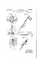
- Fig. 1 is a front elevation of the preferred form of the invention, showing the thread guide in operative relation to the carrier rods and the sinkers and dividers of a flat knitting machine;
- Fig. 2 is a transverse sectional elevation taken on the line 2--2, Fig.1;
- Fig. 3 is an enlarged transverse sectional elevation taken on the line 3-3, Fig. 1;
- Fig. 4 is a view similar to Fig. 1 illustrating a modified form of the invention
- Fig. 5 is a transverse sectional elevation taken on the line 55, Fig. 4;
- Fig. 6 is an enlarged transverse sectional vation'taken on the line 6--6, Fig. 4;
- Fig. '7 is a sectional elevation taken on the line 'I-l, Fig. 6.
- Figs. 1, 2, 4 and 5 of the drawings three of the carrier rods of an ordinary full-fashioned hosiery knitting machine are illustrated at l, I. Normally these machines are provided with seven such carrier bars and in the above noted threecarr ier method of knitting three of the bars are used in predetermined order for respectively laying individual threads controlled thereby between the needles'and sinkers of the machine.
- the sinkers of the machine are illustrated at 2, 2 which, as shown in Figs. 1 and 4, alternate across the machine with the dividers 3, 3.
- the sinkers are normally projected outwardly across the path of movement of the thread carriers from the full line to the broken line positions shown in Figs. 2 and 5, by individual jacks i which are elesuccessively rocked to effect projection of the sinkers, behind the thread guide as the thread guide advances across the knitting head, by a slur cock illustrated at 5.
- each of the thread carrier rods is provided with a thread guide unit l and each unit l0 comprises a thread guide holder II which is secured to a carrier bar I, as by screws i2.
- the thread guide unit comprises a single rigid element secured to the holder II, as by screws l3, such rigid element comprising a more or less delicate thread-guiding tube l4 at its lower end which is adapted to move past the front'shoulder edges l5 of the sinkers and dividers 2 and 3, above the top edges i6 of the thread supporting tongues l1 of said-sinkers and dividers and below the top edges l8 thereof, in view of which it will be readily seen that should any one of the sinkers or dividers be disposed in the broken line position "of Figs.
- a thread guide madein accordance with the principles of the present invention is composed of two pivotally connected members 20 and 2
- the up- -per member 20 is illustrated as being ofiset at 23, in order that the two elements 26 and 2
- the pivot element 22 is rigidly secured in a longitudinally extending projection 24 of the upper member 20 disposed below the offset 23.
- of the unit II in the present instance, is provided with a springpressed detent comprising in the preferred form of the invention a resilient tongue 25 which extends upwardly beyond the ofiset 23 or the upper part 20 in overlapping relation to and in contact with said upper member 20.
- the resilient tongue 25 is provided with a detent 26 which normally lies in a spot depression 21 formed ln'the upper member 20 of the thread guide unit ill.”
- the resilient tongue 25 in the present instance is secured to the lower member 2
- the depth of the depression 21 is Just enough to maintain alignment of the members 26 and 2
- tent 26 will ride out of the depression 21 to a position beyond one or the other of the side edges 29, 29 of the upper member of .the thread guide, thereby retaining the .lower member 2
- for a modified form of spring-pressed detent 26a Secured to the upper member 20a of the thread guide immediately above the upper edge 30 of the lower member Zia thereof is a housing 3
- the spring-pressed detent is in the form of a beveled lower end 3311 of a plunger 32 slidably mounted in the housing 3
- in the present case is of a sheet metal construction having flanges 36, 36 resting against the under surface of the member 2011 and secured thereto by any suitable means such as rivets 31, 31.
- the said lower member is maintained in said inoper ative position, until manually restored to the normal operating position in longitudinal alignment with the upper member 20 a of the thread guide, in the same manner as the lower member 2
- thread guide means effecting relative movement between the sinkers and the thread guide transversely thereof, means pivotally supporting said thread, guide on said movement eflecting means; means resiliently maintaining the thread-guide normally izi-thread-laying relation to the sinkers and permitting rearward movement of the guide in either direction of travel upon engagement with a sinker, and means maintaining said thread guide in an inoperative position relative to the sinkers resulting from 'pivotal movement of the thread guide relative to said movement effecting means by contact of the thread guide with one'of said sinkers.
- a knitting machine thread guide comprising an upper rigidly mountable member, a lower member pivotally mounted on said upper member, and a resilient tongue on one of said members overlapping and contacting with theother of said members, a detent on the resilient tongue normally pressed thereby into a depression in said overlapped member for maintaining said members resiliently in normal thread-laying relation to each other or engageable with a side edge of said overlapped member to retain said members in inoperative relation upon relative pivotal movement between said members.
- a knitting machine thread guide comprising a pair of pivotally connected members, a rounded end on one member and provided with circumferentially spaced peripheral notches, and a spring-pressed detent carried by the other of said members engageable with the peripheral notches of the other member for maintaining said members in either a normal thread-laying relation 30 to each other or in inoperative relation to each between machines having a plurality of movable sinkers and provision for reciprocating the yarn carrier to lay yarn along said sinkers, said yarn carrier comprising an upper rigidly mountable member, a lower member pivotally attached to said upper member, and a spring pressed detent carried by one of said members and entering a depression in the other of said members normally maintaining said members resiliently in normal thread laying relation one to the other and per- ;mitting rearward movement of the lower member in either direction of travel upon engagement with a sinker.
- a yarn carrier for use in straight knitting machines having a' plurality of movable sinkers and provision for reciprocating the yarn carrier to lay yarn along said sinkers, said yarn carrier comprising an upper rigidly mountable member, a lower yarn laying member pivotally mounted on said upper member for rearward movement from the normal yarn laying position in either direction of travel, a resilient tongue on one of said members overlapping the other of said members, and cooperating means on said tongue and said overlapped member respectively for resiliently maintaining said members in normal JOHN o. waron'rson.
Description
July 20,1937. J. o. WRIGHTSON 2,087,830
THREAD GUIDE FOR STRAIGHT KNITTING MACHINES Filed Oct. 2, 1934 2 Sheets-Sheet l ly 1937' J. o. WRIGHTSON 8 ,8
THREAD GUIDE FOR STRAIGHT KNITTING MACHINES Filed Oqt. 2 1934 I 2 Sheets-Sheet 2 awne iv v Patented Jilly 20, 1937 UNITED STATES PATENT OFFICE John 0. Wrightson, Philadelphia, Pa., assignor to Arcadia-Hosiery 00., Lansdale,
tion of Pennsylvania 2a., a corpora- Appiication October 2, 1934, Serial No. 746,607
Claims. C1. 66-126) This invention relates to thread carriers for knitting machines. and particularly those used on fiat machines of the type commonly employed in the manufacture of full fashioned hosiery.
The object ofthis invention .is to provide a thread guide which will not injure the sinkers of the knitting machine nor will itself become in ured as a result of the motion for efiecting needle-traversing movement of thethread guide getting out of time with the motion which projects the sinkers of the machine outwardly across the path of the thread guide, 1. e. in cases where the sinkers are projected in advance of the thread guide instead of behind the thread guide as the thread guide is moved in opposite directions alternately in a plane parallel to and intermediate v that of the front ends of the sinkers and the plane of the bank of needles with which the sinkers cooperate.
This invention is particularly adaptable for use with the recently developed three-carrier knitting process, adapted for eliminating rings in sheer hosiery, wherein each of the three individual thread carriers employed makes but a single needle-traversing movement at any one time, which requires the disconnection of each carrier rod from the Coulier motion of the machine or a friction box driven by said motion after the thread guide has laid thread for one course of stitches and the reconnection of a different carrier rod .to the mechanism which eiiects the needle-traversing movements of the thread guides before a thread is laid to the needles for the formation of a succeeding course of stitches. This recurrent connecting and disconnecting of the thread barsor carrier rods frequently causes one 'or more of the thread guidesto be movedout of time with the slur cock, also driven by the Coulier motion, by which the sinkers are projected across the path of the thread guide.
, With the usual rigid thread guide, the projecting of a sinker in advance of the thread guide instead of behind the thread guide results in damage to either the thread guide the sinkers, or both and most often to the sinkers, whichare of a more or less delicate construction.
4 The thread guide constituting the subject matter of the present invention is so constructed that, in event of the lower endof the thread guide contacting with any one of the sinkers in the course of travel of the thread guide across the series of sinkers, such contact will result in the lower end of the thread guide being-moved 1 ;t aliy to an inoperative-position above the tops 01' the sinkers without damage being done to either the thread guide or the sinkers.
Alternating with the sinkers is a series of dividers which are of substantially the same construction as the sinkers and which are projected outwardly between the sinkers, after the sinkers have been successively projected, in order to divide the thread equally around and between each and all of the needles then operating in any single knitting head of the machine.
During certain parts of the knitting operation the sinkers and dividers are operated en masse by .the catch bar of the machine and if for any reason one or more of the sinkers ordividers shall fail to be retracted by the catch bar and be left in a projected position until the thread guide makes its next needle-traversing movement the thread guide will upon engaging the projected divider or sinker be moved to the inoperative position above noted, thereby avoiding damage to either the sinkers, dividers, or the thread guides by any improper relation of the elements at such time.
In the accompanying drawings:
Fig. 1 is a front elevation of the preferred form of the invention, showing the thread guide in operative relation to the carrier rods and the sinkers and dividers of a flat knitting machine;
Fig. 2 is a transverse sectional elevation taken on the line 2--2, Fig.1;
Fig. 3 is an enlarged transverse sectional elevation taken on the line 3-3, Fig. 1;
Fig. 4 is a view similar to Fig. 1 illustrating a modified form of the invention;
Fig. 5 is a transverse sectional elevation taken on the line 55, Fig. 4;
Fig. 6 is an enlarged transverse sectional vation'taken on the line 6--6, Fig. 4; and
Fig. '7 is a sectional elevation taken on the line 'I-l, Fig. 6.
In Figs. 1, 2, 4 and 5 of the drawings, three of the carrier rods of an ordinary full-fashioned hosiery knitting machine are illustrated at l, I. Normally these machines are provided with seven such carrier bars and in the above noted threecarr ier method of knitting three of the bars are used in predetermined order for respectively laying individual threads controlled thereby between the needles'and sinkers of the machine.
The sinkers of the machine are illustrated at 2, 2 which, as shown in Figs. 1 and 4, alternate across the machine with the dividers 3, 3. The sinkers are normally projected outwardly across the path of movement of the thread carriers from the full line to the broken line positions shown in Figs. 2 and 5, by individual jacks i which are elesuccessively rocked to effect projection of the sinkers, behind the thread guide as the thread guide advances across the knitting head, by a slur cock illustrated at 5.
Each of the thread carrier rods is provided with a thread guide unit l and each unit l0 comprises a thread guide holder II which is secured to a carrier bar I, as by screws i2. Normally the thread guide unit comprises a single rigid element secured to the holder II, as by screws l3, such rigid element comprising a more or less delicate thread-guiding tube l4 at its lower end which is adapted to move past the front'shoulder edges l5 of the sinkers and dividers 2 and 3, above the top edges i6 of the thread supporting tongues l1 of said-sinkers and dividers and below the top edges l8 thereof, in view of which it will be readily seen that should any one of the sinkers or dividers be disposed in the broken line position "of Figs. 2 and 5 when the rigid lower member of the thread guide unit is moving across the sinker bed damage will be done to either one or the other or bothof the elements, usually to the more delicate sinker or divider and frequently to the thread-guiding tube l4. Such a condition necessitates the shutting down of the machine for some time to repair the damage, which means the interruption of the knitting operation in anywhere from eighteen to twenty-four stockings which are being simultaneously produced on the machine.
A thread guide madein accordance with the principles of the present invention, instead of being of a rigid nature from the holder II to the tube i4, is composed of two pivotally connected members 20 and 2| respectively, the first of which is rigidly secured to the holder II by the screws l3 while the latter. is pivotally connected to the former as by a screw, rivet, or other" equivalent element 22, in order to provide for the pivotal support of the lower member 2|.
In the preferred form of the invention the up- -per member 20 is illustrated as being ofiset at 23, in order that the two elements 26 and 2| may be disposed in substantially the same plane. The pivot element 22 is rigidly secured in a longitudinally extending projection 24 of the upper member 20 disposed below the offset 23.
Normally'the upper and lower members 20 and 2| are longitudinally aligned one with the other and in order to maintain this normal alignment between the pivotally connected parts, against the normal tension oi! the thread as placed thereon by the sinkers 2 moving out behind the thread guide and pressing the thread between the needles, the lower part 2| of the unit II, in the present instance, is provided with a springpressed detent comprising in the preferred form of the invention a resilient tongue 25 which extends upwardly beyond the ofiset 23 or the upper part 20 in overlapping relation to and in contact with said upper member 20. The resilient tongue 25 is provided with a detent 26 which normally lies in a spot depression 21 formed ln'the upper member 20 of the thread guide unit ill."
The resilient tongue 25 in the present instance is secured to the lower member 2| 0! the thread guide unit I II by ' screws 26, 26 respectively located at opposite sides of the pivot 22 longitudinally of the unit ill;
The depth of the depression 21 is Just enough to maintain alignment of the members 26 and 2| under normal thread tension and in event of the tube l4, which is carried by the lower part of the lower member 2| or the thread guide, or any other portion of the lower part of the thread guide adjacent the tube l4, striking an abnormally projected sinker or divider the lower member 2| will swing about the pivot 22 from the normal full line position shown in Figs. 1 and 4 to either of the 5 broken line positions a: or m illustrated in said figures, depending upon the direction in which the thread guide happens to be moving at the time, in which case in the form of the invention shown in Figs. 1, 2 and 3 the spring-pressed, de-
In that form of the invention shown in-Figs. 4,
5, 6 and '7, the resilient tongue on the lower portion 2| and the rigid tongue on the upper portion 20 of the thread guide unit are eliminated 20 pivot screw 22a, by which the members 20a, 2| a 30 are pivotally secured together.
Secured to the upper member 20a of the thread guide immediately above the upper edge 30 of the lower member Zia thereof is a housing 3| for a modified form of spring-pressed detent 26a. In
this case the spring-pressed detent is in the form of a beveled lower end 3311 of a plunger 32 slidably mounted in the housing 3| and adapted normally to rest in a central V-shaped notch or depression 34 forming in the rounded edge 30 of the lower member 2|a of the thread guide, said detent being resiliently held in said notch by a compression spring 25a mounted in the housing 3| behind the plunger 32.
The housing 3| in the present case is of a sheet metal construction having flanges 36, 36 resting against the under surface of the member 2011 and secured thereto by any suitable means such as rivets 31, 31.
The operation of the modified form shown in Figs. 4 to 7 inclusive is substantially the same as that of the preferred form shown in Figs. 1 to 3 inclusive, and when the lower member 2hr is swung into either of the inoperative positions a: or x the detent 26a is forced out of the centraf v-shaped notch 34 and enters one or the other of a pairof laterally spaced notches 29a29a termed in the upper rounded edge 30 of the lower member 2|a of .the thread guide, whereby. the said lower member is maintained in said inoper ative position, until manually restored to the normal operating position in longitudinal alignment with the upper member 20 a of the thread guide, in the same manner as the lower member 2| is held in inoperative relation to the upper member 26 in the preferred form of ,the invention, by the spring-pressed detent 26 engaging one of the side edges 29 or the upper member 20. I claim: lfThe combination of a series of sinkers, a
, thread guide, means effecting relative movement between the sinkers and the thread guide transversely thereof, means pivotally supporting said thread, guide on said movement eflecting means; means resiliently maintaining the thread-guide normally izi-thread-laying relation to the sinkers and permitting rearward movement of the guide in either direction of travel upon engagement with a sinker, and means maintaining said thread guide in an inoperative position relative to the sinkers resulting from 'pivotal movement of the thread guide relative to said movement effecting means by contact of the thread guide with one'of said sinkers.
2. A knitting machine thread guide comprising an upper rigidly mountable member, a lower member pivotally mounted on said upper member, and a resilient tongue on one of said members overlapping and contacting with theother of said members, a detent on the resilient tongue normally pressed thereby into a depression in said overlapped member for maintaining said members resiliently in normal thread-laying relation to each other or engageable with a side edge of said overlapped member to retain said members in inoperative relation upon relative pivotal movement between said members.
3. A knitting machine thread guide comprising a pair of pivotally connected members, a rounded end on one member and provided with circumferentially spaced peripheral notches, and a spring-pressed detent carried by the other of said members engageable with the peripheral notches of the other member for maintaining said members in either a normal thread-laying relation 30 to each other or in inoperative relation to each between machines having a plurality of movable sinkers and provision for reciprocating the yarn carrier to lay yarn along said sinkers, said yarn carrier comprising an upper rigidly mountable member, a lower member pivotally attached to said upper member, and a spring pressed detent carried by one of said members and entering a depression in the other of said members normally maintaining said members resiliently in normal thread laying relation one to the other and per- ;mitting rearward movement of the lower member in either direction of travel upon engagement with a sinker. l
, 5'. A yarn carrier for use in straight knitting machines having a' plurality of movable sinkers and provision for reciprocating the yarn carrier to lay yarn along said sinkers, said yarn carrier comprising an upper rigidly mountable member, a lower yarn laying member pivotally mounted on said upper member for rearward movement from the normal yarn laying position in either direction of travel, a resilient tongue on one of said members overlapping the other of said members, and cooperating means on said tongue and said overlapped member respectively for resiliently maintaining said members in normal JOHN o. waron'rson.
Priority Applications (1)
| Application Number | Priority Date | Filing Date | Title |
|---|---|---|---|
| US746607A US2087830A (en) | 1934-10-02 | 1934-10-02 | Thread guide for straight knitting machines |
Applications Claiming Priority (1)
| Application Number | Priority Date | Filing Date | Title |
|---|---|---|---|
| US746607A US2087830A (en) | 1934-10-02 | 1934-10-02 | Thread guide for straight knitting machines |
Publications (1)
| Publication Number | Publication Date |
|---|---|
| US2087830A true US2087830A (en) | 1937-07-20 |
Family
ID=25001561
Family Applications (1)
| Application Number | Title | Priority Date | Filing Date |
|---|---|---|---|
| US746607A Expired - Lifetime US2087830A (en) | 1934-10-02 | 1934-10-02 | Thread guide for straight knitting machines |
Country Status (1)
| Country | Link |
|---|---|
| US (1) | US2087830A (en) |
Cited By (5)
| Publication number | Priority date | Publication date | Assignee | Title |
|---|---|---|---|---|
| US2426357A (en) * | 1944-03-25 | 1947-08-26 | Louis Kotzen E | Knitting apparatus and method |
| US2555920A (en) * | 1948-07-06 | 1951-06-05 | Russell D Curry | Yarn carrier for knitting machines |
| US2569904A (en) * | 1948-01-14 | 1951-10-02 | Otto M Schmidt | Thread carrier |
| US2656693A (en) * | 1951-11-16 | 1953-10-27 | Textile Machine Works | Yarn carrier of knitting machines |
| US3029620A (en) * | 1957-09-28 | 1962-04-17 | Steinhof Apparatefab Karl | Thread guide for knitting machine |
-
1934
- 1934-10-02 US US746607A patent/US2087830A/en not_active Expired - Lifetime
Cited By (5)
| Publication number | Priority date | Publication date | Assignee | Title |
|---|---|---|---|---|
| US2426357A (en) * | 1944-03-25 | 1947-08-26 | Louis Kotzen E | Knitting apparatus and method |
| US2569904A (en) * | 1948-01-14 | 1951-10-02 | Otto M Schmidt | Thread carrier |
| US2555920A (en) * | 1948-07-06 | 1951-06-05 | Russell D Curry | Yarn carrier for knitting machines |
| US2656693A (en) * | 1951-11-16 | 1953-10-27 | Textile Machine Works | Yarn carrier of knitting machines |
| US3029620A (en) * | 1957-09-28 | 1962-04-17 | Steinhof Apparatefab Karl | Thread guide for knitting machine |
Similar Documents
| Publication | Publication Date | Title |
|---|---|---|
| US2087830A (en) | Thread guide for straight knitting machines | |
| US3055196A (en) | Apparatus and method for making pile fabric with varying height of pile | |
| US2293838A (en) | Selective machine stopping means positively operated upon yarn cessation in yarn-changing furnishing mechanism | |
| US2104815A (en) | Thread carrier device | |
| US2289052A (en) | Knitting machine | |
| US2082642A (en) | Sinker or web holder control | |
| US2277797A (en) | Multiple section flat knitting machine | |
| US2737794A (en) | Yarn carrier for full-fashioned knitting machines | |
| US2092619A (en) | Yarn guide for knitting machines | |
| US2014341A (en) | Thread carrier for knitting machines | |
| US1626781A (en) | Island | |
| US2509032A (en) | Knitting machine | |
| US2381376A (en) | Slur cam for knitting machines | |
| US2187715A (en) | Method of and apparatus for knitting | |
| US2203693A (en) | Knitting machine | |
| US3390550A (en) | Fabric draw-off means for knitting machines | |
| US687379A (en) | Knitting-machine. | |
| US2265100A (en) | Knitting machine | |
| US1228483A (en) | Knitting-machine. | |
| US1406514A (en) | Cibcttlas-xnitting machine | |
| USRE20025E (en) | Machine for knitting fabric | |
| US53013A (en) | Improvement in knitting-machines | |
| US2093789A (en) | Knitting machine | |
| US965351A (en) | Yarn-changer for circular-knitting machines. | |
| US1580072A (en) | Striping-finger construction for knitting machines |