US2082610A - Hedge trimmer - Google Patents
Hedge trimmer Download PDFInfo
- Publication number
- US2082610A US2082610A US36305A US3630535A US2082610A US 2082610 A US2082610 A US 2082610A US 36305 A US36305 A US 36305A US 3630535 A US3630535 A US 3630535A US 2082610 A US2082610 A US 2082610A
- Authority
- US
- United States
- Prior art keywords
- hedge trimmer
- guide rods
- supporting plate
- fixed
- pair
- Prior art date
- Legal status (The legal status is an assumption and is not a legal conclusion. Google has not performed a legal analysis and makes no representation as to the accuracy of the status listed.)
- Expired - Lifetime
Links
Images
Classifications
-
- A—HUMAN NECESSITIES
- A01—AGRICULTURE; FORESTRY; ANIMAL HUSBANDRY; HUNTING; TRAPPING; FISHING
- A01G—HORTICULTURE; CULTIVATION OF VEGETABLES, FLOWERS, RICE, FRUIT, VINES, HOPS OR SEAWEED; FORESTRY; WATERING
- A01G3/00—Cutting implements specially adapted for horticultural purposes; Delimbing standing trees
- A01G3/04—Apparatus for trimming hedges, e.g. hedge shears
- A01G3/047—Apparatus for trimming hedges, e.g. hedge shears portable
- A01G3/053—Apparatus for trimming hedges, e.g. hedge shears portable motor-driven
Definitions
- My invention relates to a hedge trimmer somewhat of the type disclosed in my Patent numbered 1,839,009 and issued on the 29th day of December, 1931.
- Important objects of 'the invention are to provide a hedge trimmer of the character described, which is adapted to be attached to a power propelled vehicle, which is power operated, which embodies a cutting element that may be readily adjusted to any desired cutting height and angle, and which will facilitate and expedite hedge trimming operations.
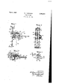
- Figure 1 is a rear elevational view of a hedge trimmer, constructed in accordance with the invention.
- Figures 2 and 3 are, respectively, side and top plan views thereof.
- Figure 4 is a rear view of the adjusting disk and of associated parts.
- the guide rods extend vertically and parallel to each other, and have their upper ends fixed in the head member 3, while the lower ends thereof are fixed in the foot member 4.
- the head and foot members 3 and 4 are each provided with an integrally formed, laterally projecting connecting bracket, respectively indicated at 5 and 6.
- the connecting brackets are apertured and adapted for attaching the device in position to a motor truck or tractor, or to any other suitable propelling vehicle.
- a slide block 1 is mounted for vertical movement on the guide rods 2, which latter extend through the former.
- An adjusting screw 8 is suitably journaled for rotation in the head and foot members 3 and 4, and is disposed parallel to and centrally intermediate of the guide rods. The adjusting screw extends through the slide block and is threadedly engaged in the latter.
- the upper end of the adjusting screw 8 carries a fixed, handled, operating wheel 9 to facilitate the rotation of the screw when vertically adjusting the slide block 1 on the guide rods 2.
- the slide block 1 is provided with an integrally formed or otherwise fixed supporting plate I, which is disposed vertically edgewise.
- the supporting plate carries a pair of fixed axles, respectively indicated at II and I2.
- the axles II and I2 are horizontally aligned, having a common axis, and project laterally on opposed sides of the supporting plate.
- a connecting diskl I3 is pivotally mounted, at its axial center, on the axle II, and carries a cutter bar I4, which is xed therewith in any suitable manner.
- the cutter bar is of the wellknown construction and includes the slotted iingers I5, through which the cutter member I6, having triangularly-shaped knives, reciprocates in the usual manner during the cutting operation.
- Reciprocating movement is imparted to the cutter member I6 by a pitman I'I, which has one end pivotally connected to the inner end of the former.
- the other end of the pitman is pivotally and eccentrically connected to a pinion I8, which is pivotally connected against the rear side of the supporting plate I0.
- the pinion is driven by a driving gear I9, which is revolubly connected on the axle I2 rearwardly of the supporting plate.
- An electric motor 20 is secured in position on a bracket 2
- the motor 20 is provided with a motor gear 22, which meshes with and operates the driving gear I9.
- gear teeth 23 which mesh with a worm 24 fixed on a shaft 25.
- the latter is suitably journaled for rotation in bearings 26, which latter are carried by and xed to the supporting plate I0 at the top of the latter.
- the shaft 25 projects through the frame structure l, and carries a Xed, handled operating wheel 2l'.
- the operation of the latter will eiTect the adjustment of the cutter bar hland of the associated cutter member I6 from the horizontal position to predetermined angular positions either above or below the latter, as clearly illustrated in Figure 1.
- the location and relative positions of the 9perating wheels 9 and 2l are such as to ⁇ 'conveniently permit their manipulation by the operator,
- the present invention provides a mosteiicient device of its kind), which may be conveniently operated to neatly, quickly and accurately wtrim a hedge row along vits top and along respective sides thereof.
- a hedge trimmer of the character described comprising a pair of vertically extending spaced guide rods, head and foot members xed to respective ends of said pair of guide rods, an attaching bracket fixed to each of said head and foot members, a block including a supporting plate slidably mounted on said pair of guide rods, an adjusting screw threadedly engaging said block disposed parallel to and intermediate of said pair of guide rods and journaled for rotation in said head and ⁇ foot members, a wheel fixed to the upper, Vend of said adjusting screw to operate the latter to vertically shift said block on said pair of guide rods, a connecting ⁇ disk pivotally joined to said supporting plate, a cutter bar fixed to said connecting disk,
Description
June 1, 1937.
W. R. BANKSON HEDGE TRIMMER Filed Aug. l5, 1935 mum Patented June 1, 1937 UNITED STATES PATENT OFFICE 1 Claim.
My invention relates to a hedge trimmer somewhat of the type disclosed in my Patent numbered 1,839,009 and issued on the 29th day of December, 1931.
Important objects of 'the invention are to provide a hedge trimmer of the character described, which is adapted to be attached to a power propelled vehicle, which is power operated, which embodies a cutting element that may be readily adjusted to any desired cutting height and angle, and which will facilitate and expedite hedge trimming operations.
With the foregoing and other objects in view which will appear as the description proceeds, the invention resides in the novel construction, combination and arrangement of parts herein specifically described and illustrated in the accompanying drawing, but it is to be understood that changes in the form, proportions and details of construction may be resorted to that come within the scope of the claims hereunto appended.
In the drawing wherein like numerals of reference designate corresponding parts throughout the several views:
Figure 1 is a rear elevational view of a hedge trimmer, constructed in accordance with the invention.
Figures 2 and 3 are, respectively, side and top plan views thereof.
Figure 4 is a rear view of the adjusting disk and of associated parts.
Referring in detail to the drawing I denotes the entire frame structure, which comprises a pair of spaced guide rods 2, a head member 3, and a foot member 4. The guide rods extend vertically and parallel to each other, and have their upper ends fixed in the head member 3, while the lower ends thereof are fixed in the foot member 4.
The head and foot members 3 and 4 are each provided with an integrally formed, laterally projecting connecting bracket, respectively indicated at 5 and 6. The connecting brackets are apertured and adapted for attaching the device in position to a motor truck or tractor, or to any other suitable propelling vehicle.
A slide block 1 is mounted for vertical movement on the guide rods 2, which latter extend through the former. An adjusting screw 8 is suitably journaled for rotation in the head and foot members 3 and 4, and is disposed parallel to and centrally intermediate of the guide rods. The adjusting screw extends through the slide block and is threadedly engaged in the latter.
The upper end of the adjusting screw 8 carries a fixed, handled, operating wheel 9 to facilitate the rotation of the screw when vertically adjusting the slide block 1 on the guide rods 2.
The slide block 1 is provided with an integrally formed or otherwise fixed supporting plate I, which is disposed vertically edgewise. The supporting plate carries a pair of fixed axles, respectively indicated at II and I2. The axles II and I2 are horizontally aligned, having a common axis, and project laterally on opposed sides of the supporting plate.
A connecting diskl I3 is pivotally mounted, at its axial center, on the axle II, and carries a cutter bar I4, which is xed therewith in any suitable manner. The cutter bar is of the wellknown construction and includes the slotted iingers I5, through which the cutter member I6, having triangularly-shaped knives, reciprocates in the usual manner during the cutting operation.
Reciprocating movement is imparted to the cutter member I6 by a pitman I'I, which has one end pivotally connected to the inner end of the former. The other end of the pitman is pivotally and eccentrically connected to a pinion I8, which is pivotally connected against the rear side of the supporting plate I0. The pinion is driven by a driving gear I9, which is revolubly connected on the axle I2 rearwardly of the supporting plate.
An electric motor 20 is secured in position on a bracket 2|, which latter projects rearwardly of and is iixed to the supporting plate I0. The motor 20 is provided with a motor gear 22, which meshes with and operates the driving gear I9.
It is evident that the operation of the motor 20 will drive the gear I9 and associated pinion I8, and thereby impart longitudinal reciprocation of the cutter member I6 in the cutter bar I4 to effect the cutting or trimming operations, in a manner well known in the art.
It will here be noted that, while illustrating and describing an electric motor for driving my improved hedge trimmer, it is evident that any other adaptable power mechanism may be employed, namely, an internal combustion engine, or a suitable driving connection with the power mechanism embodied in the propelling vehicle to which the device is attached.
Approximately one-half portion of the periphery of the connecting disk I3 is provided with gear teeth 23, which mesh with a worm 24 fixed on a shaft 25. The latter is suitably journaled for rotation in bearings 26, which latter are carried by and xed to the supporting plate I0 at the top of the latter.
The shaft 25 projects through the frame structure l, and carries a Xed, handled operating wheel 2l'. The operation of the latter will eiTect the adjustment of the cutter bar hland of the associated cutter member I6 from the horizontal position to predetermined angular positions either above or below the latter, as clearly illustrated in Figure 1.
As the driving gear I9 and the connecting disk i3 have a common axial center, the adjustment of the cutter bar I4, in the manner stated, will not affect the 4functioning of the pinion t8, regardless of the relative position of the latter with respect to the driving gear I9.
The location and relative positions of the 9perating wheels 9 and 2l are such as to `'conveniently permit their manipulation by the operator,
to provide -1 the required or desired height and angular adjustments of the cutting elements.-
The present invention provides a mosteiicient device of its kind), which may be conveniently operated to neatly, quickly and accurately wtrim a hedge row along vits top and along respective sides thereof. -f
-What I claim vis: f
-In combination, a hedge trimmer of the character described, comprising a pair of vertically extending spaced guide rods, head and foot members xed to respective ends of said pair of guide rods, an attaching bracket fixed to each of said head and foot members, a block including a supporting plate slidably mounted on said pair of guide rods, an adjusting screw threadedly engaging said block disposed parallel to and intermediate of said pair of guide rods and journaled for rotation in said head and `foot members, a wheel fixed to the upper, Vend of said adjusting screw to operate the latter to vertically shift said block on said pair of guide rods, a connecting `disk pivotally joined to said supporting plate, a cutter bar fixed to said connecting disk,
l.a reciprocating `cutter member mounted in said cutter bar, power operated means carried by said `supporting vplate and operable for imparting re-
Priority Applications (1)
| Application Number | Priority Date | Filing Date | Title |
|---|---|---|---|
| US36305A US2082610A (en) | 1935-08-15 | 1935-08-15 | Hedge trimmer |
Applications Claiming Priority (1)
| Application Number | Priority Date | Filing Date | Title |
|---|---|---|---|
| US36305A US2082610A (en) | 1935-08-15 | 1935-08-15 | Hedge trimmer |
Publications (1)
| Publication Number | Publication Date |
|---|---|
| US2082610A true US2082610A (en) | 1937-06-01 |
Family
ID=21887847
Family Applications (1)
| Application Number | Title | Priority Date | Filing Date |
|---|---|---|---|
| US36305A Expired - Lifetime US2082610A (en) | 1935-08-15 | 1935-08-15 | Hedge trimmer |
Country Status (1)
| Country | Link |
|---|---|
| US (1) | US2082610A (en) |
Cited By (7)
| Publication number | Priority date | Publication date | Assignee | Title |
|---|---|---|---|---|
| US2645074A (en) * | 1951-02-15 | 1953-07-14 | Luther Selvia | Adjustable reel-type hedge trimmer |
| US2676447A (en) * | 1950-07-18 | 1954-04-27 | Asbury Corp | Lawn edger attachment |
| US2721433A (en) * | 1951-10-24 | 1955-10-25 | George D Berdan | Lawn edger and trimmer |
| US3703803A (en) * | 1972-01-31 | 1972-11-28 | James N Mcclure | Mobile variable head, hedge trimmer |
| US3731476A (en) * | 1972-02-14 | 1973-05-08 | Shook Alvin L | Hedge trimmer |
| US3961468A (en) * | 1973-12-21 | 1976-06-08 | Harlo Products Corporation | Hedger |
| US6715272B2 (en) * | 2002-07-15 | 2004-04-06 | Ira Stahl | Device and method for supporting a self-powered hedge cutter |
-
1935
- 1935-08-15 US US36305A patent/US2082610A/en not_active Expired - Lifetime
Cited By (7)
| Publication number | Priority date | Publication date | Assignee | Title |
|---|---|---|---|---|
| US2676447A (en) * | 1950-07-18 | 1954-04-27 | Asbury Corp | Lawn edger attachment |
| US2645074A (en) * | 1951-02-15 | 1953-07-14 | Luther Selvia | Adjustable reel-type hedge trimmer |
| US2721433A (en) * | 1951-10-24 | 1955-10-25 | George D Berdan | Lawn edger and trimmer |
| US3703803A (en) * | 1972-01-31 | 1972-11-28 | James N Mcclure | Mobile variable head, hedge trimmer |
| US3731476A (en) * | 1972-02-14 | 1973-05-08 | Shook Alvin L | Hedge trimmer |
| US3961468A (en) * | 1973-12-21 | 1976-06-08 | Harlo Products Corporation | Hedger |
| US6715272B2 (en) * | 2002-07-15 | 2004-04-06 | Ira Stahl | Device and method for supporting a self-powered hedge cutter |
Similar Documents
| Publication | Publication Date | Title |
|---|---|---|
| US2082610A (en) | Hedge trimmer | |
| CN208071948U (en) | A kind of sewing machine laser cloth-cutting apparatus | |
| US1713396A (en) | Gardening implement | |
| US1839009A (en) | Hedge trimmer | |
| US2161357A (en) | Hedge and lawn clipper | |
| US3074221A (en) | Power lawnmower | |
| US1610498A (en) | Power mower | |
| US1351939A (en) | Shearing and mowing machine | |
| US1716085A (en) | Lawn mower | |
| US1857342A (en) | Hedge cutter | |
| US3581497A (en) | Control apparatus for hydraulic drive mechanism | |
| US1054320A (en) | Grass cutter and trimmer. | |
| US2503521A (en) | Transmission mechanism | |
| US1897543A (en) | Hedge cutter | |
| US3407579A (en) | Lawnmower edger attachment | |
| US1324032A (en) | Poweb-handsaw | |
| US3083518A (en) | Tall weed lawn mower attachment | |
| US2507371A (en) | Saw sharpener | |
| GB1314377A (en) | Lawn mowers | |
| US1797957A (en) | Driving attachment for tractors | |
| US1609101A (en) | Motor-driven lawn mower and rake | |
| US2005440A (en) | Bean cutter | |
| US1679421A (en) | Hedge trimmer | |
| US1805864A (en) | Hand mower | |
| US2692508A (en) | Device for converting rotary motion to reciprocating motion |