US2080098A - Electron discharge tube - Google Patents
Electron discharge tube Download PDFInfo
- Publication number
- US2080098A US2080098A US703239A US70323933A US2080098A US 2080098 A US2080098 A US 2080098A US 703239 A US703239 A US 703239A US 70323933 A US70323933 A US 70323933A US 2080098 A US2080098 A US 2080098A
- Authority
- US
- United States
- Prior art keywords
- grid
- cathode
- screen
- anode
- tube
- Prior art date
- Legal status (The legal status is an assumption and is not a legal conclusion. Google has not performed a legal analysis and makes no representation as to the accuracy of the status listed.)
- Expired - Lifetime
Links
- 239000000523 sample Substances 0.000 description 13
- 230000010355 oscillation Effects 0.000 description 5
- 239000002184 metal Substances 0.000 description 3
- 230000000979 retarding effect Effects 0.000 description 3
- 230000003321 amplification Effects 0.000 description 2
- 239000000463 material Substances 0.000 description 2
- 238000003199 nucleic acid amplification method Methods 0.000 description 2
- 238000006243 chemical reaction Methods 0.000 description 1
- 238000010276 construction Methods 0.000 description 1
- 230000008878 coupling Effects 0.000 description 1
- 238000010168 coupling process Methods 0.000 description 1
- 238000005859 coupling reaction Methods 0.000 description 1
- 230000000694 effects Effects 0.000 description 1
- 239000011521 glass Substances 0.000 description 1
- 230000004048 modification Effects 0.000 description 1
- 238000012986 modification Methods 0.000 description 1
- 230000001105 regulatory effect Effects 0.000 description 1
Images
Classifications
-
- H—ELECTRICITY
- H01—ELECTRIC ELEMENTS
- H01J—ELECTRIC DISCHARGE TUBES OR DISCHARGE LAMPS
- H01J21/00—Vacuum tubes
- H01J21/20—Tubes with more than one discharge path; Multiple tubes, e.g. double diode, triode-hexode
-
- H—ELECTRICITY
- H01—ELECTRIC ELEMENTS
- H01J—ELECTRIC DISCHARGE TUBES OR DISCHARGE LAMPS
- H01J2893/00—Discharge tubes and lamps
- H01J2893/003—Tubes with plural electrode systems
Definitions
- the present invention relates to electron tubes and circuits therefor, and more particularly is concerned with a tube of the screen-grid type which is supplementarily equipped with a rectifier path.
- Apparatus used for reception and demodulation of electrical oscillations can be built far more favorably if the demodulation or rectification is effected in a distinct rectifier without amplification, such as a two-electrode or diode tube. It has been suggested to combine such rectifier together with an amplifier system in one and the same vacuum vessel so that both systems to be sure, constitute a constructional unit, while yet remaining separate as regards their electrical effects. The amplifying and the rectifying systems must then be disposed adjacent to each other over a sufiic'ien-tly long cathode.
- a marked disadvantage of this arrangement consists in that the length of the cathode must be greater than that for the amplifying system alone, and that, basically speaking, what is involved is a twin-system confined inside one and the same glass bulb and comprising two distinct and independent discharge paths or gaps, a construction which is complicated.
- the rectifying path is no longer accommodated in the tube which is to amplify the audio frequency formed thereby, but rather in the preceding tube which amplifies the radio frequency energy.
- the rectifier anode is no longer disposed directly adjacent the cathode, but consists of a probe electrode formed by a piece of wire or a strip of sheet material, and which, in a tube of the screen-grid type is located at the plate side or end of the screen-grid.
- a screen-grid tube comprising at least a cathode, a control grid, a screen grid and a plate
- a further electrode at the plate side of the screen grid which serves for the rectification of the radio frequency current.
- said auxiliary electrode has no direct current biasing potential at all, or at most only one of small value.
- this electrode should, if possible, be arranged so that it will not disturb the potential conditions in the tube.
- it since it receives the radio frequencypotential from the plate, it must be capacitively shielded from the controlgrid, just as thoroughly, as the plate.
- Fig. 1 shows schematically an electron tube and its associated circuits in accordance with the invention
- Fig. 2 is a diagrammatic showing in cross section of another form of-electron tube that may be used in the circuit of Fig. 1, and
- Fig. 3 is a further modification.
- the electron tube T is shown to comprise a heater M, cathode K, control grid G1, screen grid G2, probe electrode S and anode or plate A.
- the grid G1 which is-closest to the cathodeK is fed with the incoming alternating voltage from the tuned circuit I.
- the second or screen grid G2 receives a constant positive potential and is in short-circuited relation with the cathode by the condenser C1.
- the plate circuit includes an oscillation circuit II which is also tuned to the input frequency.
- the radio frequency potential set up in this oscillation circuit is fed to the probe electrode S in a suitable manner, say, by a resistance-condenser coupling,
- a screen-grid tube furnished with a retarder or suppressor grid.
- a retarder or suppressor grid is an electrode whose potential is negative in reference to the electrodes previously passed by the current of electrons.
- Such a retarding grid is mounted, for example, posteriorly of the screen grid, and by regulation of its potential it allows of regulating and influencing the slope of the plate-current characteristic, referred to the potential of the control grid. In this instance, it would be preferable to mount the probe electrode between the screen grid and the retarding grid.
- FIG. 2 is shown a tube having a cathode K, a cylindrical control grid G1 and a boxshaped screen-grid G2 as Well as two plate anodes A and A1.
- the probe electrodes S and S1 are disposed laterally in reference to the plate anodes; the electronic current needed for rectification is so small that the plate current is not appreciably weakened thereby.
- FIG 3 is shown the arrangement of a probe electrode inside a screen-grid tube provided with a retarding or suppressor grid.
- the probe electrode S is disposed between the screen-grid G2 and the suppressor grid G3, the probe electrode simply consisting of a strip of sheet material positioned parallel to the cathode K and in the plane of the electrode supporting stays, I, 2, I 3, 4.
- the control action of the various electrodes in the plane of the stays is disturbed anyway, so that the disposition therein of a probe electrode will not produce any appreciable influence.
- An electron discharge tube comprising a cathode, substantially coextensive grid and anode electrodes cooperating therewith and constituting an amplifier of radio frequency oscillations, and a linear probe electrode interposedin the space between cathode and anode, and arranged in parallel relation to and substantially coextensive with the cathode, said probe electrode adapted to cooperate with the cathode and anode to rectify the amplified radio frequency oscillations.
- An electron discharge tube comprising a cathode, a signal control grid and a screen grid substantially coextensive with and surrounding the cathode, and amplifier and rectifier anodes substantially coextensive with the aforesaid electrodes disposed one within the other outside the screen grid.
- An electron discharge tube comprising a cathode, a signal control grid and a screen grid substantially coextensive with and surrounding the cathode, an amplifier anode in the form of a plate disposed outside the screen grid and a rectifier anode in the form of a rod also disposed outside the screen grid but adjacent the amplifier anode and in the electron path between the cathode and said amplifier anode.
- An electron discharge tube comprising a cathode, a signal control grid and a screen grid surrounding the cathode, an amplifier anode in the form of a cylinder surrounding the screen grid, and a rectifier anode in the form of a narrow metal strip interposed between the screen grid and the amplifier anode.
- An electron discharge tube comprising a cathode, a signal control grid and a screen grid surrounding the cathode, an amplifier anode in the form of a cylinder surrounding the screen grid, and a rectifier anode in the form of a narrow metal strip interposed between the screen grid and the amplifier anode, support rods for the grids and the amplifier anode all arranged in a common plane, and said rectifier anode being disposed in substantially the plane of electrode support rods.
- An electron discharge tube for the simultaneous amplification and rectification of high frequency currents comprising a cathode, an anode and a plurality of control electrodes interposed therebetween, said mentioned electrodes being substantially coextensive with said cathode and adapted to amplify high frequency currents, and a probe electrode in the form of a metal strip disposed immediately adjacent said anode. coextensive with and parallel thereto, and cooperating therewith and with the cathode to rectify the amplified high frequency currents.
Landscapes
- Amplifiers (AREA)
Description
May 11, 1937.
K. STEIME L ELECTRON DISCHARGE TUBE Filed Dec. '20, 1953 Fig I i I I I I I ATTORNEY Patented May 11, 1937 UNITED STATES PATENTPOFFICE in. b. H., Germany Berlin, Germany, a corporation of Application December 2Q, 1933, Serial no. 703,239 In Germany January 9, I933 6 Claims. (01. 250-275) The present invention relates to electron tubes and circuits therefor, and more particularly is concerned with a tube of the screen-grid type which is supplementarily equipped with a rectifier path.
Apparatus used for reception and demodulation of electrical oscillations, especially with the use of circuit arrangements designed to insure volume control, can be built far more favorably if the demodulation or rectification is effected in a distinct rectifier without amplification, such as a two-electrode or diode tube. It has been suggested to combine such rectifier together with an amplifier system in one and the same vacuum vessel so that both systems to be sure, constitute a constructional unit, while yet remaining separate as regards their electrical effects. The amplifying and the rectifying systems must then be disposed adjacent to each other over a sufiic'ien-tly long cathode. The audio frequency derived from the rectifier, after being smoothed out or filtered to eliminate the radio frequency components, is fed to the control grid of the amplifier portion. A marked disadvantage of this arrangement consists in that the length of the cathode must be greater than that for the amplifying system alone, and that, basically speaking, what is involved is a twin-system confined inside one and the same glass bulb and comprising two distinct and independent discharge paths or gaps, a construction which is complicated.
Now, this and other disadvantages are readily obviated by the present invention. The rectifying path is no longer accommodated in the tube which is to amplify the audio frequency formed thereby, but rather in the preceding tube which amplifies the radio frequency energy. The rectifier anode is no longer disposed directly adjacent the cathode, but consists of a probe electrode formed by a piece of wire or a strip of sheet material, and which, in a tube of the screen-grid type is located at the plate side or end of the screen-grid.
The fundamental application of the basic idea of the invention is as follows: In a screen-grid tube comprising at least a cathode, a control grid, a screen grid and a plate, there is mounted a further electrode at the plate side of the screen grid which serves for the rectification of the radio frequency current. Preferably said auxiliary electrode has no direct current biasing potential at all, or at most only one of small value. Now, this electrode should, if possible, be arranged so that it will not disturb the potential conditions in the tube. Furthermore, since it receives the radio frequencypotential from the plate, it must be capacitively shielded from the controlgrid, just as thoroughly, as the plate.
The present invention will best be understood by reference to the following description taken in connection with the accompanying drawing in which,
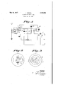
Fig. 1 shows schematically an electron tube and its associated circuits in accordance with the invention,
Fig. 2 is a diagrammatic showing in cross section of another form of-electron tube that may be used in the circuit of Fig. 1, and
Fig. 3 is a further modification.
Referringnow more specifically to Figure 1 which shows the fundamental principle of the arrangement, the electron tube T is shown to comprise a heater M, cathode K, control grid G1, screen grid G2, probe electrode S and anode or plate A. The grid G1 which is-closest to the cathodeK is fed with the incoming alternating voltage from the tuned circuit I. The second or screen grid G2 receives a constant positive potential and is in short-circuited relation with the cathode by the condenser C1. The plate circuit includes an oscillation circuit II which is also tuned to the input frequency. The radio frequency potential set up in this oscillation circuit is fed to the probe electrode S in a suitable manner, say, by a resistance-condenser coupling,
.R, C3. By virtue of the rectifier action there will then be occasioned across the low frequency impedance, resistance R, an audio frequency voltage which may thereafter be impressed upon the next stage, say, by way of a radio frequency filter network, such as F. The audio frequency output terminals are indicated by the letters a and b.
The embodiment hereinbefore disclosed may be varied in variousway whenever electron tubes containing a greater number of grids are used. For instance, there could be used a screen-grid tube furnished with a retarder or suppressor grid. What is here meant by a retarder or suppressor grid is an electrode whose potential is negative in reference to the electrodes previously passed by the current of electrons. Such a retarding grid is mounted, for example, posteriorly of the screen grid, and by regulation of its potential it allows of regulating and influencing the slope of the plate-current characteristic, referred to the potential of the control grid. In this instance, it would be preferable to mount the probe electrode between the screen grid and the retarding grid.
In Figures 2 and 3 are shown certain constructional ways of disposing the probe electrode so that its reaction upon the amplifying system will be as small as possible.
In Figure 2 is shown a tube having a cathode K, a cylindrical control grid G1 and a boxshaped screen-grid G2 as Well as two plate anodes A and A1. The probe electrodes S and S1 are disposed laterally in reference to the plate anodes; the electronic current needed for rectification is so small that the plate current is not appreciably weakened thereby.
In Figure 3 is shown the arrangement of a probe electrode inside a screen-grid tube provided with a retarding or suppressor grid. In this case the probe electrode S is disposed between the screen-grid G2 and the suppressor grid G3, the probe electrode simply consisting of a strip of sheet material positioned parallel to the cathode K and in the plane of the electrode supporting stays, I, 2, I 3, 4. The control action of the various electrodes in the plane of the stays :is disturbed anyway, so that the disposition therein of a probe electrode will not produce any appreciable influence.
What is claimed is:
1. An electron discharge tube comprising a cathode, substantially coextensive grid and anode electrodes cooperating therewith and constituting an amplifier of radio frequency oscillations, and a linear probe electrode interposedin the space between cathode and anode, and arranged in parallel relation to and substantially coextensive with the cathode, said probe electrode adapted to cooperate with the cathode and anode to rectify the amplified radio frequency oscillations.
2. An electron discharge tube comprising a cathode, a signal control grid and a screen grid substantially coextensive with and surrounding the cathode, and amplifier and rectifier anodes substantially coextensive with the aforesaid electrodes disposed one within the other outside the screen grid.
3. An electron discharge tube comprising a cathode, a signal control grid and a screen grid substantially coextensive with and surrounding the cathode, an amplifier anode in the form of a plate disposed outside the screen grid and a rectifier anode in the form of a rod also disposed outside the screen grid but adjacent the amplifier anode and in the electron path between the cathode and said amplifier anode.
4. An electron discharge tube comprising a cathode, a signal control grid and a screen grid surrounding the cathode, an amplifier anode in the form of a cylinder surrounding the screen grid, and a rectifier anode in the form of a narrow metal strip interposed between the screen grid and the amplifier anode.
5. An electron discharge tube comprising a cathode, a signal control grid and a screen grid surrounding the cathode, an amplifier anode in the form of a cylinder surrounding the screen grid, and a rectifier anode in the form of a narrow metal strip interposed between the screen grid and the amplifier anode, support rods for the grids and the amplifier anode all arranged in a common plane, and said rectifier anode being disposed in substantially the plane of electrode support rods.
6. An electron discharge tube for the simultaneous amplification and rectification of high frequency currents comprising a cathode, an anode and a plurality of control electrodes interposed therebetween, said mentioned electrodes being substantially coextensive with said cathode and adapted to amplify high frequency currents, and a probe electrode in the form of a metal strip disposed immediately adjacent said anode. coextensive with and parallel thereto, and cooperating therewith and with the cathode to rectify the amplified high frequency currents.
KARL STEIMEL.
Applications Claiming Priority (1)
| Application Number | Priority Date | Filing Date | Title |
|---|---|---|---|
| DE2080098X | 1933-01-09 |
Publications (1)
| Publication Number | Publication Date |
|---|---|
| US2080098A true US2080098A (en) | 1937-05-11 |
Family
ID=7983937
Family Applications (1)
| Application Number | Title | Priority Date | Filing Date |
|---|---|---|---|
| US703239A Expired - Lifetime US2080098A (en) | 1933-01-09 | 1933-12-20 | Electron discharge tube |
Country Status (1)
| Country | Link |
|---|---|
| US (1) | US2080098A (en) |
-
1933
- 1933-12-20 US US703239A patent/US2080098A/en not_active Expired - Lifetime
Similar Documents
| Publication | Publication Date | Title |
|---|---|---|
| US2547235A (en) | High-frequency amplifier, including a velocity modulation tube | |
| US2080098A (en) | Electron discharge tube | |
| US2202522A (en) | Thermionic valve circuits | |
| US1959010A (en) | Screen grid tube circuit | |
| US2294328A (en) | Ultra-high-frequency signal-translating stage | |
| US2346545A (en) | Electron discharge device circuit | |
| US2067536A (en) | Regenerative receiver arrangement | |
| US2226259A (en) | Amplifier | |
| US2418574A (en) | Electron multiplier | |
| US2156659A (en) | Amplifier device | |
| US2544344A (en) | Audio amplifier circuit with feedback | |
| US2139366A (en) | Electron discharge device | |
| US2052617A (en) | Electron discharge device | |
| US2473754A (en) | Amplifier circuits with double control | |
| US2026944A (en) | Means for receiving and amplifying electric signals | |
| US1955094A (en) | Ultrahigh frequency amplifier | |
| US2094477A (en) | Circuit arrangement for amplifying and/or frequency transformation of electrical oscillations | |
| US1910500A (en) | Radio receiving circuit | |
| US2100769A (en) | Tuning indicator circuits | |
| US2314916A (en) | Circuit for the amplification and/or frequency-transformation of electrical oscillations of ultra high frequency | |
| US1764206A (en) | Electron-tube circuit | |
| US2093560A (en) | Automatic volume control circuit | |
| US2030872A (en) | Ultra-short wave receiver | |
| US1954195A (en) | Vacuum tube | |
| US2009212A (en) | Tuning circuits |