US2075813A - Firing mechanism - Google Patents
Firing mechanism Download PDFInfo
- Publication number
- US2075813A US2075813A US42865A US4286535A US2075813A US 2075813 A US2075813 A US 2075813A US 42865 A US42865 A US 42865A US 4286535 A US4286535 A US 4286535A US 2075813 A US2075813 A US 2075813A
- Authority
- US
- United States
- Prior art keywords
- hammer
- primer
- sear
- container
- case
- Prior art date
- Legal status (The legal status is an assumption and is not a legal conclusion. Google has not performed a legal analysis and makes no representation as to the accuracy of the status listed.)
- Expired - Lifetime
Links
- 238000010304 firing Methods 0.000 title description 5
- 230000000284 resting effect Effects 0.000 description 3
- 239000000725 suspension Substances 0.000 description 2
- 238000010276 construction Methods 0.000 description 1
- 210000005069 ears Anatomy 0.000 description 1
- 230000000717 retained effect Effects 0.000 description 1
Images
Classifications
-
- F—MECHANICAL ENGINEERING; LIGHTING; HEATING; WEAPONS; BLASTING
- F42—AMMUNITION; BLASTING
- F42C—AMMUNITION FUZES; ARMING OR SAFETY MEANS THEREFOR
- F42C7/00—Fuzes actuated by application of a predetermined mechanical force, e.g. tension, torsion, pressure
- F42C7/12—Percussion fuzes of the double-action type, i.e. fuzes cocked and fired in a single movement, e.g. by pulling an incorporated percussion pin or hammer
Definitions
- the ⁇ purpose of the invention is to provide a firing mechanism in which the primer is protected against accidental ring during storage and transportation. This is accomplished by interposing a sear between the primer and hammer and arranging it ⁇ to cock and then release the hammer at the time of firing.
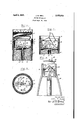
- Fig. 1 is a longitudinal sectional view of aparachute are provided with the improved iiring mechanism and showing the4 parts ⁇ in the safe position.
- Fig. 2 is a similar view showing the parts in firing position.
- Fig. 3 is a sectional view on the line 3 3 of Fig. 1 and Fig. 4 is a longitudinal sectional view showing the invention applied to a bomb.
- a are including a case 5 for an illuminant 6 and a case 1 which is attached to the case 5 by screws 8 and houses a parachute 9.
- the parachute is adapted to be withdrawn from its case in a well known manner when the ilare is launched lfrom an aircraft.
- a disc I0 fitted in the case 5 and spaced from the upper end thereof carries a primer Il which is in line with a relay charge I2 in a central tube I3 that passes through the illuminant.
- a container I4 is inserted in the case 5 andis secured in place by the screws 8.
- the iioor vof the container is formed with punched-out ⁇ feet l5 engaging the disc I0 and has a central opening I6 to expose the primer.
- a pair of upstanding spaced ears Il--ii are also punched out of the floor and carry a pin I3 on which a hammer i9 is pivotally mounted.
- the under side of the hammer is provided with a rlng pin 20 which is adapted to strike the primer.
- A' torsion spring 2l mounted on the pin I8 and bearing on the oor of the container and on the hammer is arranged so that it is not fully compressed until the hammer is moved to cocked position as shown in Fig. 2. n
- a sear 22 is pivotally mounted on the wall of the container and is arranged to cover the primer when resting on the iioorof the container as shown in Fig. 1.
- a cord or wire 23 connects the sear with one of the suspension 'cords 24 of the parachute.
- the cords 24 are fastened to the top of the container i4 and serve to support the iiare when the parachute has' been withdrawn and becomes distended.
- the sear and hammer are in normal safe position when-as shown'j'in Figs-1 the'sear is interposed between the hammer and the primer.
- the distension of the parachute causes the cord 24 to be drawn taut and the cords act through the Wire 23 to rotate the sear as shown in Fig. 2.
- the sear on being raised moves the hammer to cocked position, and thereby compresses the torsion spring. As soon as the sear becomes disengaged from the hammer, the latter is actuated by the spring to re the primer.
- the firing mechanism is applied to a bomb 25.
- An adapter 26 threaded to the interior of the bomb carriesA the primer 21 and a frame 28 resting on the adapter and retained by a tube 29 threaded to the exterior of the bomb, carries the hammer 30 and sear 3
- a case In a projectile, a case, a disc in the case and spaced from the upper end thereof, a primer carried by the disc, a container secured in the upper end of the case above the d isc and having an opening in its door to expose the primer, a pivotally mounted hammer within the container and arranged to strike the primer, a spring for actuating the hammer, a pivotally mounted Sear within the container and normally resting on the ioor of the container between the primer and hammer and covering the primer, and means for rotating the sear to cock and then release the hammer.
Landscapes
- Engineering & Computer Science (AREA)
- General Engineering & Computer Science (AREA)
- Toys (AREA)
Description
J. M. KING FIRIHG MECHANISM Filed sept. so, 1935 April 6, 1937.
Inventur Jahn M Kn Atlnrnev Patented pr. 6, 1937 John M. King, Dover, N. J.
Application September 30,' 1935, Serial No. 42,865
y(Granted under the act of March 3, 1883, as
amended April 30,
The` purpose of the invention is to provide a firing mechanism in which the primer is protected against accidental ring during storage and transportation. This is accomplished by interposing a sear between the primer and hammer and arranging it` to cock and then release the hammer at the time of firing.
To these and other ends, the invention .con-
sists in the construction, arrangement and com- ,bination of elements described hereinafter and pointed out in the claim forming a part of this specication.
A practical embodiment of the invention is illustrated in the accompanying drawing, wherein:
Fig. 1 is a longitudinal sectional view of aparachute are provided with the improved iiring mechanism and showing the4 parts `in the safe position.
Fig. 2 is a similar view showing the parts in firing position.
Fig. 3 is a sectional view on the line 3 3 of Fig. 1 and Fig. 4 is a longitudinal sectional view showing the invention applied to a bomb.
Referring to Figs. 1 and 3 there is shown a are including a case 5 for an illuminant 6 and a case 1 which is attached to the case 5 by screws 8 and houses a parachute 9. The parachute is adapted to be withdrawn from its case in a well known manner when the ilare is launched lfrom an aircraft.
A disc I0 fitted in the case 5 and spaced from the upper end thereof carries a primer Il which is in line with a relay charge I2 in a central tube I3 that passes through the illuminant.
A container I4 is inserted in the case 5 andis secured in place by the screws 8. The iioor vof the container is formed with punched-out `feet l5 engaging the disc I0 and has a central opening I6 to expose the primer. A pair of upstanding spaced ears Il--ii are also punched out of the floor and carry a pin I3 on which a hammer i9 is pivotally mounted. The under side of the hammer is provided with a rlng pin 20 which is adapted to strike the primer. A' torsion spring 2l mounted on the pin I8 and bearing on the oor of the container and on the hammer is arranged so that it is not fully compressed until the hammer is moved to cocked position as shown in Fig. 2. n
A sear 22 is pivotally mounted on the wall of the container and is arranged to cover the primer when resting on the iioorof the container as shown in Fig. 1. A cord or wire 23 connects the sear with one of the suspension 'cords 24 of the parachute. The cords 24 are fastened to the top of the container i4 and serve to support the iiare when the parachute has' been withdrawn and becomes distended.
The sear and hammer are in normal safe position when-as shown'j'in Figs-1 the'sear is interposed between the hammer and the primer. The distension of the parachute causes the cord 24 to be drawn taut and the cords act through the Wire 23 to rotate the sear as shown in Fig. 2. The sear on being raised moves the hammer to cocked position, and thereby compresses the torsion spring. As soon as the sear becomes disengaged from the hammer, the latter is actuated by the spring to re the primer.
In the modication shown in Fig. 4 the firing mechanism is applied to a bomb 25. An adapter 26 threaded to the interior of the bomb carriesA the primer 21 and a frame 28 resting on the adapter and retained by a tube 29 threaded to the exterior of the bomb, carries the hammer 30 and sear 3|. A wire 32 connects the sear and a cover 33 and has its upper end terminating in a loop 34 for attachment of the suspension cord 35 of the parachute (not shown). When the parachute opens, the cover is removed and the sear actuated in the manner previously described.
I claim:
In a projectile, a case, a disc in the case and spaced from the upper end thereof, a primer carried by the disc, a container secured in the upper end of the case above the d isc and having an opening in its door to expose the primer, a pivotally mounted hammer within the container and arranged to strike the primer, a spring for actuating the hammer, a pivotally mounted Sear within the container and normally resting on the ioor of the container between the primer and hammer and covering the primer, and means for rotating the sear to cock and then release the hammer.
JOHN M. KING.
Priority Applications (1)
| Application Number | Priority Date | Filing Date | Title |
|---|---|---|---|
| US42865A US2075813A (en) | 1935-09-30 | 1935-09-30 | Firing mechanism |
Applications Claiming Priority (1)
| Application Number | Priority Date | Filing Date | Title |
|---|---|---|---|
| US42865A US2075813A (en) | 1935-09-30 | 1935-09-30 | Firing mechanism |
Publications (1)
| Publication Number | Publication Date |
|---|---|
| US2075813A true US2075813A (en) | 1937-04-06 |
Family
ID=21924154
Family Applications (1)
| Application Number | Title | Priority Date | Filing Date |
|---|---|---|---|
| US42865A Expired - Lifetime US2075813A (en) | 1935-09-30 | 1935-09-30 | Firing mechanism |
Country Status (1)
| Country | Link |
|---|---|
| US (1) | US2075813A (en) |
Cited By (7)
| Publication number | Priority date | Publication date | Assignee | Title |
|---|---|---|---|---|
| US2547820A (en) * | 1945-12-29 | 1951-04-03 | Gustaf W Hammar | Fuse and igniter |
| US2889653A (en) * | 1952-07-29 | 1959-06-09 | Kilgore Inc | Firing mechanism |
| US2961962A (en) * | 1945-01-19 | 1960-11-29 | Leonard D Jackson | Trip-wire flare |
| US3020845A (en) * | 1960-11-04 | 1962-02-13 | Jules M Hardesty | Temperature responsive firing mechanism |
| US3260206A (en) * | 1963-02-13 | 1966-07-12 | Rinker Fa R | Detonator |
| US3762327A (en) * | 1970-05-04 | 1973-10-02 | Pains Wessex Ltd | Pyrotechnic devices |
| US4192236A (en) * | 1976-03-04 | 1980-03-11 | Wallop Industries Limited | Firing mechanism for percussion caps |
-
1935
- 1935-09-30 US US42865A patent/US2075813A/en not_active Expired - Lifetime
Cited By (7)
| Publication number | Priority date | Publication date | Assignee | Title |
|---|---|---|---|---|
| US2961962A (en) * | 1945-01-19 | 1960-11-29 | Leonard D Jackson | Trip-wire flare |
| US2547820A (en) * | 1945-12-29 | 1951-04-03 | Gustaf W Hammar | Fuse and igniter |
| US2889653A (en) * | 1952-07-29 | 1959-06-09 | Kilgore Inc | Firing mechanism |
| US3020845A (en) * | 1960-11-04 | 1962-02-13 | Jules M Hardesty | Temperature responsive firing mechanism |
| US3260206A (en) * | 1963-02-13 | 1966-07-12 | Rinker Fa R | Detonator |
| US3762327A (en) * | 1970-05-04 | 1973-10-02 | Pains Wessex Ltd | Pyrotechnic devices |
| US4192236A (en) * | 1976-03-04 | 1980-03-11 | Wallop Industries Limited | Firing mechanism for percussion caps |
Similar Documents
| Publication | Publication Date | Title |
|---|---|---|
| US2447972A (en) | Target balloon | |
| US2075813A (en) | Firing mechanism | |
| US2732245A (en) | lemoigne | |
| US2857842A (en) | Land mine | |
| US1318926A (en) | settle | |
| US3371578A (en) | Rocket launchers | |
| US2422839A (en) | Release coupling for parachutes | |
| US3122059A (en) | Rocket launchers | |
| US1277892A (en) | Safety device for aeroplanes. | |
| US2918869A (en) | Gyroscope driving means | |
| US2328208A (en) | Indicator | |
| US2966849A (en) | Submarine signalling device | |
| US2422548A (en) | Detonating mechanism | |
| US1640892A (en) | Pyrotechnic signal | |
| US2473597A (en) | Bomb shackle and release | |
| US2935949A (en) | Combination mine fuze | |
| US2440702A (en) | Antipersonnel mine | |
| US2101071A (en) | Grenade | |
| US1303976A (en) | Airship attachment | |
| US2036279A (en) | Auxiliary parachute | |
| US2949274A (en) | Control head | |
| US2358647A (en) | Hand grenade | |
| US3208347A (en) | Rocket launchers and rear sight therefor | |
| US2400002A (en) | Fuse | |
| US1052606A (en) | Bomb for use with aeroplanes and other flying-machines. |