US2068898A - Circuit controlling apparatus - Google Patents
Circuit controlling apparatus Download PDFInfo
- Publication number
- US2068898A US2068898A US711378A US71137834A US2068898A US 2068898 A US2068898 A US 2068898A US 711378 A US711378 A US 711378A US 71137834 A US71137834 A US 71137834A US 2068898 A US2068898 A US 2068898A
- Authority
- US
- United States
- Prior art keywords
- brushes
- disk
- bolt
- contact
- bus bar
- Prior art date
- Legal status (The legal status is an assumption and is not a legal conclusion. Google has not performed a legal analysis and makes no representation as to the accuracy of the status listed.)
- Expired - Lifetime
Links
- 230000033001 locomotion Effects 0.000 description 18
- 230000000694 effects Effects 0.000 description 6
- 230000008933 bodily movement Effects 0.000 description 2
- 238000010276 construction Methods 0.000 description 2
- 241000239290 Araneae Species 0.000 description 1
- 241001527902 Aratus Species 0.000 description 1
- 241000283984 Rodentia Species 0.000 description 1
- 230000003292 diminished effect Effects 0.000 description 1
- 210000005069 ears Anatomy 0.000 description 1
- 230000005484 gravity Effects 0.000 description 1
- 239000011810 insulating material Substances 0.000 description 1
- 230000002452 interceptive effect Effects 0.000 description 1
- 230000001788 irregular Effects 0.000 description 1
- 230000010355 oscillation Effects 0.000 description 1
- 229920000136 polysorbate Polymers 0.000 description 1
- VLPFTAMPNXLGLX-UHFFFAOYSA-N trioctanoin Chemical compound CCCCCCCC(=O)OCC(OC(=O)CCCCCCC)COC(=O)CCCCCCC VLPFTAMPNXLGLX-UHFFFAOYSA-N 0.000 description 1
Images


Classifications
-
- H—ELECTRICITY
- H01—ELECTRIC ELEMENTS
- H01H—ELECTRIC SWITCHES; RELAYS; SELECTORS; EMERGENCY PROTECTIVE DEVICES
- H01H3/00—Mechanisms for operating contacts
- H01H3/22—Power arrangements internal to the switch for operating the driving mechanism
- H01H3/26—Power arrangements internal to the switch for operating the driving mechanism using dynamo-electric motor
-
- Y—GENERAL TAGGING OF NEW TECHNOLOGICAL DEVELOPMENTS; GENERAL TAGGING OF CROSS-SECTIONAL TECHNOLOGIES SPANNING OVER SEVERAL SECTIONS OF THE IPC; TECHNICAL SUBJECTS COVERED BY FORMER USPC CROSS-REFERENCE ART COLLECTIONS [XRACs] AND DIGESTS
- Y10—TECHNICAL SUBJECTS COVERED BY FORMER USPC
- Y10T—TECHNICAL SUBJECTS COVERED BY FORMER US CLASSIFICATION
- Y10T74/00—Machine element or mechanism
- Y10T74/15—Intermittent grip type mechanical movement
- Y10T74/1503—Rotary to intermittent unidirectional motion
- Y10T74/1508—Rotary crank or eccentric drive
-
- Y—GENERAL TAGGING OF NEW TECHNOLOGICAL DEVELOPMENTS; GENERAL TAGGING OF CROSS-SECTIONAL TECHNOLOGIES SPANNING OVER SEVERAL SECTIONS OF THE IPC; TECHNICAL SUBJECTS COVERED BY FORMER USPC CROSS-REFERENCE ART COLLECTIONS [XRACs] AND DIGESTS
- Y10—TECHNICAL SUBJECTS COVERED BY FORMER USPC
- Y10T—TECHNICAL SUBJECTS COVERED BY FORMER US CLASSIFICATION
- Y10T74/00—Machine element or mechanism
- Y10T74/15—Intermittent grip type mechanical movement
- Y10T74/1558—Grip units and features
- Y10T74/1577—Gripper mountings, lever
- Y10T74/1579—Reversible
Definitions
- This invention relates to circuit controlling the pin or shaft 33 constituting the common cen apparatus of that character in which a movable ter ior the circularly arranged. contact memcontact member is moved step by step in oppobers I2 and the bus bar 14. site directions to be engaged with stationary com
- the movable contact member is composed of tact members or terminal blocks, with which are two laminated brushes IE3, ii, arranged to have 5 connected storage battery or like cells, which are the opposite ends of each brush engaged with the designed to be added to or cut out of a circuit bus bar it and with a stationary contact memwhose strength of current is to be increased or ber l2, whereby a maximum and equal contact diminished to meet conditions of use.
- the invention has for its object to provide a tionary contact members may be obtained. simple, efiicient and superior apparatus as will Another object of the present invention is to be described. automatically compensate for wear at the ends The particular features of the invention will of the brushes and thereby maintain the maxi be pointed out in the claims at the end of this mum contact under conditions of use and equal 5 specification. ize the resistance at the surfaces in contact and In the accompanying drawings, minimize the heat at the contact surfaces.
- Fig. 1 is a front elevation with parts in secthis end provision is made whereby the brushes tion, of one form of circuit controlling apparatus have a floating relation to the oscillating carrierembodying this invention, the section being taken for said brushes, so that they may move in a on the line l-l, Fig. 2; plane transversely of the path in which they are 20 Fig. 2, a section on the line 2-2, Fig. 1; moved by the oscillating carrier.
- Fig. 3 a front elevation on a larger scale of In the present instance the brushes Hi, I! are the movable brush-carrying member shown in moved in a circular path to establish electrical Fig. 1; connection between the bus bar [4 and one of the Fig. 4, a side elevation of Fig. 3 with the individual stationary contact members l2, and 25 brushes and a part of their carrier shown in secare also capable of movement in a plane transtion, the latter being taken on the line 4-4, versely of or radially with relation to said circu- Fig. 3; lar path, which enables the opposite ends of the Fig. 5, a section on the line 55, Fig. 3; brushes to adjust themselves with relation to the Fig.
- the invention is illusas I! fastened to it to move therewith, while the trated in a circuit-controlling apparatus of the other brush it is loosely mounted on the bolt 20 40 type shown and described in U. S. Patent No. to enable the brush l6 and the bolt to be moved 996,960 dated July 4, 1911 and is an improvewith relation to each other.
- the brush I? is ment thereon as will be described. clamped on the bolt 20 between a plate or member In the apparatus herein shown, a plurality of 22 and a head 23 on the bolt and is secured in individual stationary contact members or terfixed relation to the bolt by screws 24 extending 45 minal blocks l2 are arranged to form part of a through the head 23 and the brush i!
- This arrangement provides for adjustment of the brushes I 6, I! from one side of the stationary contact members 12 and of the bus bar M, whichever side is more accessible, without removing the brushes from their oscillating carrier.
- the transverse movement of the brush unit I B, 25, 26 on the bolt 20 permits both ends of the brush IE to compensate for any irregular contact at either end of the brush l6, due to uneven wear or other irregularities which may arise, as the brush it may automatically adjust itself to compensate for such irregularity and thereby provide for equal and uniform contact at each end of the brush it and thus ensure equal distribution of current from the bus bar l4 to the stationary contact member l2 with which the brush I6 is engaged.
- the brush IT is also capable of automatically compensating for irregularities by reason of the loose connection between the bolt 20 and the brush H5.
- the brushes l6, ll are designed to be moved as a unit from one stationary contact I2 to another, and to this end, they are connected with an 0s cillatory or reciprocating carrier, which connection is effected as herein shown by a spider or device having a hub 32 located between the brushes l6, H in the space 33 between the bus bar #4 and the stationary contact members H2.
- the hub 32 is loosely mounted upon the bolt 20 so that the bolt may slide through the hub 32 when the brush I1 is adjusted to the bus bar 14 and contact members 2.
- the hub 32 has attached to it two pairs of arms 34, 35 located on opposite sides of the brushes 16, H and said arms are preferably constructed so as to obtain a very slight clearance at the ends of the arms and a materially greater clearance intermediate the said ends as clearly shown in Figs. 3 and 5.
- each of the arms 34, 35 is provided at its opposite ends with inwardly extended portions 36 of sufiicient area to obtain a substantial bearing against the brush with which it cooperates, while at the same time reducing the area of contact of the arms with the brushes and thereby avoid interference of the arms with the movement of the brushes, when the latter are manually or automatically adjusted to the bus bar l4 and stationary contact members l2.
- the arms 34, 35 may be designated as pusher arms, as they function to push or move bodily the brushes IS, I! as a unit from one stationary contact l2 to another.
- the bodily movement of the brushes IE, IT by the pusher arms 34, 35 may be effected by an oscillating device, which in the present instance consists of a lever 40 provided with a hub 4
- the lever 4%) is provided at its upper end with forks 42, 43, to which the hub 32 is fastened by screw bolts (see Figs. 3 and 5), or it may be fastened in any other suitable manner.
- the lever 40 is oscillated by means of pawls 46, 41 (see Fig. 1) pivotally mounted on the lever 40 and cooperating with teeth 48 on the periphery of a disk 49 provided with a hub 50 which is loosely mounted on the center pin or shaft 13 (see Fig. 2).
- the teeth 48 extend transversely of the disk 49 and have co-operating with them a cam ring 52 carried by the disk 49 and movable on the disk in an annular guideway 54, formed by a reduced portion of the disk at one side thereof and a retaining ring 55 which is secured to the side of the disk 49 by screws 56 (see Figs. 6 and 7).
- the cam ring 52 is provided with oppositely inclined portions 58, 55 which constitute cams and co-operate with the toothed disk 49 to permit the pawl 46 or 4! to engage a tooth of the disk 43 in one position of the cam ring 52 with relation to the toothed disk 49, and to prevent such engagement of the pawl 46 or 4! with a tooth in another position of the cam ring 52 with relation to the toothed disk 49.
- toothed disk 49 acts as a driver or mover for the oscillating lever 48, and moves the same and the brushes carried thereby in the proper direction to effect the desired change in the circuit in which the brushes are included.
- the toothed disk 49 may be moved by hand or by power. To move it by power the toothed disk 49 is connected with an electric motor (see Fig. 1) having its armature shaft 62 provided with a worm 64, which meshes with and drives a worm gear 6% fast on a shaft 68 and having a crank thereon connected with a crank pin 12 on the disk 49 by a connecting rod 3. The toothed disk 49 is moved in the direction indicated by the arrow 74, Fig.
- the disk 451 may be manually moved by a crank or handle H4 which is removably engaged with the end of the shaft 68 of the worm gear.
- the connecting rod 73 is made adjustable so that the teeth of the disk 49 may be adjusted or properly positioned with relation to the cams 58, 59 of the cam ring 52 and enable the contact brushes Ni, ii to be centrally located with relation to the sides of the stationary contact member l2 with which they are engaged when they come to rest.
- the adjustable connecting rod 73 is preferably made as shown in Fig. 9 and consists of a member '16 for engaging the stud 72 on the disk 49, a like member '18 for engaging the stud it on the worm gear 66, and a threaded rod 8E1 for engaging threaded sockets in the members 76, 7B.
- the threaded rod 88 is provided with a collar 8
- the socketed ends of the members I6, I8 are split lengthwise to be compressed by the screws 82 and thereby secure the threaded rod 88 and the members I6, I8 in fixed relation in their adjusted position.
- the teeth 48 on the disk 49 are arranged in two opposing sets (see Fig. 6), which may be designated the right and left sets, and the cam ring 52 is arranged with relation to the disk 49, so that the teeth of the right set are uncovered by the cams 58 to permit the pawl 48 to be engaged with the teeth constituting the right set; and so that the teeth of the left set are covered by the cams 59 cooperating therewith so as to prevent the teeth of the left set being engaged by the pawl 41 (see Fig. 1) at the same time.
- the teeth 48 of the right set cooperate with the pawl 46 to turn the lever 48 toward the left viewing Fig. 1, and thereby move the contact brushes toward the left, from one contact member I2 to the next adjacent contact member I2, when it is desired to remove or cut out a cell from the circuit.
- the teeth 48 of the left set cooperate with the pawl 41 to turn the lever 48 toward the right and move the brushes onto the next contact member l2 toward the right when a cell is to be added to the circuit.
- cam bar 86 (see Figs. 1 and 6) provided with side flanges 81, which slide in a guideway in a guide 88 affixed to the toothed disk 49.
- the cam bar 86 is provided on its opposite sides with inclined surfaces 89, 98, which constitute cams and cooperate with rollers 9i, 92 carried by the cam ring 52.
- the cam bar 86 is reciprocated between the rollers 9
- the cam 98 On the down stroke of the cam bar 86 in the direction opposite to that indicated by the arrow 93, the cam 98, which at such time is above the roller 92, engages the latter and moves or rotates the cam ring 52 in the direction opposite to the arrow 94, so as to lift the pawl 41, cover the teeth of the left set and uncover the teeth of the right set.
- a preferred construction of locking means is herein shown (see Fig. 6), which consists of a pin or bolt 96 slidable in an opening 91 in one of the side bars of the guide 88 and actuated by a spring 98 to enter a socket or notch 99 in a side flange 81 of the cam bar when the latter is in its elevated position.
- the inner end of the locking pin or bolt 96 is substantially V-shaped, as is also the socket or notch 99, so that when the bolt is entered into the socket 99, the cam bar will be locked in its elevated position against release by vibration but will be unlocked by positive movement of the cam bar downward, which movement may be effected as herein shown by manual operation or automatically as will be described.
- the cam bar may also be locked in its lowered position, shown in Fig. 6, by providing the flange 8'! of said bar with a second notch I98 with which the bolt or pin 99 co-operates.
- the cam bar 86 is moved into its extreme upward position by an electromagnet or solenoid I88 and is moved into its lowered position by a solenoid I8I (see Fig. 2), which solenoids are opposed to each other and have a common armature or core 182 provided with an adjustable connecting rod composed of the members I83, I84.
- the member 13 has a ball and socket connection with the armature I82 and has its upper end screw-threaded to enter a threaded socket in the lower end of the member I84.
- the upper end of the member I84 is pivotally connected with the cam bar 88.
- the cam bar 86 may also be moved manually by means of a lever H8 pivoted at M2 to the framework of the apparatus and having its inner end forked to extend into slots H4 in ears H5, which are shown in Fig. 1 and are extended from opposite sides of the link member I94.
- the apparatus above described is designed among other uses to be employed as an end cell switch in power houses and like stations, where it is desired to add storage battery cells to increase the voltage on the line or to diminish the same as the case may be when the situation arises.
- the stationary contact members 22 are mounted on a panel or board E28 of insulating material, and each contact member is provided with a stud I21, which is extended through the panel or board I28 and has fastened thereon a terminal socket member I22 for connection with a battery cell (not shown).
- the bus bar I4 is also provided with a like stud I24 extended through the panel or board I28 and provided with a socket member I25 for connection with one side of the line or circuit in which the battery cells are to be included or removed therefrom.
- the oscillating member or lever 49 is held stationary when the movable contact brushes I6, 2; are in their central position with relation to the stationary contact member 52 which is connected with the storage battery cell last added to the circuit.
- This result is effected by a brake band I26 co-operating with a brake drum I2! on the armature shaft 62 of the motor 68, which brake band is applied to the brake drum i2! by a suitable spring (not shown), and is released by an electromagnet I28 when the latter is energized.
- the motor 68 and the brake magnet I28 may be controlled and operated substantiallyas de-, scribed in the patent above referred to.
- the electromagnets or solenoids I80, I01 which control the movements of the cam ring 52 may be controlled by a suitable switch not shown, and are responsive to the condition of the circuit in which the apparatus is included, so as to energize the solenoids and shift the cam ring for- Ward or backward according to Whether a cell is to be added to the working circuit or taken out thereof.
- the solenoid Hi9 is energized and the cam bar 86 is lifted so as to shift the cam ring 52 in the direction indicated by the arrow St in Fig. 6 and thereby cover the right set of teeth #8 on the toothed disk 49 and at the same time uncover the left set of teeth.
- the solenoid Hll is energized and the cam bar 86 is lowered so as to shift the cam ring 52 in the direction opposite to that indicated by the arrow 94, and thereby cover the left set of teeth 48 and uncover the right set of teeth, which is the condition represented in Figs. 1 and 6.
- the brake magnet 128 is energized to release the brake band, and the circuit of the motor 66 is closed.
- the motor 6 rotates the toothed disk 49 to the right, Fig. 1, on the forward throw of the connecting rod 73 in the direction of the arrow M, Figs. 1 and 6, and on such movement, the pawl 47 is lifted by the cams 59 and the toothed disk 49 clicks by the pawl 46.
- circuit controllers I32, I33 are affixed to the panel or board M6 at opposite ends of the bus bar I4 and in the path of movement of the oscillating lever 35, so as to be opened by the lever 40 when the latter is moved into its extreme positions to the right and left, with the brushes 58, i? in the center of either of the end contact members l2.
- the movable parts of the apparatus may be protected by a box or casing I40 which is suitably secured to the panel or board I 20, and is provided in its front surface with a. slot I42 which is curved and has the same center as the oscillating lever M3 and is of sufilcient length to display all of the stationary contact members [2 and enable a pointer or index M i to be seen by the operator.
- the pointer or index M4 is secured to the oscillating lever 40 to move therewith.
- an oscillating lever in combination, an oscillating lever, a shaft onwhich said lever is mounted, a contact member carried by said lever, a rotatable disk mounted on said shaft and provided with sets of oppositely arranged teeth, a ring loosely mounted on said toothed disk to be rotated thereon and provided with sets of cams co-operating with the sets of teeth on said disk to cover and uncover said sets of teeth, pawls carried by said oscillating lever and co-operating with said toothed disk to effect movement of said lever in opposite di rections by rotation of said toothed disk, a cam bar mounted on said toothed disk to move substantially radially thereon and co-operating with said toothed disk to be rotated thereon and pro vided with sets of cams co-operating with the sets of teeth on said disk to cover and uncover said sets of teeth, pawls carried by said oscillating lever and co-operating with said toothed disk to effect movement of said lever in opposite directions by rotation of said toothed disk,
- a bus bar a. plurality of stationary contact members arranged in a circle and spaced from said bus bar, contact brushes located on opposite sides of said stationary contact members and said bus bar and having their opposite ends adapted to contact with said bus bar and said contact members, a bolt connecting said brushes and upon which one of said brushes is loosely mounted to slide thereon, an oscillating lever, a hub carried by said lever and through which said bolt is extended to slide therein, said hub having members co-operating with said brushes to move the same bodily in a circular path and between which said brushes are movable in a direction transversely of said circular path, and means for oscillating said lever.
- an oscillating lever provided with forks, a hub located between and secured to said forks, a bolt loosely extended through said hub, contact brushes mounted on said bolt and individually movable toward and from said hub, and pusher arms for engaging the opposite sides of said brushes to effect bodily movement of said brushes as a unit.
- a plurality of stationary contact members in combination, a bus bar spaced therefrom, contact brushes co-operating with said bus bar and said stationary contact members on opposite sides thereof, a bolt secured to one of said brushes and upon which the other of said brushes is mounted to move thereon, and means on said bolt for adjusting the pressure of both of said brushes against said bus bar and said contact members.
- a plurality of stationary contact members in combination, a plurality of stationary contact members, a bus bar spaced therefrom, a bolt extended transversely of said contact members and said bus bar between the same, contact brushes mounted on said bolt on opposite sides of said contact members and said bus bar, one of said contact members being loosely mounted on said bolt to move lengthwise thereof, means on said bolt cooperating with one of said brushes to effect simultaneous movement of said brushes toward each other and into contact with the opposite surfaces of said bus bar and contact members, and a reciprocating carrier through which said bolt is loosely extended.
- a plurality of stationary contact members in combination, a plurality of stationary contact members, a bus bar spaced therefrom, contact brushes co-operating with said bus bar and said contact members on opposite sides thereof, a supporting member upon; which said contact brushes are mounted, one of said contact brushes being loosely mounted on said supporting member to move lengthwise thereof, a reciprocating carrier through which said supporting member is loosely extended to move transversely of the path in which the said carrier is reciprocated, and means on said supporting member co-operating with one of said brushes to move it in one direction toward the path in which said carrier is reciprocated and to simultaneously move the other of said brushes in the opposite direction toward said path, whereby the pressure of the brushes against the bus bar and said contact members at the end of the brushes is equalized.
Landscapes
- Brushes (AREA)
Description
Jan. 26, 1937. A. E. ANDERSON 2,068,898
CIRCUIT CONTROLLING APPARATUS Filed Feb. 15, 1934 4 Sheets-Sheet 1 IN VENTOR.
y BY flaw A TTORNEY.
Jan. 26, 1937. A. E. ANDERSON CIRCUIT CONTROLLING APPARATUS Filed Feb. 15, 1934 4 Sheets-Sheet 2 ATTORNEY.
Jan. 26, 1937. A. E. ANDERSON 2,063,898
CIRCUIT CONTROLLING APPARATUS Filed Feb. 15, 1954 I 4 Sheets-Sheet 3 if 'n Fly-5 HQ"?! INVENTOR.
ATTORNEY.
Jan. 26, 1937. A. E. ANDERSON 2,063,893
CIRCUIT CONTROLLING APPARATUS Filed Feb. 15, 1934 4 Sheets-Sheet 4 ATTORNEY Patented Jan. 26, 1937 UNITED STATES PATENT ()FFICE CIRCUET CDY'QTEQLLING AYE- ARATUS Alf E. Anderson, Milton, Mass.
Application February 15, 1934, Serial No. 711,378
'7 Claims. (Cl. 200-17) This invention relates to circuit controlling the pin or shaft 33 constituting the common cen apparatus of that character in which a movable ter ior the circularly arranged. contact memcontact member is moved step by step in oppobers I2 and the bus bar 14. site directions to be engaged with stationary com The movable contact member is composed of tact members or terminal blocks, with which are two laminated brushes IE3, ii, arranged to have 5 connected storage battery or like cells, which are the opposite ends of each brush engaged with the designed to be added to or cut out of a circuit bus bar it and with a stationary contact memwhose strength of current is to be increased or ber l2, whereby a maximum and equal contact diminished to meet conditions of use. between the brushes and the bus bar and its 0 The invention has for its object to provide a tionary contact members may be obtained. simple, efiicient and superior apparatus as will Another object of the present invention is to be described. automatically compensate for wear at the ends The particular features of the invention will of the brushes and thereby maintain the maxi be pointed out in the claims at the end of this mum contact under conditions of use and equal 5 specification. ize the resistance at the surfaces in contact and In the accompanying drawings, minimize the heat at the contact surfaces. To
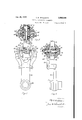
Fig. 1 is a front elevation with parts in secthis end provision is made whereby the brushes tion, of one form of circuit controlling apparatus have a floating relation to the oscillating carrierembodying this invention, the section being taken for said brushes, so that they may move in a on the line l-l, Fig. 2; plane transversely of the path in which they are 20 Fig. 2, a section on the line 2-2, Fig. 1; moved by the oscillating carrier.
Fig. 3, a front elevation on a larger scale of In the present instance the brushes Hi, I! are the movable brush-carrying member shown in moved in a circular path to establish electrical Fig. 1; connection between the bus bar [4 and one of the Fig. 4, a side elevation of Fig. 3 with the individual stationary contact members l2, and 25 brushes and a part of their carrier shown in secare also capable of movement in a plane transtion, the latter being taken on the line 4-4, versely of or radially with relation to said circu- Fig. 3; lar path, which enables the opposite ends of the Fig. 5, a section on the line 55, Fig. 3; brushes to adjust themselves with relation to the Fig. 6, an elevation on an enlarged scale of the bus bar and stationary contact members inde- 30 oscillating disk shown in Fig. 1, which effects pendently of the oscillating carrier. This floating oscillation of the brush-carrying member; connection of the contact brushes l6, ll with Fig. 7, a side elevation and section of the disk their carrier may and preferably will be obtained and attached parts shown in Fig. 6; by providing a loose mechanical connection be- Fig. 8, an enlarged detail in section on the line tween the brushes and their carrier, and such 35 8-8, Fig. 6; and connection may be obtained as will now be de- Fig. 9, an enlarged detail of the adjustable link scribed. To this end a bolt or spindle 2%, shown shown in Fig. l and which will be referred to. best in Figs. 3, 4 and 5, has one of the brushes,
In the present instance, the invention is illusas I! fastened to it to move therewith, while the trated in a circuit-controlling apparatus of the other brush it is loosely mounted on the bolt 20 40 type shown and described in U. S. Patent No. to enable the brush l6 and the bolt to be moved 996,960 dated July 4, 1911 and is an improvewith relation to each other. The brush I? is ment thereon as will be described. clamped on the bolt 20 between a plate or member In the apparatus herein shown, a plurality of 22 and a head 23 on the bolt and is secured in individual stationary contact members or terfixed relation to the bolt by screws 24 extending 45 minal blocks l2 are arranged to form part of a through the head 23 and the brush i! into the circle having the center [3, which also constitutes plate 22. The brush I6 is secured in fixed relation the center for a curved bus bar M of smaller rato an inner plate 25 and an outer plate 26 by dius than that of the circle in which the indiscrews 21, and said brush it and its clamping vidual stationary contact members 12 are located. plates 25, 26 are mounted as a unit on the bolt 50 The bus bar I and the stationary contact 2!! and are provided with holes 28 of larger diammembers [2 have co-operating with them a moveter than the bolt, so that the brush l8 and its able contact member of a novel construction as clamping plates may be moved as a unit longituwill be described and which is associated with an inally of and transversely with relation to the oscillating carrier which is loosely mounted on bolt. The movement of the brush unit length- 55 wise of the bolt 20 may be effected by adjusting nuts 30 on the free end of the bolt which cooperate with the outer clamping plate 26 of said unit.
This arrangement provides for adjustment of the brushes I 6, I! from one side of the stationary contact members 12 and of the bus bar M, whichever side is more accessible, without removing the brushes from their oscillating carrier.
The transverse movement of the brush unit I B, 25, 26 on the bolt 20 permits both ends of the brush IE to compensate for any irregular contact at either end of the brush l6, due to uneven wear or other irregularities which may arise, as the brush it may automatically adjust itself to compensate for such irregularity and thereby provide for equal and uniform contact at each end of the brush it and thus ensure equal distribution of current from the bus bar l4 to the stationary contact member l2 with which the brush I6 is engaged. The brush IT is also capable of automatically compensating for irregularities by reason of the loose connection between the bolt 20 and the brush H5.
The brushes l6, ll are designed to be moved as a unit from one stationary contact I2 to another, and to this end, they are connected with an 0s cillatory or reciprocating carrier, which connection is effected as herein shown by a spider or device having a hub 32 located between the brushes l6, H in the space 33 between the bus bar # 4 and the stationary contact members H2. The hub 32 is loosely mounted upon the bolt 20 so that the bolt may slide through the hub 32 when the brush I1 is adjusted to the bus bar 14 and contact members 2. The hub 32 has attached to it two pairs of arms 34, 35 located on opposite sides of the brushes 16, H and said arms are preferably constructed so as to obtain a very slight clearance at the ends of the arms and a materially greater clearance intermediate the said ends as clearly shown in Figs. 3 and 5.
To this end each of the arms 34, 35 is provided at its opposite ends with inwardly extended portions 36 of sufiicient area to obtain a substantial bearing against the brush with which it cooperates, while at the same time reducing the area of contact of the arms with the brushes and thereby avoid interference of the arms with the movement of the brushes, when the latter are manually or automatically adjusted to the bus bar l4 and stationary contact members l2.
For sake of clearness, the arms 34, 35 may be designated as pusher arms, as they function to push or move bodily the brushes IS, I! as a unit from one stationary contact l2 to another.
It will be understood that a pair of pusher arms 34, 35 cooperates with each of the brushes IS, IT, as clearly shown in Fig. 5.
The bodily movement of the brushes IE, IT by the pusher arms 34, 35, may be effected by an oscillating device, which in the present instance consists of a lever 40 provided with a hub 4|, which is loosely mounted to turn on the shaft or pin 13, (see Fig. 1). The lever 4%) is provided at its upper end with forks 42, 43, to which the hub 32 is fastened by screw bolts (see Figs. 3 and 5), or it may be fastened in any other suitable manner.
In the present instance, the lever 40 is oscillated by means of pawls 46, 41 (see Fig. 1) pivotally mounted on the lever 40 and cooperating with teeth 48 on the periphery of a disk 49 provided with a hub 50 which is loosely mounted on the center pin or shaft 13 (see Fig. 2). The teeth 48 extend transversely of the disk 49 and have co-operating with them a cam ring 52 carried by the disk 49 and movable on the disk in an annular guideway 54, formed by a reduced portion of the disk at one side thereof and a retaining ring 55 which is secured to the side of the disk 49 by screws 56 (see Figs. 6 and 7).
The cam ring 52 is provided with oppositely inclined portions 58, 55 which constitute cams and co-operate with the toothed disk 49 to permit the pawl 46 or 4! to engage a tooth of the disk 43 in one position of the cam ring 52 with relation to the toothed disk 49, and to prevent such engagement of the pawl 46 or 4! with a tooth in another position of the cam ring 52 with relation to the toothed disk 49. By reference to Fig. 6, it will be observed that the portion of the cam ring 52 between adjacent cams 58, 59 projects above the circumference of the toothed disk 49, so that when the cam ring 52 is rotated on the disk 4Q into a position wherein the low part of the cams are in line with a tooth 48 on the disk 49, the pawl co-operating with such tooth can engage the tooth and be moved by rotation of the disk 49 the distance of one tooth, which allows the toothed disk 49 to move the brush-carrying lever 46 in the proper direction to move the brushes I6, I? from one stationary contact member i2 to the next adjacent contact member l2.
It will thus be observed that the toothed disk 49 acts as a driver or mover for the oscillating lever 48, and moves the same and the brushes carried thereby in the proper direction to effect the desired change in the circuit in which the brushes are included.
The toothed disk 49 may be moved by hand or by power. To move it by power the toothed disk 49 is connected with an electric motor (see Fig. 1) having its armature shaft 62 provided with a worm 64, which meshes with and drives a worm gear 6% fast on a shaft 68 and having a crank thereon connected with a crank pin 12 on the disk 49 by a connecting rod 3. The toothed disk 49 is moved in the direction indicated by the arrow 74, Fig. 1, when the connecting rod i3 is moved forward by a half rotation of the worm gear 66 in the direction of the arrow l4, and said disk 49 is moved in the direction opposite to that of the arrow 14 when the connecting rod 13 is moved in the direction opposite to that indicated by the arrow 74 on the second half rotation of the worm gear 66.
The disk 451 may be manually moved by a crank or handle H4 which is removably engaged with the end of the shaft 68 of the worm gear.
The connecting rod 73 is made adjustable so that the teeth of the disk 49 may be adjusted or properly positioned with relation to the cams 58, 59 of the cam ring 52 and enable the contact brushes Ni, ii to be centrally located with relation to the sides of the stationary contact member l2 with which they are engaged when they come to rest.
The adjustable connecting rod 73 is preferably made as shown in Fig. 9 and consists of a member '16 for engaging the stud 72 on the disk 49, a like member '18 for engaging the stud it on the worm gear 66, and a threaded rod 8E1 for engaging threaded sockets in the members 76, 7B. The threaded rod 88 is provided with a collar 8| for engagement by a wrench or other suitable tool by which the threaded rod 89 may be turned to lengthen or shorten the connecting rod.
The socketed ends of the members I6, I8 are split lengthwise to be compressed by the screws 82 and thereby secure the threaded rod 88 and the members I6, I8 in fixed relation in their adjusted position.
The teeth 48 on the disk 49 are arranged in two opposing sets (see Fig. 6), which may be designated the right and left sets, and the cam ring 52 is arranged with relation to the disk 49, so that the teeth of the right set are uncovered by the cams 58 to permit the pawl 48 to be engaged with the teeth constituting the right set; and so that the teeth of the left set are covered by the cams 59 cooperating therewith so as to prevent the teeth of the left set being engaged by the pawl 41 (see Fig. 1) at the same time.
The teeth 48 of the right set cooperate with the pawl 46 to turn the lever 48 toward the left viewing Fig. 1, and thereby move the contact brushes toward the left, from one contact member I2 to the next adjacent contact member I2, when it is desired to remove or cut out a cell from the circuit. The teeth 48 of the left set cooperate with the pawl 41 to turn the lever 48 toward the right and move the brushes onto the next contact member l2 toward the right when a cell is to be added to the circuit.
The rotation or movement of the cam ring 52 in opposite directions on the toothed disk 49 is effected by a cam bar 86 (see Figs. 1 and 6) provided with side flanges 81, which slide in a guideway in a guide 88 affixed to the toothed disk 49. The cam bar 86 is provided on its opposite sides with inclined surfaces 89, 98, which constitute cams and cooperate with rollers 9i, 92 carried by the cam ring 52.
The cam bar 86 is reciprocated between the rollers 9|, 92 and on its up movement or stroke in the direction of the arrow 93, Fig. 6, the cam 88 is engaged with the roller 9I and the cam ring 52 is moved or rotated on the toothed ring 49 in the direction indicated by the arrow 94, so as to lift the pawl 46 and cover the teeth of the right set, and so as to uncover the teeth of the left set and allow the pawl 41 to engage with a tooth of said left set. On the down stroke of the cam bar 86 in the direction opposite to that indicated by the arrow 93, the cam 98, which at such time is above the roller 92, engages the latter and moves or rotates the cam ring 52 in the direction opposite to the arrow 94, so as to lift the pawl 41, cover the teeth of the left set and uncover the teeth of the right set.
Provision is made for locking the cam bar 86 against movement and thereby prevent accidental movement of the cam ring as for instance by vibration, which would render the apparatus in operative or at least non-reliable under conditions of use in which vibration may arise. To this end, means are provided for automatically locking the cam bar 86 in its elevated position and preferably also in its lowered position.
A preferred construction of locking means is herein shown (see Fig. 6), which consists of a pin or bolt 96 slidable in an opening 91 in one of the side bars of the guide 88 and actuated by a spring 98 to enter a socket or notch 99 in a side flange 81 of the cam bar when the latter is in its elevated position.
The inner end of the locking pin or bolt 96 is substantially V-shaped, as is also the socket or notch 99, so that when the bolt is entered into the socket 99, the cam bar will be locked in its elevated position against release by vibration but will be unlocked by positive movement of the cam bar downward, which movement may be effected as herein shown by manual operation or automatically as will be described.
The cam bar may also be locked in its lowered position, shown in Fig. 6, by providing the flange 8'! of said bar with a second notch I98 with which the bolt or pin 99 co-operates.
The cam bar 86 is moved into its extreme upward position by an electromagnet or solenoid I88 and is moved into its lowered position by a solenoid I8I (see Fig. 2), which solenoids are opposed to each other and have a common armature or core 182 provided with an adjustable connecting rod composed of the members I83, I84. The member 13 has a ball and socket connection with the armature I82 and has its upper end screw-threaded to enter a threaded socket in the lower end of the member I84. The upper end of the member I84 is pivotally connected with the cam bar 88. When the solenoid I8I is energized, the armature I82 is attracted and moved downward assisted by gravity, whereas when the solenoid I89 is energized the armature I82 is moved upward assisted by a spring I85, which has its upper end attached to the framework and has its lower end attached to a pin I86 affixed to a collar or washer I8! mounted on the connecting member I83 and clamped against the lower end of the connecting member I84, by a nut 88 on the threaded end of the connecting member I83.
The pivotal connection of the member I84 with the cam bar 88 and the pivotal or ball and socket connection of the member I83 with the armature I82, enables the link or connecting rod I83, I84 to be moved in a substantially straight path without interfering with the rotary movement of the cam ring 52.
The cam bar 86 may also be moved manually by means of a lever H8 pivoted at M2 to the framework of the apparatus and having its inner end forked to extend into slots H4 in ears H5, which are shown in Fig. 1 and are extended from opposite sides of the link member I94.
The apparatus above described is designed among other uses to be employed as an end cell switch in power houses and like stations, where it is desired to add storage battery cells to increase the voltage on the line or to diminish the same as the case may be when the situation arises.
The stationary contact members 22 are mounted on a panel or board E28 of insulating material, and each contact member is provided with a stud I21, which is extended through the panel or board I28 and has fastened thereon a terminal socket member I22 for connection with a battery cell (not shown).
The bus bar I4 is also provided with a like stud I24 extended through the panel or board I28 and provided with a socket member I25 for connection with one side of the line or circuit in which the battery cells are to be included or removed therefrom.
The oscillating member or lever 49 is held stationary when the movable contact brushes I6, 2; are in their central position with relation to the stationary contact member 52 which is connected with the storage battery cell last added to the circuit. This result is effected by a brake band I26 co-operating with a brake drum I2! on the armature shaft 62 of the motor 68, which brake band is applied to the brake drum i2! by a suitable spring (not shown), and is released by an electromagnet I28 when the latter is energized.
The motor 68 and the brake magnet I28 may be controlled and operated substantiallyas de-, scribed in the patent above referred to.
The electromagnets or solenoids I80, I01, which control the movements of the cam ring 52 may be controlled by a suitable switch not shown, and are responsive to the condition of the circuit in which the apparatus is included, so as to energize the solenoids and shift the cam ring for- Ward or backward according to Whether a cell is to be added to the working circuit or taken out thereof.
If a cell is to be added to the circuit so as to increase the strength of the current supplied by the circuit, the solenoid Hi9 is energized and the cam bar 86 is lifted so as to shift the cam ring 52 in the direction indicated by the arrow St in Fig. 6 and thereby cover the right set of teeth # 8 on the toothed disk 49 and at the same time uncover the left set of teeth.
If a cell is to be taken out of the line circuit, the solenoid Hll is energized and the cam bar 86 is lowered so as to shift the cam ring 52 in the direction opposite to that indicated by the arrow 94, and thereby cover the left set of teeth 48 and uncover the right set of teeth, which is the condition represented in Figs. 1 and 6.
At or about the time the cam ring 52 has been shifted as described, the brake magnet 128 is energized to release the brake band, and the circuit of the motor 66 is closed. The motor 6!) rotates the toothed disk 49 to the right, Fig. 1, on the forward throw of the connecting rod 73 in the direction of the arrow M, Figs. 1 and 6, and on such movement, the pawl 47 is lifted by the cams 59 and the toothed disk 49 clicks by the pawl 46.
On the reverse throw or movement of the connecting rod "53, indicated by the arrow I30, the toothed disk 49 is rotated in the opposite direction to that indicated by the arrow M, Figs. 1 and 6, and the pawl 36 drops into engagement with a tooth 38 of the right set, and the disk 49 pushing against the pawl Mi swings the lever 30 toward the left and moves the contact brushes it, I"! onto the next terminal block.
In the present instance five stationary contact members l2 are employed, but it will be understood that a greater or less number of such contact members may be employed and the disk 49 and the cam ring 52 will be provided with teeth id and cams 58, 59 to correspond with the change in the number of such stationary contacts l2 used in the apparatus.
Provision is made to open the circuit when the last cell has been added to or taken out of the circuit, and to this end the circuit controllers I32, I33 are affixed to the panel or board M6 at opposite ends of the bus bar I4 and in the path of movement of the oscillating lever 35, so as to be opened by the lever 40 when the latter is moved into its extreme positions to the right and left, with the brushes 58, i? in the center of either of the end contact members l2.
The movable parts of the apparatus may be protected by a box or casing I40 which is suitably secured to the panel or board I 20, and is provided in its front surface with a. slot I42 which is curved and has the same center as the oscillating lever M3 and is of sufilcient length to display all of the stationary contact members [2 and enable a pointer or index M i to be seen by the operator.
The pointer or index M4 is secured to the oscillating lever 40 to move therewith.
One embodiment oi the invention is herein shown, but it is not desired to limit the inven-,
1. In an apparatus of the character described, in combination, an oscillating lever, a shaft onwhich said lever is mounted, a contact member carried by said lever, a rotatable disk mounted on said shaft and provided with sets of oppositely arranged teeth, a ring loosely mounted on said toothed disk to be rotated thereon and provided with sets of cams co-operating with the sets of teeth on said disk to cover and uncover said sets of teeth, pawls carried by said oscillating lever and co-operating with said toothed disk to effect movement of said lever in opposite di rections by rotation of said toothed disk, a cam bar mounted on said toothed disk to move substantially radially thereon and co-operating with said toothed disk to be rotated thereon and pro vided with sets of cams co-operating with the sets of teeth on said disk to cover and uncover said sets of teeth, pawls carried by said oscillating lever and co-operating with said toothed disk to effect movement of said lever in opposite directions by rotation of said toothed disk, a cam bar mounted on said toothed disk to move substantially radially thereon and co-operating with said cam ring to rotate said ring on said toothed disk in opposite directions, a worm gear, means for rotating it, a rod connecting said worm gear with said toothed disk and adjustable lengthwise to move said toothed disk and said oscillating lever to position the contact member carried by said lever.
3. In an apparatus of the character described, in combination, a bus bar, a. plurality of stationary contact members arranged in a circle and spaced from said bus bar, contact brushes located on opposite sides of said stationary contact members and said bus bar and having their opposite ends adapted to contact with said bus bar and said contact members, a bolt connecting said brushes and upon which one of said brushes is loosely mounted to slide thereon, an oscillating lever, a hub carried by said lever and through which said bolt is extended to slide therein, said hub having members co-operating with said brushes to move the same bodily in a circular path and between which said brushes are movable in a direction transversely of said circular path, and means for oscillating said lever.
4. In an apparatus of the character described, in combination, an oscillating lever provided with forks, a hub located between and secured to said forks, a bolt loosely extended through said hub, contact brushes mounted on said bolt and individually movable toward and from said hub, and pusher arms for engaging the opposite sides of said brushes to effect bodily movement of said brushes as a unit.
5. In an apparatus of the character described, in combination, a plurality of stationary contact members, a bus bar spaced therefrom, contact brushes co-operating with said bus bar and said stationary contact members on opposite sides thereof, a bolt secured to one of said brushes and upon which the other of said brushes is mounted to move thereon, and means on said bolt for adjusting the pressure of both of said brushes against said bus bar and said contact members.
6. In an apparatus of the character described, in combination, a plurality of stationary contact members, a bus bar spaced therefrom, a bolt extended transversely of said contact members and said bus bar between the same, contact brushes mounted on said bolt on opposite sides of said contact members and said bus bar, one of said contact members being loosely mounted on said bolt to move lengthwise thereof, means on said bolt cooperating with one of said brushes to effect simultaneous movement of said brushes toward each other and into contact with the opposite surfaces of said bus bar and contact members, and a reciprocating carrier through which said bolt is loosely extended.
7. In an apparatus of the character described, in combination, a plurality of stationary contact members, a bus bar spaced therefrom, contact brushes co-operating with said bus bar and said contact members on opposite sides thereof, a supporting member upon; which said contact brushes are mounted, one of said contact brushes being loosely mounted on said supporting member to move lengthwise thereof, a reciprocating carrier through which said supporting member is loosely extended to move transversely of the path in which the said carrier is reciprocated, and means on said supporting member co-operating with one of said brushes to move it in one direction toward the path in which said carrier is reciprocated and to simultaneously move the other of said brushes in the opposite direction toward said path, whereby the pressure of the brushes against the bus bar and said contact members at the end of the brushes is equalized.
ALF E. ANDERSON.
Priority Applications (1)
| Application Number | Priority Date | Filing Date | Title |
|---|---|---|---|
| US711378A US2068898A (en) | 1934-02-15 | 1934-02-15 | Circuit controlling apparatus |
Applications Claiming Priority (1)
| Application Number | Priority Date | Filing Date | Title |
|---|---|---|---|
| US711378A US2068898A (en) | 1934-02-15 | 1934-02-15 | Circuit controlling apparatus |
Publications (1)
| Publication Number | Publication Date |
|---|---|
| US2068898A true US2068898A (en) | 1937-01-26 |
Family
ID=24857846
Family Applications (1)
| Application Number | Title | Priority Date | Filing Date |
|---|---|---|---|
| US711378A Expired - Lifetime US2068898A (en) | 1934-02-15 | 1934-02-15 | Circuit controlling apparatus |
Country Status (1)
| Country | Link |
|---|---|
| US (1) | US2068898A (en) |
-
1934
- 1934-02-15 US US711378A patent/US2068898A/en not_active Expired - Lifetime
Similar Documents
| Publication | Publication Date | Title |
|---|---|---|
| US2258575A (en) | Lamp changing apparatus | |
| US2520709A (en) | Control switch | |
| US1407033A (en) | Field-winding machine | |
| US2374590A (en) | Washing machine control | |
| US2068898A (en) | Circuit controlling apparatus | |
| US2782271A (en) | Time switch | |
| US2375706A (en) | Slide projector apparatus | |
| US2212868A (en) | Timing mechanism | |
| US3104298A (en) | Rotary cams and electric switches incorporating such cams | |
| US2176928A (en) | Screw driver and nut runner overload release | |
| US1758206A (en) | Rotary switch | |
| US2114143A (en) | Voltage regulator | |
| US2672579A (en) | Rotary shaft multiposition electrical controller | |
| US2073330A (en) | Switching apparatus | |
| US2199313A (en) | Apparatus for surface hardening toothed wheels | |
| US2141853A (en) | Grinding machine | |
| US1705774A (en) | Poration | |
| US2550314A (en) | Interconnecting means for control devices | |
| USRE25607E (en) | Apparatus for and method of demagnetizing | |
| US2676621A (en) | Wire forming machine | |
| US1074925A (en) | Controller for electric motors. | |
| US1737024A (en) | Electrical code transmitter | |
| US2296060A (en) | Tuning device | |
| US2699468A (en) | Rotary switch for use in automatic telephone systems | |
| US2341182A (en) | Step-by-step operating mechanism |