US2053744A - Sewing machine - Google Patents
Sewing machine Download PDFInfo
- Publication number
- US2053744A US2053744A US706472A US70647234A US2053744A US 2053744 A US2053744 A US 2053744A US 706472 A US706472 A US 706472A US 70647234 A US70647234 A US 70647234A US 2053744 A US2053744 A US 2053744A
- Authority
- US
- United States
- Prior art keywords
- tube
- core
- strip
- sheath
- guide
- Prior art date
- Legal status (The legal status is an assumption and is not a legal conclusion. Google has not performed a legal analysis and makes no representation as to the accuracy of the status listed.)
- Expired - Lifetime
Links
- 238000009958 sewing Methods 0.000 title description 13
- 239000002250 absorbent Substances 0.000 description 14
- 230000002745 absorbent Effects 0.000 description 13
- 239000000463 material Substances 0.000 description 4
- 241000239290 Araneae Species 0.000 description 3
- 239000004744 fabric Substances 0.000 description 3
- 230000000630 rising effect Effects 0.000 description 2
- 240000001973 Ficus microcarpa Species 0.000 description 1
- 244000261422 Lysimachia clethroides Species 0.000 description 1
- 239000011230 binding agent Substances 0.000 description 1
- 238000010276 construction Methods 0.000 description 1
- OWFXIOWLTKNBAP-UHFFFAOYSA-N isoamyl nitrite Chemical compound CC(C)CCON=O OWFXIOWLTKNBAP-UHFFFAOYSA-N 0.000 description 1
- 238000004519 manufacturing process Methods 0.000 description 1
- 238000012986 modification Methods 0.000 description 1
- 230000004048 modification Effects 0.000 description 1
- 238000012856 packing Methods 0.000 description 1
Images
Classifications
-
- D—TEXTILES; PAPER
- D05—SEWING; EMBROIDERING; TUFTING
- D05B—SEWING
- D05B35/00—Work-feeding or -handling elements not otherwise provided for
- D05B35/06—Work-feeding or -handling elements not otherwise provided for for attaching bands, ribbons, strips, or tapes or for binding
- D05B35/062—Work-feeding or -handling elements not otherwise provided for for attaching bands, ribbons, strips, or tapes or for binding with hem-turning
Definitions
- This invention relates to absorbent surgical pads such, for example, as the small cylindrical saliva-absorbent pads known as dental rolls and commonly used by dentists as oral packing in tooth-filling operations.
- the invention has for an object to provide a sewing machine for making an improved absorbent surgical pad of cylindrical contour and uniformly spongy texture throughout, having high absorptive properties and comparatively freeA of hard spots and relatively large voids.
- a further object of the invention is to provide a machine for making such pads in one continuous roll from strip-material, to be subsequently cut transversely into individual pads of the desired length.
- the invention comprises the devices, combinations, and arrangements of parts hereinafter set forth and illustrated Iin the accompanying drawings of a preferred embodiment of the invention, from which the several features ofthe invention and the advantages attained thereby will be readily understood by those skilled in the art.
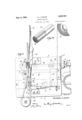
- Fig. 1 is a plan view of the bed of a sewing ⁇ machine embodying the invention.
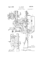
- Fig. 2 is an end elevation of the machine.
- Fig. 3 is a section on the line 3 3, Fig. 2.
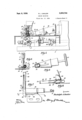
- Fig. 4 is a fragmentary rear side elevation of the machine, showing the puller-feed actuating clutch.
- Fig. 5 is a fragmentary front side elevation of the machine.
- Fig. 6 is a section on the line 6 6
- Fig. 'I is a plan view of the fabric sheath guiding and inverting tube and associated lead-in guide.
- Fig. 8 is a view from ⁇ the left of Fig. 7.
- Fig. 9 is a section on the line 9 9, Fig. 7.
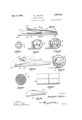
- FIG. 10 is a perspective view of the spiral core-folding guide.
- Fig. 11 is a longitudinal vertical section through the core-'folding guide.
- Figs. 12, 13, 14 and 15 are, respectively, sections on the lines I2-I2, I3-I3, Il--Il and
- Fig. 16 is a perspective view of the inner folding scroll shown in Figs. 10 and 11.
- Fig. 17 is an elevation of a surgical -pad such as produced by aid of the machine of my invention.
- Fig. 18 is a transverse section of the pad shown -in Fig. 17, and
- Fig. 19 is a perspective view of the pad vwith a portion of the sheath broken away to show the core.
- the machine in the preferred embodiment illustrated, preferably comprises a conventional chain-stitch sewing machine having a bed I and gooseneck 2 terminating in the overhanging head I for the reciprocatory needle-bar 4 carrying the eye-pointed needle 5 with which cooperates the usual looper 8 driven bythe main-shaft 1 below the cloth-plate t which is raised above and carried by the bed I.
- the needle reciproeates through the needle- Ii hole 9 in a throat-plate lli having a portion of its upper surface at and in rear of the needle-hole 9 raised somewhat above the level of the clothplate 8, as shown in Fig. 2.
- the usual four-motion feed-dog is preferably l0 omitted, and the presser-foot II, carried by the presser-bar I2, is arranged not to bear upon the raised portion of the throat-plate I0, but to be spaced slightly thereabove, as shown in Fig. 6, so as to function principally to strip the cloth being stitched from the rising needle.
- the narrow gap thus provided between the throat-plate and presser-foot receives the superposed and outwardly protruding edge-portions I3 of a longitudinally folded absorbent fabric-sheath-strip Il and holds them in juxtaposition during the sewing.
- the absorbent fabric-sheath-strip Il is preferably led forwardly over the cloth-plate 8 from the supply reel I5, Fig. 1, to and through a looped wire guide-post I6 and through the wire guideloop Il to the folding guide I8 which is of the conventional English binder type having a U shaped passageway therethrough and provided atits inclined delivery end I9, Fig. 7, with a U shaped inner edge 2li, Fig. 9, around which the longitudinally folded fabric-stripv is inverted and drawn away at an angle of substantially 90 to the direction of travel of the fabric strip before inversion thereof.
- externally and longitudinally of which the folded and inverted fabric-sheath-strip passes from the fabric-strip inverting edge 2li of the folder I8.
- the tube 2l is supported Aonly at its forward end, Fig. 7, as by being soldered to one leg 22 of an angle-bracket the other leg 23 of which may be soldered to the front wall of the folder I8.
- the folder I8 is also preferably provided at its delivery end with the upper and lower edge-confining and guiding iingers 21, Fig. 9, for the sheath-strip as it leaves the folder.
- the core 29 of the present surgical pad is preferably made from multi-ply absorbent; paper stripstock indicated at 28.
- multi-ply absorbent paper strip-stock approximately 2 inches wide and hav'- ing a number of plies sufiiciently to form as nugly lled spongy roll.
- the folder 29 comprises an outer spirally rolled and longitudinally tapered scroll 30 and an inner scroll 3
- the inner edge 32 of the outer scroll fprogresses as a condensing spiral from the large receiving end to the small delivery end of the folder.
- is spacedfrom the outer scroll and prevents-premature collapse'and crumpling of the paper stripas it is being curled sup transversely and progressively into spiral form in its passage through the folder.
- and-the slots 34 in the tube v2 Ij permit the use of a pointed implement or pusher to. assist in threading the beginning ends of thestrips through the respective devices.
- sheathed core 26 runs forwardly in one continuous length to and around the guide pulley 36 and thence rearwardly past the guide-pulley 31 to the ico-actingupper and lower puller-feed rolls 38, 3 9.
- the upper feed-roll 38 is supported by the shaft Y 40 journaled in the bracket 4
- the lower feed-roll 39 is which is journaled in bearing brackets 45 rising from the bed extension v45 screwed tothe bed Step-by-step feeding movements are imparted '-to the shaft 44 by means of a conventional adjustable feed-eccentric 46- on the main-shaft' which is connected by a pitman 41 to the live oscil-A latory clutch-roll spider 48 loose on-the shaft 4 4 and having a clutch-roll carrying portion enterl ing a clutch-cavity 49 inone end of the cylindri-r cal member 5
- fast .to the bearing bushing 52 has an anchor clutch-roll carrying p0rnism of the live and stationary clutchroll spiders z-48, 5I, with the intermediate cylindrical member having clutchroll cavities in its opposite ends, is the conventional pull-feed operating' clutch disclosed, for example, in the patentap- ,plication of Irving Webb; Serial No'. 648,854; papelto form a, spons-y core of substantially um "late or define the length of the stitches made in the sheath I 4' b y ⁇ the stitch-forming mechanism.
- Theus'ual lifting levers 59 and 60 are provided 'for the presser-bars I2 and 42, respectively.
- fabric-sheath guiding and inverting tube,A for presenting an absorbent .coreto said tube, stitch-forming mechanism including a reciprocatory needle arranged tofstitch lsaid sheath in.
- stepby-stepoperating puller-feed mechanism timed in'coperative relation with said needle andarranged to operatively engage aportion of vvthe sheathed core which hasfemerged from said tube.
- a frame including a bed and overhanging bracketarm, a fabric-sheath guiding andinverting tube mounted on said bed, means for directing an absorbent core forwardly and presenting it tothe receiving end of saidtube, stitch-forming mechanism including a reciprocatory. needle arranged to stitch said sheath in tubular formf externally of said tube, amain-shaft connected to drive the stitchforming mechanism, puller-feed mechanism disposed at the rear-of said bracket-e arm and connected'to, be driven by-.said mainshaft, and guiding means mounted forwardly of said tube and around which the sheathed core emerging from said tube runs forwardly and thence rearwardly to said puller-feed mechanism.
- aframe including a bed and overhanging bracket arm, a fabric-sheath guiding and inverting tube mounted on said bed, aspiral strip-folder adapted to spirally curl and snugly but not tightlyf compactacontinuous mutiply strip of absorbent form texture, said strip-folder being disposed in rear of the bracket-arm in position to direct said core forwardly into the receiving end of said tube, stitch-forming mechanism including a reciprocatory needle arranged to stitch said sheath in tubular form externally of said tube, a mainshaft connected to drive the stitch-forming mechanism.
- puller-feed mechanism disposedV at the rear of said bracket-arm alongside said stripfolder, and guiding means mounted forwardly of said tube and around which the sheathed core emerging from said tube runs forwardly and thence rearwardly to said puller-feed mechanism.
- the combination with stitch-forming mechanism including a reciprocatory needle, of a guide-tube disposed transversely of and alongside the path of said needle, means for spirally folding continuous absorbent strip material to form a snugly but not tightly curled spongy core and directing said core into said guide-tube, means for longitudinally folding a covering strip about said guide-tube and presenting the edges oi' said strip to said needle, said guide-tube having a free end about which the stitched covering strip is inverted and drawn into and through said guide-tube in covering relation to said spirally folded core and 'stepby-step operating puller-feed mechanism acting upon said covered core.
- the combination with stitch-forming mechanism including a reciprocatory needle, of a guide-tube disposed transversely of and alongside said needle.
- a fabric-sheath guiding and inverting tube means for longitudinally folding continuous absorbent strip material spirally to form a snugly but -not tightly curled spongy cylindrical core distinct from said sheath and directing said core to said tube, stitch-forming mechanism including a reciprocatory needle arranged to stitch a fabricsheath in tubular form externally of said' tube, and means for feeding the sheathed core through said tube.
Landscapes
- Engineering & Computer Science (AREA)
- Textile Engineering (AREA)
- Sewing Machines And Sewing (AREA)
Description
R. Jl SAU-ER sEwNG MACHINE Sept. 8, 1936.
Filed Jan. 15, 1934 4 SheetS-Sheeb l Sept. 8, 1936.
R. J. SAILER v SEWING MACHINE 4 Sheets-Sheet 2 Filed Jan. l5, 1954 R. J. SAILER SEWING MACHINE Sept. 8, 1936.
Filed Jan. vl5, 1934 4 Sheets-Sheet 3 R. J. SAILE R SEWING MACHNE sept; s, ms;
Filed Jan. 13, 1934 4 Sheets-Sheet 4 Patented Sept.- 8, 1936 UNITED STATES PATENT oFElcE SEWING MACHINE Rudolph J. sauer', rowniey, N. J., mignor u The Singer Manufacturing Company, Elizabeth, N. J., a corporation of New Jersey Application January 13, 1934, Serial No. 706,472
'v claim, l(ci. 11a-z) This invention relates to absorbent surgical pads such, for example, as the small cylindrical saliva-absorbent pads known as dental rolls and commonly used by dentists as oral packing in tooth-filling operations.
The invention has for an object to provide a sewing machine for making an improved absorbent surgical pad of cylindrical contour and uniformly spongy texture throughout, having high absorptive properties and comparatively freeA of hard spots and relatively large voids.
A further object of the invention is to provide a machine for making such pads in one continuous roll from strip-material, to be subsequently cut transversely into individual pads of the desired length.
With the above and other objects in view, as will hereinafter appear, the invention comprises the devices, combinations, and arrangements of parts hereinafter set forth and illustrated Iin the accompanying drawings of a preferred embodiment of the invention, from which the several features ofthe invention and the advantages attained thereby will be readily understood by those skilled in the art.
In the accompanying drawings, Fig. 1 is a plan view of the bed of a sewing` machine embodying the invention. Fig. 2 is an end elevation of the machine. Fig. 3 is a section on the line 3 3, Fig. 2. Fig. 4 is a fragmentary rear side elevation of the machine, showing the puller-feed actuating clutch. Fig. 5 is a fragmentary front side elevation of the machine. Fig. 6 is a section on the line 6 6, Fig. l. Fig. 'I is a plan view of the fabric sheath guiding and inverting tube and associated lead-in guide. Fig. 8 is a view from` the left of Fig. 7. Fig. 9 is a section on the line 9 9, Fig. 7. Fig. 10 is a perspective view of the spiral core-folding guide. Fig. 11 is a longitudinal vertical section through the core-'folding guide. Figs. 12, 13, 14 and 15 are, respectively, sections on the lines I2-I2, I3-I3, Il--Il and |5-I5, Fig. ll. Fig. 16 is a perspective view of the inner folding scroll shown in Figs. 10 and 11. Fig. 17 is an elevation of a surgical -pad such as produced by aid of the machine of my invention. Fig. 18 is a transverse section of the pad shown -in Fig. 17, and Fig. 19 is a perspective view of the pad vwith a portion of the sheath broken away to show the core.
The machine, in the preferred embodiment illustrated, preferably comprises a conventional chain-stitch sewing machine having a bed I and gooseneck 2 terminating in the overhanging head I for the reciprocatory needle-bar 4 carrying the eye-pointed needle 5 with which cooperates the usual looper 8 driven bythe main-shaft 1 below the cloth-plate t which is raised above and carried by the bed I.
The needle reciproeates through the needle- Ii hole 9 in a throat-plate lli having a portion of its upper surface at and in rear of the needle-hole 9 raised somewhat above the level of the clothplate 8, as shown in Fig. 2.
The usual four-motion feed-dog is preferably l0 omitted, and the presser-foot II, carried by the presser-bar I2, is arranged not to bear upon the raised portion of the throat-plate I0, but to be spaced slightly thereabove, as shown in Fig. 6, so as to function principally to strip the cloth being stitched from the rising needle. The narrow gap thus provided between the throat-plate and presser-foot receives the superposed and outwardly protruding edge-portions I3 of a longitudinally folded absorbent fabric-sheath-strip Il and holds them in juxtaposition during the sewing.
The absorbent fabric-sheath-strip Il is preferably led forwardly over the cloth-plate 8 from the supply reel I5, Fig. 1, to and through a looped wire guide-post I6 and through the wire guideloop Il to the folding guide I8 which is of the conventional English binder type having a U shaped passageway therethrough and provided atits inclined delivery end I9, Fig. 7, with a U shaped inner edge 2li, Fig. 9, around which the longitudinally folded fabric-stripv is inverted and drawn away at an angle of substantially 90 to the direction of travel of the fabric strip before inversion thereof.
There is embraced within the delivery end of the folder I8 a fabric-sheath guiding and inverting tube 2| externally and longitudinally of which the folded and inverted fabric-sheath-strip passes from the fabric-strip inverting edge 2li of the folder I8. The tube 2l is supported Aonly at its forward end, Fig. 7, as by being soldered to one leg 22 of an angle-bracket the other leg 23 of which may be soldered to the front wall of the folder I8. Upper and lower transversely curved .leaf-spring members r24, soldered or otherwise secured to the folder I8, bear yieldingly upon the fabric-sheath strip externally of the tube 2i and closely confine the sheath-strip in tubular form while it is being stitched. l I
'I'he stitched tubular sheath passes rearwardly from the stitching point to the free end 25o! the tube 2i where it is inverted or turned inside-out and is drawn together with the core 29 as a continuous roll ftforwardly within the tube 2|, the
raw-edges I3 of the fabric-strip being now concealed within the sheath. The folder I8 is also preferably provided at its delivery end with the upper and lower edge-confining and guiding iingers 21, Fig. 9, for the sheath-strip as it leaves the folder.
The core 29 of the present surgical pad is preferably made from multi-ply absorbent; paper stripstock indicated at 28. For making dental rolls having a' iinished diameter of approximately inch, I prefer to use multi-ply absorbent paper strip-stock approximately 2 inches wide and hav'- ing a number of plies sufiiciently to form as nugly lled spongy roll. I pass this strip-stock through a specially designed spiral-'folder' 29' which longitudinally folds the multi-ply stripf28 and curls it widthwise into a smooth andsnugly filled but not tightly packed spongy cylindrical core 29 and directs such core into the receiving end 25 of the tube 2| around which the fabricsheath is-inverted to envelop the core which is now substantially free of large voids and is of substantially uniformly 'spongytexture throughout. Referring to Figs. 10 to 15, inclusive, the folder 29 comprises an outer spirally rolled and longitudinally tapered scroll 30 and an inner scroll 3| of about half the length ofthe outer scroll supported within the mouth or receiving end of the outer scroll. The inner edge 32 of the outer scroll fprogresses as a condensing spiral from the large receiving end to the small delivery end of the folder. The inner scroll 3| is spacedfrom the outer scroll and prevents-premature collapse'and crumpling of the paper stripas it is being curled sup transversely and progressively into spiral form in its passage through the folder. The slot 33 in the inner scroll 3| and-the slots 34 in the tube v2 Ij permit the use of a pointed implement or pusher to. assist in threading the beginning ends of thestrips through the respective devices.
From the delivery end 35 of thetube 2I,-the
sheathed core 26 runs forwardly in one continuous length to and around the guide pulley 36 and thence rearwardly past the guide-pulley 31 to the ico-actingupper and lower puller-feed rolls 38, 3 9. The upper feed-roll 38 is supported by the shaft Y 40 journaled in the bracket 4| fixed to thelower end of a vertical spring-pressed bar 4 2 slidably mounted 4in the guide-bracket 43 which is screwed to the frame-head 3.
The lower feed-roll 39 is which is journaled in bearing brackets 45 rising from the bed extension v45 screwed tothe bed Step-by-step feeding movements are imparted '-to the shaft 44 by means of a conventional adjustable feed-eccentric 46- on the main-shaft' which is connected by a pitman 41 to the live oscil-A latory clutch-roll spider 48 loose on-the shaft 4 4 and having a clutch-roll carrying portion enterl ing a clutch-cavity 49 inone end of the cylindri-r cal member 5|) fast to the shaft 44. A stationary anchor clutch-roll spider 5| fast .to the bearing bushing 52 has an anchor clutch-roll carrying p0rnism of the live and stationary clutchroll spiders z-48, 5I, with the intermediate cylindrical member having clutchroll cavities in its opposite ends, is the conventional pull-feed operating' clutch disclosed, for example, in the patentap- ,plication of Irving Webb; Serial No'. 648,854; papelto form a, spons-y core of substantially um "late or define the length of the stitches made in the sheath I 4' b y `the stitch-forming mechanism. Theus'ual lifting levers 59 and 60 are provided 'for the presser-bars I2 and 42, respectively.
- It is understood that the continuous roll 26 issuing from the machine is subsequently to be cut inf-the desired lengths to form the surgical pads, such as shownin Fig. 19, The invention is not to be understood as tothe detailsmof construction and relativenrangements of parts of. theupreferred -embodi-i.,
ment of the invention shown and described, as various modifications may obviously be made by those skilled inthe art withinthe spirit. and* scope. of the invention.:
Havingfthus set forth. the nature of the in# 1. In a sewingfmachne, in combination, a.;
fabric-sheath guiding and inverting tube,A for presenting an absorbent .coreto said tube, stitch-forming mechanism including a reciprocatory needle arranged tofstitch lsaid sheath in.
tubular 'forni externally of said tube, andv stepby-stepoperating puller-feed mechanism timed in'coperative relation with said needle andarranged to operatively engage aportion of vvthe sheathed core which hasfemerged from said tube.
2. In a sewing machine, 'incombinatiom a fabricsheath guiding and inverting tube, means for spirally curling a 'continuous multi-ply: strip.. Iof
absorbent materialinto a core and directing-said core into said tube, stitch-forming mechanism.
withsaid needle and arranged tovoperatively; en- Xed t0 the shaft 44 gage a4 portion of the sheathed core which-has emerged from said tube. l
3. In a sewing. machine, in combination, a frame including a bed and overhanging bracketarm, a fabric-sheath guiding andinverting tube mounted on said bed, means for directing an absorbent core forwardly and presenting it tothe receiving end of saidtube, stitch-forming mechanism including a reciprocatory. needle arranged to stitch said sheath in tubular formf externally of said tube, amain-shaft connected to drive the stitchforming mechanism, puller-feed mechanism disposed at the rear-of said bracket-e arm and connected'to, be driven by-.said mainshaft, and guiding means mounted forwardly of said tube and around which the sheathed core emerging from said tube runs forwardly and thence rearwardly to said puller-feed mechanism.
4. Ina sewing machine, in combination, aframe including a bed and overhanging bracket arm, a fabric-sheath guiding and inverting tube mounted on said bed, aspiral strip-folder adapted to spirally curl and snugly but not tightlyf compactacontinuous mutiply strip of absorbent form texture, said strip-folder being disposed in rear of the bracket-arm in position to direct said core forwardly into the receiving end of said tube, stitch-forming mechanism including a reciprocatory needle arranged to stitch said sheath in tubular form externally of said tube, a mainshaft connected to drive the stitch-forming mechanism. puller-feed mechanism disposedV at the rear of said bracket-arm alongside said stripfolder, and guiding means mounted forwardly of said tube and around which the sheathed core emerging from said tube runs forwardly and thence rearwardly to said puller-feed mechanism.
5. In a sewing machine, the combination with stitch-forming mechanism including a reciprocatory needle, of a guide-tube disposed transversely of and alongside the path of said needle, means for spirally folding continuous absorbent strip material to form a snugly but not tightly curled spongy core and directing said core into said guide-tube, means for longitudinally folding a covering strip about said guide-tube and presenting the edges oi' said strip to said needle, said guide-tube having a free end about which the stitched covering strip is inverted and drawn into and through said guide-tube in covering relation to said spirally folded core and 'stepby-step operating puller-feed mechanism acting upon said covered core.
6. In a sewingvmachine, the combination with stitch-forming mechanism including a reciprocatory needle, of a guide-tube disposed transversely of and alongside said needle. means for presenting continuous absorbent strip material in the form of a spongy core to said guide-tube. means for longitudinally folding a covering strip about said guide-tube and presenting the edges of said strip to said needle, said guide-tube having a free end in rear of said needle about which the'stitched covering strip is inverted and drawn forwardly into and through said guide-tube in covering relation to said core, a puller-feed mechanism in rear of said guide-tube, and a pulley in front of said guide-tube around which thecore and its enveloping stitched covering strip run to said puller-feed mechanism.
7. In a sewing machine, in combination, a fabric-sheath guiding and inverting tube, means for longitudinally folding continuous absorbent strip material spirally to form a snugly but -not tightly curled spongy cylindrical core distinct from said sheath and directing said core to said tube, stitch-forming mechanism including a reciprocatory needle arranged to stitch a fabricsheath in tubular form externally of said' tube, and means for feeding the sheathed core through said tube. r RUDOLPH J. SAILER.
Priority Applications (1)
| Application Number | Priority Date | Filing Date | Title |
|---|---|---|---|
| US706472A US2053744A (en) | 1934-01-13 | 1934-01-13 | Sewing machine |
Applications Claiming Priority (1)
| Application Number | Priority Date | Filing Date | Title |
|---|---|---|---|
| US706472A US2053744A (en) | 1934-01-13 | 1934-01-13 | Sewing machine |
Publications (1)
| Publication Number | Publication Date |
|---|---|
| US2053744A true US2053744A (en) | 1936-09-08 |
Family
ID=24837724
Family Applications (1)
| Application Number | Title | Priority Date | Filing Date |
|---|---|---|---|
| US706472A Expired - Lifetime US2053744A (en) | 1934-01-13 | 1934-01-13 | Sewing machine |
Country Status (1)
| Country | Link |
|---|---|
| US (1) | US2053744A (en) |
Cited By (2)
| Publication number | Priority date | Publication date | Assignee | Title |
|---|---|---|---|---|
| US4881358A (en) * | 1983-07-22 | 1989-11-21 | Shampoo Sponge International B.V. | Method of packaging articles of a compressible material |
| US5367965A (en) * | 1992-10-26 | 1994-11-29 | Homemaker Industries, Inc. | Forming a rug from a sewn tubular braid |
-
1934
- 1934-01-13 US US706472A patent/US2053744A/en not_active Expired - Lifetime
Cited By (2)
| Publication number | Priority date | Publication date | Assignee | Title |
|---|---|---|---|---|
| US4881358A (en) * | 1983-07-22 | 1989-11-21 | Shampoo Sponge International B.V. | Method of packaging articles of a compressible material |
| US5367965A (en) * | 1992-10-26 | 1994-11-29 | Homemaker Industries, Inc. | Forming a rug from a sewn tubular braid |
Similar Documents
| Publication | Publication Date | Title |
|---|---|---|
| US2529575A (en) | Sewing machines for making fabric tubes | |
| US1741866A (en) | Combined hem folder and strip guide | |
| US2506325A (en) | Work-guiding attachment for sewing machines | |
| US645236A (en) | Machine for making trimmings. | |
| US1320457A (en) | Blindstitch device for sewing-machines | |
| US1988241A (en) | Seam opening and wind-up device | |
| US2025531A (en) | Method and apparatus for making blind stitched facing | |
| US2282042A (en) | Hemming attachment for sewing machines | |
| US2633816A (en) | Sewing machine | |
| US2376646A (en) | Strip-guiding device for sewing machines | |
| US1816627A (en) | Elastic strip attachment for sewing machines | |
| US2052122A (en) | Sewing machine hemmer | |
| US2334150A (en) | Sewing machine work-guide | |
| US2881725A (en) | Sewing machine attachment | |
| US1557243A (en) | Device for forming round belting | |
| US1746541A (en) | Edge folding and securing means for sewing machines | |
| US2296509A (en) | Sewing machine hemmer | |
| US2096691A (en) | Sewing machine work-guides | |
| US5031551A (en) | Sewing machine attachments | |
| US1624932A (en) | Round fabric belting and its method of manufacture | |
| US1756036A (en) | Sewing machine | |
| US1226461A (en) | Edge-folding and tape-guiding device for sewing-machines. | |
| US1400530A (en) | Strip-folder for sewing-machines | |
| US2113949A (en) | Apparatus and method for making concealed edge trimming | |
| US2818826A (en) | Manufacture of tubular trimming |