US2048901A - Building structure - Google Patents
Building structure Download PDFInfo
- Publication number
- US2048901A US2048901A US702137A US70213733A US2048901A US 2048901 A US2048901 A US 2048901A US 702137 A US702137 A US 702137A US 70213733 A US70213733 A US 70213733A US 2048901 A US2048901 A US 2048901A
- Authority
- US
- United States
- Prior art keywords
- sheets
- walls
- wall
- corrugated
- corrugations
- Prior art date
- Legal status (The legal status is an assumption and is not a legal conclusion. Google has not performed a legal analysis and makes no representation as to the accuracy of the status listed.)
- Expired - Lifetime
Links
- 125000006850 spacer group Chemical group 0.000 description 15
- 239000002184 metal Substances 0.000 description 10
- 229910000831 Steel Inorganic materials 0.000 description 7
- 239000010959 steel Substances 0.000 description 7
- 239000000463 material Substances 0.000 description 6
- 239000000203 mixture Substances 0.000 description 6
- 238000009413 insulation Methods 0.000 description 5
- 238000010276 construction Methods 0.000 description 4
- 238000009408 flooring Methods 0.000 description 4
- 238000009432 framing Methods 0.000 description 4
- 239000004567 concrete Substances 0.000 description 3
- 230000004048 modification Effects 0.000 description 3
- 238000012986 modification Methods 0.000 description 3
- 239000011505 plaster Substances 0.000 description 3
- 241000238631 Hexapoda Species 0.000 description 2
- 239000004568 cement Substances 0.000 description 2
- 239000002131 composite material Substances 0.000 description 2
- 230000000694 effects Effects 0.000 description 2
- 238000005192 partition Methods 0.000 description 2
- 230000035515 penetration Effects 0.000 description 2
- 239000004033 plastic Substances 0.000 description 2
- 229920003023 plastic Polymers 0.000 description 2
- 238000003466 welding Methods 0.000 description 2
- 241000256602 Isoptera Species 0.000 description 1
- 229910001294 Reinforcing steel Inorganic materials 0.000 description 1
- 241000283984 Rodentia Species 0.000 description 1
- 241001591024 Samea Species 0.000 description 1
- 238000005273 aeration Methods 0.000 description 1
- 239000002928 artificial marble Substances 0.000 description 1
- 230000010485 coping Effects 0.000 description 1
- 230000007797 corrosion Effects 0.000 description 1
- 238000005260 corrosion Methods 0.000 description 1
- 238000010891 electric arc Methods 0.000 description 1
- 239000007789 gas Substances 0.000 description 1
- 239000010440 gypsum Substances 0.000 description 1
- 229910052602 gypsum Inorganic materials 0.000 description 1
- 239000011121 hardwood Substances 0.000 description 1
- 238000010438 heat treatment Methods 0.000 description 1
- 239000011810 insulating material Substances 0.000 description 1
- 239000004570 mortar (masonry) Substances 0.000 description 1
- 235000019645 odor Nutrition 0.000 description 1
- 239000003973 paint Substances 0.000 description 1
- 230000000149 penetrating effect Effects 0.000 description 1
- 238000007747 plating Methods 0.000 description 1
- 238000005086 pumping Methods 0.000 description 1
- 230000003014 reinforcing effect Effects 0.000 description 1
- 239000010454 slate Substances 0.000 description 1
- 238000009433 steel framing Methods 0.000 description 1
- 238000006467 substitution reaction Methods 0.000 description 1
- 230000002459 sustained effect Effects 0.000 description 1
- 238000009423 ventilation Methods 0.000 description 1
- 239000002023 wood Substances 0.000 description 1
Images


Classifications
-
- E—FIXED CONSTRUCTIONS
- E04—BUILDING
- E04B—GENERAL BUILDING CONSTRUCTIONS; WALLS, e.g. PARTITIONS; ROOFS; FLOORS; CEILINGS; INSULATION OR OTHER PROTECTION OF BUILDINGS
- E04B1/00—Constructions in general; Structures which are not restricted either to walls, e.g. partitions, or floors or ceilings or roofs
- E04B1/02—Structures consisting primarily of load-supporting, block-shaped, or slab-shaped elements
- E04B1/08—Structures consisting primarily of load-supporting, block-shaped, or slab-shaped elements the elements consisting of metal
-
- E—FIXED CONSTRUCTIONS
- E04—BUILDING
- E04B—GENERAL BUILDING CONSTRUCTIONS; WALLS, e.g. PARTITIONS; ROOFS; FLOORS; CEILINGS; INSULATION OR OTHER PROTECTION OF BUILDINGS
- E04B1/00—Constructions in general; Structures which are not restricted either to walls, e.g. partitions, or floors or ceilings or roofs
- E04B1/38—Connections for building structures in general
- E04B1/41—Connecting devices specially adapted for embedding in concrete or masonry
- E04B1/4178—Masonry wall ties
- E04B1/4185—Masonry wall ties for cavity walls with both wall leaves made of masonry
-
- E—FIXED CONSTRUCTIONS
- E04—BUILDING
- E04B—GENERAL BUILDING CONSTRUCTIONS; WALLS, e.g. PARTITIONS; ROOFS; FLOORS; CEILINGS; INSULATION OR OTHER PROTECTION OF BUILDINGS
- E04B1/00—Constructions in general; Structures which are not restricted either to walls, e.g. partitions, or floors or ceilings or roofs
- E04B1/62—Insulation or other protection; Elements or use of specified material therefor
- E04B1/74—Heat, sound or noise insulation, absorption, or reflection; Other building methods affording favourable thermal or acoustical conditions, e.g. accumulating of heat within walls
- E04B1/76—Heat, sound or noise insulation, absorption, or reflection; Other building methods affording favourable thermal or acoustical conditions, e.g. accumulating of heat within walls specifically with respect to heat only
- E04B1/7608—Heat, sound or noise insulation, absorption, or reflection; Other building methods affording favourable thermal or acoustical conditions, e.g. accumulating of heat within walls specifically with respect to heat only comprising a prefabricated insulating layer, disposed between two other layers or panels
- E04B1/7612—Heat, sound or noise insulation, absorption, or reflection; Other building methods affording favourable thermal or acoustical conditions, e.g. accumulating of heat within walls specifically with respect to heat only comprising a prefabricated insulating layer, disposed between two other layers or panels in combination with an air space
- E04B1/7616—Heat, sound or noise insulation, absorption, or reflection; Other building methods affording favourable thermal or acoustical conditions, e.g. accumulating of heat within walls specifically with respect to heat only comprising a prefabricated insulating layer, disposed between two other layers or panels in combination with an air space with insulation-layer locating devices combined with wall ties
-
- E—FIXED CONSTRUCTIONS
- E04—BUILDING
- E04B—GENERAL BUILDING CONSTRUCTIONS; WALLS, e.g. PARTITIONS; ROOFS; FLOORS; CEILINGS; INSULATION OR OTHER PROTECTION OF BUILDINGS
- E04B2/00—Walls, e.g. partitions, for buildings; Wall construction with regard to insulation; Connections specially adapted to walls
- E04B2/02—Walls, e.g. partitions, for buildings; Wall construction with regard to insulation; Connections specially adapted to walls built-up from layers of building elements
- E04B2/28—Walls having cavities between, but not in, the elements; Walls of elements each consisting of two or more parts kept in distance by means of spacers, all parts being solid
- E04B2/30—Walls having cavities between, but not in, the elements; Walls of elements each consisting of two or more parts kept in distance by means of spacers, all parts being solid using elements having specially designed means for stabilising the position; Spacers for cavity walls
-
- E—FIXED CONSTRUCTIONS
- E04—BUILDING
- E04D—ROOF COVERINGS; SKY-LIGHTS; GUTTERS; ROOF-WORKING TOOLS
- E04D12/00—Non-structural supports for roofing materials, e.g. battens, boards
Definitions
- This invention relates to improvements in building structures and more particularly to composite hollow walls.
- the principal object of the invention is to produce aself framing steel walled building, insulated against heat, cold, sound and moisture, and proof against fire, earthquake, wind, corrosion, insects such as termites, rodents, odors and decay.
- Another object is to conform to the conventional interior and exterior finishes and architectural designs.
- Fig. 1 is a. fragmentary perspective view of a portion of wall constructed in accordance with this invention.
- Fig. 2 is a similar view of the same,-showing the corner construction.
- Fig. 3 is a fragmentary vertical section showing one manner of assembling the interior and exterior insulating finish walls and the corrugated spacing core.
- Fig. 4 is a. detail in perspective of the cross tie clip.
- Fig. 5 is a vertical section of a portion of a building embodying this invention.
- Fig. 6 is a similar view of a portion of the same, illustrating one form of combined floor and celling truss embodying this invention.
- Fig. 7 is a perspective top'view of a roof portion showing the application of conventional roof tiles.
- Fig. 8 is a vertical section of the same, taken on the line VIII-VIII, showing one way of attaching the tile to the roof.
- Fig. 9 is a view similar to a portion of Fig. 5,
- FIG. 10 is an interior view in elevation of the corner of a building, showing a composite double wall structure and the manner of framing doors f and windows within the wall.
- Fig. 11 isan enlarged detail of this wall and foundation in vertical section.
- Fig. 12 isahorizontal section taken at XII-XII, Fig. 10 in fragmentary detail showing one manner of attaching the interior and exterior finishes to the sustainingwall.
- theinvention consists of forming building walls of corrugated steel and applying interior and exterior composition surfaces to the corrugated wall. -j
- the construction illustrated in the drawings comprises the corrugatedsteel core wall I, provided at proper intervals with the holes2. y 5 1
- the cementitious blocks 3, 4 are arranged in superimposed courses on opposite sides of this core wall.
- the tie clips ,5 are extended through the openings 2 and have their angular ends 6-6 embedded in the opposed edges of the blocks 3-4 on opposite sides of the core wall I. See Fig- 3.
- These b1ocks3-4 are preferably composed of aerated cementitious material, such as concrete, gypsum, and similar plastics; The aeration is accomplished by pumping air into the mix, or by introducing reactive materials into the mix that. will generate gases which form bubbles in the blocks while they are in the molds- -Wire mesh lath can beattached to the cor wall and plaster applied in the conventional manner, as shown on the ceiling in Figs. 5 and 6. Plaster board andsimilar. sheets/or insulated metal plates can also be applied in an obvious manner, in lieu of the blocks 3-4. The nature. of the external walls canbe chosen to suit climatic and other controlling conditions.
- the clip shown in Fig. 4 has the body 5, and the angularly bent ends 6-6 adapted to be pushed into the body of the blocks 3-4, the natureof which facilitates the penetration of the cor-' ners 1-1.
- the opposed. curves 8-8 serve the double purpose of forming penetrating points at: 1-1 and as gages for locating these points in the center of the thickness of the blocks 3-4.
- the tapered ends 6-6 serve a similar purpose in sharpening the corners I, the points 9-9 gaging the penetration of the clips to one half their width.
- garages, tool houses, barns; and the like can be made self-framing, substantially as in Fig. 5.
- the attached plating such as the blocks 34, can be omitted.
- a house constructed in accordance with this 5 invention is erected upon any suitable foundation, such as ID in Fig, 5.
- the joists ll rest upon the foundation and have the sill channels l2 leveled thereupon.
- the width of the channels should be equal to the depth of the corruga- 0 tions in the core Wall, which rests'therein, to
- the widths of the sheets form; ing the core wall I may be overlapped to any extent, as at l 2, Fig. 1, to act as reinforcing studding at intervals.
- the sheets of corrugated 'steel l3 are laid transversely on the joists II, as in Fig. 5. These strips to which they are welded at intervals, asat IT. The ends of the sheets l5 are also overlapped and welded.
- the upper corrugations inthe-strips I5 may 0 also be filled with this or other insulating material before the floor boards I8 are laid' on top of the sheets'lS. These boards may be secured to the sheets l5 by drive screws, barbed nails or other available means suitable for the purpose.
- the hardwood flooring l9 or plastic flooring, such asmagnesite, may be laid on the boards l8 in the usual manner. 1
- the room corners may be formed as'in Fig. 2, the edges of the meeting walls 1-! 'being welded" as at 2
- the top plate channels 22,23, are
- corrugated sheets '24 forming .the room ceiling, have their endsor edges laid upon and are welded at 25 to the plate channels- 22, 23.: This completes the welded corrugated cubical which forms the walls, floor and ceiling of the room.' 1%
- the roof is-cornposedof sheets of corrugated are laid transversely of steel 30, 3i, having their upper edges interlocked and joined by the conventional ridge roll 32, to which they are welded. Their lower edges overhang the side walls to form the eaves 33.
- their respective corrugations interlock, either in the structures of Fig. 2 or Fig. 5.
- the corrugations of the ceiling coves 21, and the roof sheets 30, 3! also interlock and may be welded at intervals.
- the truss rods 34, 35 extend from oppositesides of the stringer 29 and extend upwardly to and are bolted to their respective roof sheets 30, 3
- the ceiling sheets 26 act as a chord, or tension brace, to
- the corrugated roof sheets are particularly adaptable to the ornamental use of conventional segmental tiles 36, see Figs. 7, 8. These tiles are suspended by the wires 37, having their upper ends welded to the ridge roll 32. At intervals these wires have loops 38 into which the tie wires 39 are engaged; These tie wires are looped through the usual hole in the upper ends of the tiles and then coiled around the tie wires adjacent the-loops. The lower ends of the wires 31 are fixed to the roof sheets adjacent the eaves 33. In this manner the tiles may be suspended on roofs of any pitch and effectually held against wind, earthquake or other violence of the elements.
- the walls, floors and ceil-' Where it is desiredto install gutters 40 under the eaves, the upper edge of the trough can be flanged to hook over the top of the outer blocks 3 at 4
- the extended edge 42 of the gutter acts as an under trim to give proper finish to the under sides of the eaves.
- the holes 43 through the trough corrugations of the roof sheets discharge rain into the gutters to be disposed of in the usual manner.
- FIG. 6 A modification is shown in Fig. 6 adaptingthis invention to twoormore stories. Corresponding parts are identified by the common designating numerals with an :1: added.
- the ceiling sheets 262 are inclined toward the center to form an arched ceiling with cove corners.
- the fioor sheets I51: and flooring are the sameas previously described.
- the additional elements are thetr'usses 44, 45, 46, preferably formed also of corrugated sheets, so that they will nest into the corrugations of the fioor sheets above and the ceiling sheets below, to which they are welded at proper points of contact.
- This same fioor truss support can be substituted for that'shown in Figs. 5 and 9, where space per-- mits or other conditions make it preferable.
- the various necessary welds indicated are easily accomplished by electric arc welding.
- the metal wall structure can be grounded and an insulated tion is that the sheets fuse together at the spot.
- Metal lath, as on the ceilings, Figs. 5, 6, fixture bases, and. the like, can be attached by welding in this manner.
- the curled ends 41 of the fioor sheets act as supports for the lower course of blocks 4.
- the curved base boards 48 having the curled'lower edges 49, form convenient conduits for electric wiring.
- the corrugated sheets extending in various directions, together with the floor and ceiling structures, provide convenient conduits for wires, pipes, heating and ventilation.
- the surfaces of the blocks 3 and 4 may be painted with cement or oil paints, tints and stucco finishes, as desired.
- Bathroom, kitchen and interior walls may be plated-with artificial marble, metal tile, and like sheets of composition, to attain, in a very simple manner, desirable interior effects.
- corrugated sheets supply all the sustaining and supporting strength and weather protection required.
- the additional elements contribute features of comfort and ornamentation.
- Doors, windows and other openings are installed in accordance with common practice, with proper frames and flashings around openings provided in the walls.
- Additional sustaining strength can be gained by increasing the gage of the sheets and/ or increasing the depth of the corrugations. In'buildings greater than two stories, it is advisable to provide proper reinforcing steel framing and utilize the benefits of this invention in curtain walls and partitions, floors and ceilings, etc.
- the sustaining wall thus far described requires specially formed sheets I with deep corrugations, with their arcs alternating on opposite sides of a common chord line and three or more inches deep, and is intended for an all steel sustaining structure.
- the invention is equally adaptable to the use of the conventional rolled corrugated sheets with shallow sinusoidal corrugations ranging from 11/32 to 1%, inches deep combined with conventional lumber such as 2 x 3 shapes, cOnventional floor joists, rafters, etc., as shown in Figs. 10, 11, 12, wherein the cost may be reduced at the sacrifice of fire, insect and. other protection.
- the conventional steel or wooden joists 50 rest upon the foundation 5
- the fire stop 52 is integral with the concrete floor 53, which is reinforced by the bars 54 and has the nailing strips 55 embedded therein. The floor 53' is nailed to these strips.
- the open channel 56 rests upon the oists 50 and the fire stop 52 to which it may be held by the bolts 51 at intervals.
- the spacer 58 is fixed to the channel to form interspaced grooves within the channel.
- the corrugated vertical sheets 59 and 60 rest within these grooves and are cross nailed or otherwise fixed to the spacer 58 at 6
- a top plate of similar construction comprising the channel 62 and spacer 63 joined by the bolt 64 encloses the top edges of the corrugated sheets 59 and 68 also nailed to the spacer at 65. It is advisable to interpose another spacer 66 intermediate the height of the wall as at 66, in Fig. 10.
- the sill 56, plate 52 and the spacer 66 make three gifts pletely surrounding the building t ture, adding greatly to its lateral and vertical stability.
- the wall is in effect a vertical truss of" great rigidity and light weight.
- the exterior insulation may be composed of vertical panels 61 of suitable composition reinforced as at 6'6 with high rib expanded metal 5 lath or otherwise. These panels of convenient width rest upon the foundation 5
- Fig. 12 shows one manner of attaching the conventional high rib metal lath 18 to the interior of the wall.
- the open ribs H are nailed at intervals to the spacers 63, 66 and 58 within the corrugations of and through the corrugated plate 60. These corrugations permit the wall plaster 12 to extend through and key to the lath Ill.
- the space between corrugated plates 59 and 60 can be filled with any of the many forms of insulating 20 material, if desired.
- Figs. 5 and 10 There are so many types of roofing ranging from high pitch to fiat that only two general types are shown as in Figs. 5 and 10. In the latter, the coping I3 is superposed upon the wall 25 to conceal the roof in the usual manner. In this instance the rafters 14 rest upon the plate 16 in accordance with the general practice in this art.
- sills and plates 15 and 16 may respectively be substituted for the metal 30 channels 56 and 62.
- these sills, plates and spacers 15, 16, 66 provide means for nailing the outer panels 61 to the wall.
- the same T form can be utilized in framing 35 the doors and windows as in Fig. 10, in which the conventional door frame 1'! is inserted within the supporting frame 18, surrounded by the spacers 19 shown in dotted lines.
- the corrugated plates 59 and 68 are nailed to the spacers 19- as previously described in relation to the sills and plates.
- Fig. 1 For partitions, closet walls, etc., the structure in Fig. 1 with reduced cross-section can be introduced, utilizing thin panels such as 61 instead of the blocks 3 and 4.
- a modification of the baseboard conduit 49 in Fig. 5 is shown in Fig. 11 and comprises the bent plate embedded in the floor 53 and having the extended upper edge 8
- the base board is a bent plate 82 having the bottom flange 83 interposed between the floor 53 and the plate 80. Its upper edge hooks over this plate at 84.
- the base plate 82 may be removed by introducing a pry through the slot at 85.
- corrugated steel sheets have been used as sheathing plates for buildings. But to the best of my knowledge, it is novel to utilize corrugated sheets as sustaining walls and as spacing cores in the hollow walls of buildings.
- a building structure including horizontallyinterspaced vertically corrugated sheets; and joining members having spacers extending between and lateral flanges enclosing the ends of said sheets. 7 v i I 5.
- a building structure including horizontally interspaced sustaining walls; spacers between said walls; and an enclosing wall attached to said spacers.
- a building structure including horizontally interspaced sustaining walls; joining members extending between and overhanging the ends of said walls; and interlocking wall, panels attached to said joining members.
- a building structure including a vertically.
- corrugated wall metal lath having ribs extending into said corrugations and fixed to said wall.
- a building structure including a plurality of horizontally interspaced vertically corrugated sheets; joining members extendingbetween said sheets; and a metal lath having ribs extending into said corrugations and attached to said joining members.
- a wall in the class described including a vertical sustaining sheet having undulating vertical corrugations; and conventional metal lath superimposed upon said sheets.
- a building structure in the class described including horizontally interspaced vertically corrugated sustaining sheets; spacers between and supported by said sheets; and a wall overlying said sheets.
Landscapes
- Engineering & Computer Science (AREA)
- Architecture (AREA)
- Physics & Mathematics (AREA)
- Civil Engineering (AREA)
- Structural Engineering (AREA)
- Electromagnetism (AREA)
- Acoustics & Sound (AREA)
- Building Environments (AREA)
Description
July 28, 1936. B.,VALE
BUILDING STRUCTURE Filed Dec. 15, 1953 5 Sheets-Sheet 1 INVENTOR July 28, 1936. B, VALE 2,048,901
- BUILDING STRUCTURE Filed Dec. 15, 1933 5 Sheets-Sheet 2 INVENTOR July 28, 1936. VALE 2,048,901
BUILDING STRUCTURE Filed Dec. 13, 1955 5 Sheets-Sheet 5 IN VENTOR.
B. VALE July 28, 1936.
BUILDING S TRUCTURE 1955 5 Sheets-Sheet Filed Dec. 13
INVENTOR:
July 28, 1936.
B. VALE BUILD ING STRUCTURE Filed Dec. 13, 1933 5 Sheets-Sheet 5 e2 FIGJI.
FIG. l2.
Wwam
INVENTOR Patented July 28, 1936 UNETED STATES PATENT oFF cE N 2.04am
2,048,901 BUILDING STRUCTURE Baldwin Vale, San Francisco, Calif.
Application December 13, 1933, Serial No. 702,137
10 Claims.
This invention relates to improvements in building structures and more particularly to composite hollow walls.
The principal object of the invention is to produce aself framing steel walled building, insulated against heat, cold, sound and moisture, and proof against fire, earthquake, wind, corrosion, insects such as termites, rodents, odors and decay.
Another object is to conform to the conventional interior and exterior finishes and architectural designs.
Further objects are to'reduce the cost of material and labor items and simplify the construction of the types of buildings to which the invention is applicable.
Other objects and advantages will appear as the description progresses.
In this specification and the accompanyingdrawings the invention is disclosed in its preferred form. It is to be understood, however,
that it is not limited to this form because it may be embodied in other forms without departing from the spirit of the invention as defined in the claims following the description.
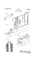
In the five sheets of drawings:
Fig. 1 is a. fragmentary perspective view of a portion of wall constructed in accordance with this invention.
Fig. 2 is a similar view of the same,-showing the corner construction.
Fig. 3 is a fragmentary vertical section showing one manner of assembling the interior and exterior insulating finish walls and the corrugated spacing core.
Fig. 4 is a. detail in perspective of the cross tie clip.
Fig. 5 is a vertical section of a portion of a building embodying this invention.
Fig. 6 is a similar view of a portion of the same, illustrating one form of combined floor and celling truss embodying this invention.
Fig. 7 is a perspective top'view of a roof portion showing the application of conventional roof tiles.
Fig. 8 is a vertical section of the same, taken on the line VIII-VIII, showing one way of attaching the tile to the roof.
Fig. 9 is a view similar to a portion of Fig. 5,
showing in detail a modified form of floor joist structure.
- Fig. 10 is an interior view in elevation of the corner of a building, showing a composite double wall structure and the manner of framing doors f and windows within the wall. I
Fig. 11 isan enlarged detail of this wall and foundation in vertical section.
Fig. 12 isahorizontal section taken at XII-XII, Fig. 10 in fragmentary detail showing one manner of attaching the interior and exterior finishes to the sustainingwall.
Broadly stated, theinvention consists of forming building walls of corrugated steel and applying interior and exterior composition surfaces to the corrugated wall. -j
In detail the construction illustrated in the drawings, comprises the corrugatedsteel core wall I, provided at proper intervals with the holes2. y 5 1 The cementitious blocks 3, 4 are arranged in superimposed courses on opposite sides of this core wall. The tie clips ,5 are extended through the openings 2 and have their angular ends 6-6 embedded in the opposed edges of the blocks 3-4 on opposite sides of the core wall I. See Fig- 3.
These b1ocks3-4 are preferably composed of aerated cementitious material, such as concrete, gypsum, and similar plastics; The aeration is accomplished by pumping air into the mix, or by introducing reactive materials into the mix that. will generate gases which form bubbles in the blocks while they are in the molds- -Wire mesh lath can beattached to the cor wall and plaster applied in the conventional manner, as shown on the ceiling in Figs. 5 and 6. Plaster board andsimilar. sheets/or insulated metal plates can also be applied in an obvious manner, in lieu of the blocks 3-4. The nature. of the external walls canbe chosen to suit climatic and other controlling conditions.
It is advantageous topreserve the air space provided between the external walls by the curvilineal corrugations ofthecore wall I. This air space. contributes to the thermal insulation of the wall as a whole.
The clip shown in Fig. 4 has the body 5, and the angularly bent ends 6-6 adapted to be pushed into the body of the blocks 3-4, the natureof which facilitates the penetration of the cor-' ners 1-1. The opposed. curves 8-8 serve the double purpose of forming penetrating points at: 1-1 and as gages for locating these points in the center of the thickness of the blocks 3-4. The tapered ends 6-6 serve a similar purpose in sharpening the corners I, the points 9-9 gaging the penetration of the clips to one half their width. These clips can be varied in accordance with the nature of the attached material.
It is obvious that garages, tool houses, barns; and the like, can be made self-framing, substantially as in Fig. 5. In such instances the attached plating, such as the blocks 34, can be omitted.
A house constructed in accordance with this 5 invention is erected upon any suitable foundation, such as ID in Fig, 5. The joists ll rest upon the foundation and have the sill channels l2 leveled thereupon. The width of the channels should be equal to the depth of the corruga- 0 tions in the core Wall, which rests'therein, to
, are overlapped longitudinally and welded to stabilize the corrugations of the core walls which sustain the Weight of the superstructure.
Where additional sustaining strength or lateral stability is desired, the widths of the sheets form; ing the core wall I may be overlapped to any extent, as at l 2, Fig. 1, to act as reinforcing studding at intervals. v
The sheets of corrugated 'steel l3 are laid transversely on the joists II, as in Fig. 5. These strips to which they are welded at intervals, asat IT. The ends of the sheets l5 are also overlapped and welded. The corrugations of the sheets I 3-l5 superimposed transversely on top of the joists ll, make a veryrigid floor foundation. It is desirable to interpose aerated concrete between the sheets l3l5, which expands, as described, and will fill the corrugations running in transverse directions. This adds to the rigidity of the fioor and affords thermal insulation.
' The upper corrugations inthe-strips I5 may 0 also be filled with this or other insulating material before the floor boards I8 are laid' on top of the sheets'lS. These boards may be secured to the sheets l5 by drive screws, barbed nails or other available means suitable for the purpose. The hardwood flooring l9 or plastic flooring, such asmagnesite, may be laid on the boards l8 in the usual manner. 1
Where firerestrictions will permitfthe usual wooden joists and flooring can be substituted forthe assembly'll to l9.' In such substitutions the walls la: can be nailed at 20 to the 'ends' or sides of the adjacent joists lllr, see 'dottedi'nails, as
in Fig. 9.
The room corners may be formed as'in Fig. 2, the edges of the meeting walls 1-! 'being welded" as at 2|. The top plate channels 22,23, are
mitered and welded at the corners','to*form a rectangular girt around the room in vertical alinement with the sills l2. This gives additionalstability to the structure. J
The corrugated sheets '24," forming .the room ceiling, have their endsor edges laid upon and are welded at 25 to the plate channels- 22, 23.: This completes the welded corrugated cubical which forms the walls, floor and ceiling of the room.' 1%
If cove corners are desired, as in" Fig. 5,'th ceiling sheets 26 have their ends'or sides curved transversely to their planes, as at 21, to meet and be welded to'the walls I. In this structure the plate channels; 22, 23 are not required. J The inner ends ofthese sheets'overlap and are welded together and bolted'at 28 to the stringer 'channel 29.
The roof is-cornposedof sheets of corrugated are laid transversely of steel 30, 3i, having their upper edges interlocked and joined by the conventional ridge roll 32, to which they are welded. Their lower edges overhang the side walls to form the eaves 33. Where the roof sheets meet the core walls I, their respective corrugations interlock, either in the structures of Fig. 2 or Fig. 5. The corrugations of the ceiling coves 21, and the roof sheets 30, 3! also interlock and may be welded at intervals. The truss rods 34, 35 extend from oppositesides of the stringer 29 and extend upwardly to and are bolted to their respective roof sheets 30, 3| to support the ceiling. The ceiling sheets 26 act as a chord, or tension brace, to
'form a truss with the inclined roof sheets 30, 3 I. The corrugated roof sheets are particularly adaptable to the ornamental use of conventional segmental tiles 36, see Figs. 7, 8. These tiles are suspended by the wires 37, having their upper ends welded to the ridge roll 32. At intervals these wires have loops 38 into which the tie wires 39 are engaged; These tie wires are looped through the usual hole in the upper ends of the tiles and then coiled around the tie wires adjacent the-loops. The lower ends of the wires 31 are fixed to the roof sheets adjacent the eaves 33. In this manner the tiles may be suspended on roofs of any pitch and effectually held against wind, earthquake or other violence of the elements.
' It-is obvious that horizontal wooden sheathing strips may be fixed to the roofing sheets 30, 3|, to which shingles, slate or'other forms of roofing can be attached for ornament or increased thermal insulation. It is also desirable to flow aerated cement on top of the ceiling plates 26 to improve thermal insulation. 7
It is to be noted that the walls, floors and ceil-' Where it is desiredto install gutters 40 under the eaves, the upper edge of the trough can be flanged to hook over the top of the outer blocks 3 at 4|. The extended edge 42 of the gutter acts as an under trim to give proper finish to the under sides of the eaves. The holes 43 through the trough corrugations of the roof sheets discharge rain into the gutters to be disposed of in the usual manner.
A modification is shown in Fig. 6 adaptingthis invention to twoormore stories. Corresponding parts are identified by the common designating numerals with an :1: added. In the suggestive modification the ceiling sheets 262: are inclined toward the center to form an arched ceiling with cove corners.
The fioor sheets I51: and flooring are the sameas previously described. The additional elements are thetr'usses 44, 45, 46, preferably formed also of corrugated sheets, so that they will nest into the corrugations of the fioor sheets above and the ceiling sheets below, to which they are welded at proper points of contact. This same fioor truss support can be substituted for that'shown in Figs. 5 and 9, where space per-- mits or other conditions make it preferable.
The various necessary welds indicated are easily accomplished by electric arc welding. The metal wall structure can be grounded and an insulated tion is that the sheets fuse together at the spot. Metal lath, as on the ceilings, Figs. 5, 6, fixture bases, and. the like, can be attached by welding in this manner.
The curled ends 41 of the fioor sheets, act as supports for the lower course of blocks 4. The curved base boards 48, having the curled'lower edges 49, form convenient conduits for electric wiring. The corrugated sheets extending in various directions, together with the floor and ceiling structures, provide convenient conduits for wires, pipes, heating and ventilation.
The surfaces of the blocks 3 and 4 may be painted with cement or oil paints, tints and stucco finishes, as desired. Bathroom, kitchen and interior walls may be plated-with artificial marble, metal tile, and like sheets of composition, to attain, in a very simple manner, desirable interior effects.
One of the primary advantages of this inventhe corrugated sheets supply all the sustaining and supporting strength and weather protection required. The additional elements contribute features of comfort and ornamentation.
Doors, windows and other openings are installed in accordance with common practice, with proper frames and flashings around openings provided in the walls.
Additional sustaining strength can be gained by increasing the gage of the sheets and/ or increasing the depth of the corrugations. In'buildings greater than two stories, it is advisable to provide proper reinforcing steel framing and utilize the benefits of this invention in curtain walls and partitions, floors and ceilings, etc.
The sustaining wall thus far described requires specially formed sheets I with deep corrugations, with their arcs alternating on opposite sides of a common chord line and three or more inches deep, and is intended for an all steel sustaining structure. The invention is equally adaptable to the use of the conventional rolled corrugated sheets with shallow sinusoidal corrugations ranging from 11/32 to 1%, inches deep combined with conventional lumber such as 2 x 3 shapes, cOnventional floor joists, rafters, etc., as shown in Figs. 10, 11, 12, wherein the cost may be reduced at the sacrifice of fire, insect and. other protection.
In Fig. 10, the conventional steel or wooden joists 50 rest upon the foundation 5| and are joined by the usual fire stop. In Fig. 11 the fire stop 52 is integral with the concrete floor 53, which is reinforced by the bars 54 and has the nailing strips 55 embedded therein. The floor 53' is nailed to these strips.
The open channel 56 rests upon the oists 50 and the fire stop 52 to which it may be held by the bolts 51 at intervals. The spacer 58 is fixed to the channel to form interspaced grooves within the channel. The corrugated vertical sheets 59 and 60 rest within these grooves and are cross nailed or otherwise fixed to the spacer 58 at 6| depending upon the composition of the spacer, thus forming the sill of the wall.
A top plate of similar construction comprising the channel 62 and spacer 63 joined by the bolt 64 encloses the top edges of the corrugated sheets 59 and 68 also nailed to the spacer at 65. It is advisable to interpose another spacer 66 intermediate the height of the wall as at 66, in Fig. 10. The sill 56, plate 52 and the spacer 66 make three gifts pletely surrounding the building t ture, adding greatly to its lateral and vertical stability. The wall is in effect a vertical truss of" great rigidity and light weight.
In Fig. 11 the exterior insulation may be composed of vertical panels 61 of suitable composition reinforced as at 6'6 with high rib expanded metal 5 lath or otherwise. These panels of convenient width rest upon the foundation 5|, are embedded in mortar and are held at their tops between the angular plate 69 and the adjacent channel plate 62. Their edges overlap with a sealed joint as at 69 in Fig. 12.
Fig. 12 shows one manner of attaching the conventional high rib metal lath 18 to the interior of the wall. The open ribs H are nailed at intervals to the spacers 63, 66 and 58 within the corrugations of and through the corrugated plate 60. These corrugations permit the wall plaster 12 to extend through and key to the lath Ill. The space between corrugated plates 59 and 60 can be filled with any of the many forms of insulating 20 material, if desired.
There are so many types of roofing ranging from high pitch to fiat that only two general types are shown as in Figs. 5 and 10. In the latter, the coping I3 is superposed upon the wall 25 to conceal the roof in the usual manner. In this instance the rafters 14 rest upon the plate 16 in accordance with the general practice in this art.
As in Fig. 10, wooden sills and plates 15 and 16 may respectively be substituted for the metal 30 channels 56 and 62. In the less expensive structures where wood is acceptable, these sills, plates and spacers 15, 16, 66 provide means for nailing the outer panels 61 to the wall.
The same T form can be utilized in framing 35 the doors and windows as in Fig. 10, in which the conventional door frame 1'! is inserted within the supporting frame 18, surrounded by the spacers 19 shown in dotted lines. The corrugated plates 59 and 68 are nailed to the spacers 19- as previously described in relation to the sills and plates.
For partitions, closet walls, etc., the structure in Fig. 1 with reduced cross-section can be introduced, utilizing thin panels such as 61 instead of the blocks 3 and 4.
A modification of the baseboard conduit 49 in Fig. 5 is shown in Fig. 11 and comprises the bent plate embedded in the floor 53 and having the extended upper edge 8|. The base board is a bent plate 82 having the bottom flange 83 interposed between the floor 53 and the plate 80. Its upper edge hooks over this plate at 84. The base plate 82 may be removed by introducing a pry through the slot at 85.
I am aware that corrugated steel sheets have been used as sheathing plates for buildings. But to the best of my knowledge, it is novel to utilize corrugated sheets as sustaining walls and as spacing cores in the hollow walls of buildings.
Having thus described this invention, what is 60 claimed and desired to secure by Letters Patent walls and ceiling composed of curvilineally'corrugated sheet material, the edges of said ceiling sheets being coved transversely to their planes and interlocked with the corrugations of said walls; and inclined corrugated roofsheets joined at their apexes and to said coves and sustained by said walls.
4. A building structure including horizontallyinterspaced vertically corrugated sheets; and joining members having spacers extending between and lateral flanges enclosing the ends of said sheets. 7 v i I 5. A building structure including horizontally interspaced sustaining walls; spacers between said walls; and an enclosing wall attached to said spacers.
6. A building structure including horizontally interspaced sustaining walls; joining members extending between and overhanging the ends of said walls; and interlocking wall, panels attached to said joining members.
7. A building structure including a vertically.
corrugated wall; metal lath having ribs extending into said corrugations and fixed to said wall.
8. A building structure including a plurality of horizontally interspaced vertically corrugated sheets; joining members extendingbetween said sheets; and a metal lath having ribs extending into said corrugations and attached to said joining members.
9. A wall in the class described including a vertical sustaining sheet having undulating vertical corrugations; and conventional metal lath superimposed upon said sheets.
10. A building structure in the class described including horizontally interspaced vertically corrugated sustaining sheets; spacers between and supported by said sheets; and a wall overlying said sheets.
BALDWIN VALE.
Priority Applications (1)
| Application Number | Priority Date | Filing Date | Title |
|---|---|---|---|
| US702137A US2048901A (en) | 1933-12-13 | 1933-12-13 | Building structure |
Applications Claiming Priority (1)
| Application Number | Priority Date | Filing Date | Title |
|---|---|---|---|
| US702137A US2048901A (en) | 1933-12-13 | 1933-12-13 | Building structure |
Publications (1)
| Publication Number | Publication Date |
|---|---|
| US2048901A true US2048901A (en) | 1936-07-28 |
Family
ID=24819993
Family Applications (1)
| Application Number | Title | Priority Date | Filing Date |
|---|---|---|---|
| US702137A Expired - Lifetime US2048901A (en) | 1933-12-13 | 1933-12-13 | Building structure |
Country Status (1)
| Country | Link |
|---|---|
| US (1) | US2048901A (en) |
Cited By (5)
| Publication number | Priority date | Publication date | Assignee | Title |
|---|---|---|---|---|
| US2576530A (en) * | 1947-01-08 | 1951-11-27 | Leon E Medal | Panel construction |
| US2642017A (en) * | 1950-08-04 | 1953-06-16 | Cooper | Roof drainage system for toll booth canopies |
| US4180956A (en) * | 1977-04-06 | 1980-01-01 | Fernand Gross | Wall tie and a wall incorporating the wall tie |
| US20050188712A1 (en) * | 2004-02-20 | 2005-09-01 | Noise Solutions Inc. | Integrated noise and heat management system |
| US20090301019A1 (en) * | 2006-04-24 | 2009-12-10 | Bc & I Enviro Solutions Pty Ltd | Building system, building element and methods of construction |
-
1933
- 1933-12-13 US US702137A patent/US2048901A/en not_active Expired - Lifetime
Cited By (7)
| Publication number | Priority date | Publication date | Assignee | Title |
|---|---|---|---|---|
| US2576530A (en) * | 1947-01-08 | 1951-11-27 | Leon E Medal | Panel construction |
| US2642017A (en) * | 1950-08-04 | 1953-06-16 | Cooper | Roof drainage system for toll booth canopies |
| US4180956A (en) * | 1977-04-06 | 1980-01-01 | Fernand Gross | Wall tie and a wall incorporating the wall tie |
| US20050188712A1 (en) * | 2004-02-20 | 2005-09-01 | Noise Solutions Inc. | Integrated noise and heat management system |
| US7201011B2 (en) * | 2004-02-20 | 2007-04-10 | Noise Solutions Inc. | Integrated noise and heat management system |
| US20090301019A1 (en) * | 2006-04-24 | 2009-12-10 | Bc & I Enviro Solutions Pty Ltd | Building system, building element and methods of construction |
| US7895796B2 (en) * | 2006-04-24 | 2011-03-01 | BC&I ENVIRO SOLUTIONS Pty. Ltd. | Building system, building element and methods of construction |
Similar Documents
| Publication | Publication Date | Title |
|---|---|---|
| US4052829A (en) | Semi-prefabricated monolithic steel-reinforced cement building construction | |
| US20080196349A1 (en) | Connected structural panels for buildings | |
| US1858701A (en) | Building construction | |
| GB2132245A (en) | Pre-fabricated building construction | |
| US3678638A (en) | Building construction of modular units with settable material therebetween | |
| US3744197A (en) | Building structure | |
| US2202783A (en) | Wall structure | |
| KR20010012388A (en) | Modular Sandwich Panel and Method for Housing Construction | |
| US3149437A (en) | Building construction | |
| US2348180A (en) | Building structure | |
| US2048901A (en) | Building structure | |
| US2372768A (en) | Building construction | |
| US1955818A (en) | Metallic frame for buildings | |
| US3466818A (en) | Prefabricated buildings | |
| US1910264A (en) | Building construction | |
| US2181169A (en) | Prefabricated house | |
| US6145263A (en) | Light gauge sheet metal building construction system | |
| US1988253A (en) | Metallic structure | |
| WO2000047836A1 (en) | Wall construction system | |
| US3609936A (en) | Method for constructing low cost housing units | |
| US2212906A (en) | Building construction | |
| KR200425116Y1 (en) | Prefab container classroom | |
| JPS60215957A (en) | Wall panel for prefabricated structure and prefabricated structure containing said wall panel | |
| GB2200383A (en) | Engineered housing | |
| AU2009279384A1 (en) | Modular building construction system |