US202808A - Improvement in manufacture of heels for boots and shoes - Google Patents
Improvement in manufacture of heels for boots and shoes Download PDFInfo
- Publication number
- US202808A US202808A US202808DA US202808A US 202808 A US202808 A US 202808A US 202808D A US202808D A US 202808DA US 202808 A US202808 A US 202808A
- Authority
- US
- United States
- Prior art keywords
- blank
- arms
- leather
- boots
- manufacture
- Prior art date
- Legal status (The legal status is an assumption and is not a legal conclusion. Google has not performed a legal analysis and makes no representation as to the accuracy of the status listed.)
- Expired - Lifetime
Links
- 238000004519 manufacturing process Methods 0.000 title description 5
- 239000010985 leather Substances 0.000 description 13
- 230000037303 wrinkles Effects 0.000 description 3
- 238000010586 diagram Methods 0.000 description 2
- 238000000034 method Methods 0.000 description 2
- 101100310856 Drosophila melanogaster spri gene Proteins 0.000 description 1
- 239000004568 cement Substances 0.000 description 1
- 230000000052 comparative effect Effects 0.000 description 1
- 230000000694 effects Effects 0.000 description 1
- 238000003825 pressing Methods 0.000 description 1
Images
Classifications
-
- A—HUMAN NECESSITIES
- A43—FOOTWEAR
- A43D—MACHINES, TOOLS, EQUIPMENT OR METHODS FOR MANUFACTURING OR REPAIRING FOOTWEAR
- A43D25/00—Devices for gluing shoe parts
- A43D25/12—Devices for gluing heel-breasts to heels or for gluing coverings on heels
- A43D25/126—Devices for glueing coverings on heels
Definitions
- My invention relates to the manufacture of that class of boot and shoe heelswhich consist of wooden blanks covered with leather, these covered blanks being extensively used iii-making boots for ladies; and the object of my invention is to rapidly cover the edges of the blanks with leather in such a manner that the latter shall be smooth and even and free from creases and wrinkles.
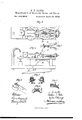
- Figures 1 and 2 are diagrams illustrating the mode of carrying my invention into effect;
- Fig. 3 a plan view of the machine which I prefer to use in applying the leather to the heel-blank;
- Fig. 4 a side View of the machine;
- Fig. 5, a plan view, representing part of the machine;
- Fig. 6, an end View of the jaws for applying the leather;
- Fig. 7, a transverse section, drawn to an enlarged scale, on the line 1 2, Fig. 3.
- the inside of the strip of leather or the edge of the blank, or both is first coated with suitable paste or cement, and the strip then applied to the curved edge of the heelblank and pressed to the same by hand.
- the leather after being thus applied, is uneven, and does not fit snugly to the curves of the blank. Hence it is usually rubbed down with suitable instruments until comparative smoothness and adhesion at all points are attained.
- the elastic strip is wide enough to overlap the blank at m and underlap it at n, Fig. 2, so that it will serve to turn the edges of theleather and cause them to adhere to the top and bottom of the blank.
- a pin, '0 which projects into a curved slot formed in the top of the curved arm K, the two arms, which are connected together at their outer ends by a spring, y, being arranged in respect to each other in the manner shown, and being pivoted to pins q q on the guides F.
- each spring-arm carrying at its outer end a pin or roller for bearing laterally against a rib, t, on the under side of one of the slotted arms.
- An enlargement, p is formed at the end of the short arm t of each of the levers I I, the enlargement being made to conform approximately to the edges of the heel-blank, which is placed on the rest W.
- One end of the clastic strip D is secured to the enlargement of the arm 6 of one lever I, and the other end to the enlargement of the arm of the other lever.
- a heel-blank with its leather covering, which has been applied by hand, is placed on the rest W, and held thereon by the hooked end of a vertical bar, Y, which is arranged to slide in the base 0, and which can be either held by the operators hand or may be combined with mechanism which places it under the control of his foot.
- the cross-head By operating the segment G, the cross-head, with its levers, is moved in the direction of the arrow, as are also the spring-arms M M, which, bearing against the inner side of the ribs t t on the under side of the slotted arms K K, move the latter on their pivots outward from each other, and as the levers are controlled by the slots in the said arms, the enlargements p p of the short arms of the levers Will embrace the heel-blank and insure the proper application of the elastic strip to the same.
- the method herein described of applying a leather cover to heel-blanks by first cementing the leather to the blank, and then applying an elastic strip, while in a stretched condition, to the edge and under and over the blank, as set forth.
Landscapes
- Treatment And Processing Of Natural Fur Or Leather (AREA)
Description
S. T. GATES.
Manufacture of Heels for Boots and Shoes.
Patented April 23,1878.
".PEI'ERS, FHDTWLITHOGRAPHER. WASX-IING'WJNv D C.
' UNITE STATES PATENT OFFICE.
'SELDONT. GATES, OF PHILADELPHIA, PENNSYLVANIA, ASSIGNOR TO EDWARD P. KNIPE, OF SAME PLACE.
IMPROVEMENT IN MANUFACTURE OF HEELS FOR BOOTS AND SHOES.
Specification forming part of Letters Patent No. 202,808, dated April 23, 1878; application filed October 16, 1877.
To all whom it may concern:
Be it known that I, SELDoN'T. GATES, of Philadelphia, Pennsylvania, have invented a new and -useful Improvement in the Manufacture of Heels for Boots and Shoes, and in machinery therefor, of which the following is a specification:
My invention relates to the manufacture of that class of boot and shoe heelswhich consist of wooden blanks covered with leather, these covered blanks being extensively used iii-making boots for ladies; and the object of my invention is to rapidly cover the edges of the blanks with leather in such a manner that the latter shall be smooth and even and free from creases and wrinkles.
In the accompanying drawing, Figures 1 and 2 are diagrams illustrating the mode of carrying my invention into effect; Fig. 3, a plan view of the machine which I prefer to use in applying the leather to the heel-blank; Fig. 4, a side View of the machine; Fig. 5, a plan view, representing part of the machine; Fig. 6, an end View of the jaws for applying the leather; and Fig. 7, a transverse section, drawn to an enlarged scale, on the line 1 2, Fig. 3.
The mode of carrying out my invention may be best explained byrefercnce to the diagrams, Figs. 1 and 2, in which A represents a wooden heel-blank, to be clothed at the edge with kid or other leather, B.
Ordinarily the inside of the strip of leather or the edge of the blank, or both, is first coated with suitable paste or cement, and the strip then applied to the curved edge of the heelblank and pressed to the same by hand. The leather, after being thus applied, is uneven, and does not fit snugly to the curves of the blank. Hence it is usually rubbed down with suitable instruments until comparative smoothness and adhesion at all points are attained.
I discard this tedious and unsatisfactory process, and use an elastic strip, D, of rubber, one end of which is held to one side of the leather-covered blank at as, while the strip is stretched and Wrapped, while in a stretched condition, around theedge of the blank against the leather. As the elastic strip has a tendency to conform to the curved edge of the blank, it must necessarily be the medium of applying pressure to all parts of the leather, which will consequent-1y be smoothly and evenly cemented to the blank, and will be free from wrinkles and creases.
It should be understood that the elastic strip is wide enough to overlap the blank at m and underlap it at n, Fig. 2, so that it will serve to turn the edges of theleather and cause them to adhere to the top and bottom of the blank.
While the above operations may be accomplished by hand, they may be much more readily conducted by the aid of the machine which I will now proceed to describe.
Toa suitable base, 0, are secured guides E E for a cross-head, F, which can be moved to and fro on the said guides, in the present instance by a toothed segment, G, pivoted to the base, and provided with an operating-arm, G. To this cross-head are pivoted, by means of pins w w, the two levers I I, the short arms it of which form jaws for applying the rubber strip to the heel-blank, in the manner described hereinafter.
At the end of the long arm j of each lever, on the under side of the same, is secured a pin, '0, which projects into a curved slot formed in the top of the curved arm K, the two arms, which are connected together at their outer ends by a spring, y, being arranged in respect to each other in the manner shown, and being pivoted to pins q q on the guides F.
To the rear of the cross-head F are secured two spring-arms, M M, arranged beneath the slotted arms K K, each spring-arm carrying at its outer end a pin or roller for bearing laterally against a rib, t, on the under side of one of the slotted arms.
An enlargement, p, is formed at the end of the short arm t of each of the levers I I, the enlargement being made to conform approximately to the edges of the heel-blank, which is placed on the rest W. One end of the clastic strip D is secured to the enlargement of the arm 6 of one lever I, and the other end to the enlargement of the arm of the other lever.
The cross-head, with its two levers I I and spring arms M M, being in the position shown in Figs. 3, 4, and 5, a heel-blank, with its leather covering, which has been applied by hand, is placed on the rest W, and held thereon by the hooked end of a vertical bar, Y, which is arranged to slide in the base 0, and which can be either held by the operators hand or may be combined with mechanism which places it under the control of his foot.
By operating the segment G, the cross-head, with its levers, is moved in the direction of the arrow, as are also the spring-arms M M, which, bearing against the inner side of the ribs t t on the under side of the slotted arms K K, move the latter on their pivots outward from each other, and as the levers are controlled by the slots in the said arms, the enlargements p p of the short arms of the levers Will embrace the heel-blank and insure the proper application of the elastic strip to the same.
It will be seen that the pressure of the short arms of the levers is a yielding pressure, owing to the spring-arms M M. When the crosshead has reached the limit of its forward movement the ends of the spring-arms are clear of the ribs t t, and the rollers or pins move apart.
After the leather covering has been tightly pressed against the wooden heel-blank by the above operations the cross-head and levers must be moved back to their original positions, in doing which the rollers or pins on the ends of the spri'n g-arms will traverse in contact with the outer edges of the ribs t t of the slotted arms K K, which are consequently forced toward each other, and the short arms, therefore, are forced apart during this rearward movement, so that their enlargements cannot rub against and displace or wrinkle thelleather on the heel-blank.
When the cross-head has reached the limit of its rearward movement, the pins or rollers on the end of the spring-arms will be clear of the ribs t t, and will move toward each other, ready to take their course against the inner ends of the ribs, as before.
I claim as my invention- 1. The method herein described of applying a leather cover to heel-blanks, by first cementing the leather to the blank, and then applying an elastic strip, while in a stretched condition, to the edge and under and over the blank, as set forth.
2. The combination of a support and retainer of the heel-blank with reciprocating jaws carrying the elastic strip, as set forth.
3. The combination of the cross-head, the levers I I, and slotted and ribbed arms K K, and the spring-arms M M.
In testimony whereof I have signed my name to this specification in the presence of two subscribing witnesses.
SELDON T. GATES.
Witnesses HERMANN MOESSNER, HARRY SMITH.
Publications (1)
| Publication Number | Publication Date |
|---|---|
| US202808A true US202808A (en) | 1878-04-23 |
Family
ID=2272213
Family Applications (1)
| Application Number | Title | Priority Date | Filing Date |
|---|---|---|---|
| US202808D Expired - Lifetime US202808A (en) | Improvement in manufacture of heels for boots and shoes |
Country Status (1)
| Country | Link |
|---|---|
| US (1) | US202808A (en) |
-
0
- US US202808D patent/US202808A/en not_active Expired - Lifetime
Similar Documents
| Publication | Publication Date | Title |
|---|---|---|
| US503062A (en) | Of boston | |
| US202808A (en) | Improvement in manufacture of heels for boots and shoes | |
| US377468A (en) | Counter-stiffener machine | |
| US1223404A (en) | Method of cementing the margins of flexible material. | |
| US919995A (en) | Machine for lasting boots and shoes. | |
| US883837A (en) | Reinforced-insole covering and shaping machine. | |
| US1510573A (en) | Insole-toe-lip-molding machine | |
| US1217456A (en) | Forming-in machine. | |
| US340860A (en) | Lasting-machine | |
| US385746A (en) | Manufacture of counter stiffeners for boots or shoes | |
| US558026A (en) | Lasting-machine | |
| US1356539A (en) | Method of making shoes | |
| US938514A (en) | Lasting-machine. | |
| US547373A (en) | Island | |
| US2131837A (en) | Toe lasting mechanism | |
| US2716763A (en) | Devices for use in making slip-lasted shoes | |
| US1956685A (en) | Lasting machine | |
| US1552486A (en) | Machine for laying and rolling quarter linings | |
| US291017A (en) | Crimping apparatus for boots and shoes | |
| US1027408A (en) | Machine for forming uppers of boots and shoes. | |
| US1711946A (en) | Shoe-upper-shaping machine | |
| US1065584A (en) | Method of making shoes. | |
| US691302A (en) | Leather-working machine. | |
| US2072211A (en) | Method of and machine for folding sheet material | |
| US1891264A (en) | Machine for operating on soles |