US20250077458A1 - Imaging device - Google Patents
Imaging device Download PDFInfo
- Publication number
- US20250077458A1 US20250077458A1 US18/814,648 US202418814648A US2025077458A1 US 20250077458 A1 US20250077458 A1 US 20250077458A1 US 202418814648 A US202418814648 A US 202418814648A US 2025077458 A1 US2025077458 A1 US 2025077458A1
- Authority
- US
- United States
- Prior art keywords
- connector
- imaging device
- external device
- usb
- terminals
- Prior art date
- Legal status (The legal status is an assumption and is not a legal conclusion. Google has not performed a legal analysis and makes no representation as to the accuracy of the status listed.)
- Granted
Links
Images


Classifications
-
- G—PHYSICS
- G06—COMPUTING OR CALCULATING; COUNTING
- G06F—ELECTRIC DIGITAL DATA PROCESSING
- G06F13/00—Interconnection of, or transfer of information or other signals between, memories, input/output devices or central processing units
- G06F13/38—Information transfer, e.g. on bus
- G06F13/42—Bus transfer protocol, e.g. handshake; Synchronisation
- G06F13/4282—Bus transfer protocol, e.g. handshake; Synchronisation on a serial bus, e.g. I2C bus, SPI bus
-
- G—PHYSICS
- G06—COMPUTING OR CALCULATING; COUNTING
- G06F—ELECTRIC DIGITAL DATA PROCESSING
- G06F13/00—Interconnection of, or transfer of information or other signals between, memories, input/output devices or central processing units
- G06F13/38—Information transfer, e.g. on bus
- G06F13/40—Bus structure
- G06F13/4004—Coupling between buses
- G06F13/4022—Coupling between buses using switching circuits, e.g. switching matrix, connection or expansion network
-
- G—PHYSICS
- G06—COMPUTING OR CALCULATING; COUNTING
- G06F—ELECTRIC DIGITAL DATA PROCESSING
- G06F2213/00—Indexing scheme relating to interconnection of, or transfer of information or other signals between, memories, input/output devices or central processing units
- G06F2213/0042—Universal serial bus [USB]
Definitions
- the present disclosure relates to an imaging device including a connector to which an external device is connected.
- remote controller control has been performed by providing a dedicated terminal.
- JP 2018-45607 A discloses an electronic apparatus capable of detecting whether a connected external device is a TYPE-C device or a non-TYPE-C device.
- the electronic apparatus includes: a first terminal that receives power from an external device; a second terminal that acquires information on power supply capability of the external device; and a determination unit that determines a type of the external device on the basis of an order in which a voltage is applied to the first terminal and the second terminal.
- the present disclosure enables an imaging device including a connector conforming to a predetermined standard to communicate, via the connector, with an external device not including a communication interface of the predetermined standard.
- An imaging device includes: a connector conforming to a predetermined standard and having a plurality of terminals including first and second ground (GND) terminals; a first communication unit configured to communicate with a first external device having a communication interface of the predetermined standard when the first external device is connected to the connector; and a second communication unit configured to communicate with a second external device configured to perform communication using the first and second GND terminals alone among the plurality of terminals when the second external device is connected to the connector.
- GND ground
- FIG. 3 is an operation example of the configuration example of FIG. 2 ;
- FIG. 4 is another configuration example including the imaging device according to the first embodiment
- FIG. 5 is an operation example of the configuration example of FIG. 4 ;
- FIG. 6 is a configuration example including an imaging device according to a second embodiment
- FIG. 7 is a configuration example including the imaging device according to the second embodiment.
- FIGS. 8 A and 8 B are a use mode of a connector according to another embodiment.
- FIG. 1 is an example of a terminal layout of a connector included in an imaging device according to an embodiment.
- This connector is a connector of universal serial bus (USB) TYPE-C, and is an example of a connector conforming to a predetermined standard.
- USB universal serial bus
- GND terminals 1 a and 1 b are disposed on both sides of one end
- GND terminals 1 c and 1 d are disposed on both sides of another end.
- Other terminals are as described in the USB standard and the like, and a description thereof is omitted here.
- the imaging device communicates with the external device in accordance with the standard of USB TYPE-C.
- a remote controller that controls an operation of the imaging device can be connected to the connector of FIG. 1 .
- the remote controller does not have a communication interface of USB TYPE-C, and communicates with the imaging device by using the GND terminals 1 a and 1 d alone among the plurality of terminals included in the connector.
- the GND terminals 1 a and 1 d are disposed at diagonal positions in the terminal layout.
- the GND terminals 1 a and 1 d are used for communication of the remote controller, and the GND terminals 1 b and 1 c are used as GND.
- the GND terminals 1 b and 1 c may be used for communication of the remote controller, and the GND terminals 1 a and 1 d may be used as GND.
- FIG. 2 illustrates a configuration example including the imaging device according to the present embodiment.
- an imaging device 10 includes a connector (receptacle) 11 of USB TYPE-C.
- the GND terminals 1 a and 1 d are connected to a port 12 a of a microcomputer 12 via a wiring line 13 .
- the wiring line 13 is pulled up to a power supply VCC via a resistance element R.
- the microcomputer 12 controls an operation of an imaging element 14 in accordance with a voltage of the port 12 a .
- the microcomputer 12 is an example of a second communication unit in the present disclosure.
- the GND terminals 1 b and 1 c are connected to the ground.
- a USB circuit 15 is connected to various pins of the connector 11 , and communicates with an external device having a USB TYPE-C communication interface when the external device is connected to the connector 11 .
- the USB circuit 15 is an example of a first communication unit in the present disclosure.
- a remote controller 20 includes a connector (plug) 21 of USB TYPE-C and a switch SW_A 1 that can be turned ON and OFF from the outside.
- the switch SW_A 1 When the switch SW_A 1 is ON, the GND terminals 1 a and 1 d are electrically connected to the GND terminals 1 b and 1 c .
- the switch SW_A 1 When the switch SW_A 1 is OFF, the GND terminals 1 a and 1 d are electrically disconnected from the GND terminals 1 b and 1 c .
- the GND terminals 1 b and 1 c are connected to the ground.
- FIG. 3 is a diagram illustrating an operation of the configuration example of FIG. 2 , and illustrates a relationship between a voltage of the port 12 a of the microcomputer 12 and ON/OFF of the switch SW_A 1 .
- the switch SW_A 1 when the switch SW_A 1 is OFF, the GND terminals 1 a and 1 d are electrically disconnected from the GND terminals 1 b and 1 c , so that the voltage of the port 12 a is VCC.
- the switch SW_A 1 is ON, since the GND terminals 1 a and 1 d are electrically connected to the GND terminals 1 b and 1 c , the voltage of the port 12 a becomes GND.
- a control signal can be transmitted from the remote controller 20 to the imaging device 10 by turning ON/OFF the switch SW_A 1 . Therefore, for example, a shutter operation of the imaging device 10 can be controlled from the remote controller 20 .
- FIG. 4 is another configuration example including the imaging device according to the present embodiment.
- the configuration of the imaging device 10 is similar to the configuration illustrated in FIG. 2 .
- the wiring line 13 is pulled up to the power supply VCC via a resistance element R 1 .
- a remote controller 20 A includes the connector 21 of USB TYPE-C, resistance elements R 2 and R 3 , and switches SW_A 1 , SW_A 2 , and SW_A 3 that can be turned ON and OFF from the outside.
- the resistance elements R 2 and R 3 are connected in series between the GND terminals 1 a and 1 d and the ground.
- the switch SW_A 1 is provided between the GND terminals 1 a and 1 d and the ground.
- the switch SW_A 2 is provided between the resistance elements R 2 and R 3 and the ground.
- the switch SW_A 3 is provided between the resistance element R 3 and the ground.
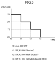
- FIG. 5 is a diagram illustrating an operation of the configuration example of FIG. 4 , and illustrates a relationship between a voltage of the port 12 a of the microcomputer 12 and ON/OFF of the switches SW_A 1 , SW_A 2 , and SW_A 3 .
- the voltage of the port 12 a is VCC, for example, 3 V.
- the switch SW_A 3 is turned ON (time t 1 )
- the voltage of the port 12 a is a voltage obtained by dividing VCC by R 1 and (R 2 +R 3 ), for example, 2 V.
- the voltage of the port 12 a is a voltage obtained by dividing VCC by R 1 and R 2 , for example, 1 V.
- the switch SW_A 1 is turned ON (time t 3 )
- the voltage of the port 12 a becomes GND (0 V).
- a control signal can be transmitted from the remote controller 20 A to the imaging device 10 by turning ON/OFF the switches SW_A 1 , SW_A 2 , and SW_A 3 . Therefore, for example, the operation of the imaging device 10 can be controlled from the remote controller 20 A such as a shutter operation by turning ON the switch SW_A 1 , a half shutter operation by turning ON the switch SW_A 2 , and a moving image recording operation by turning ON the switch SW_A 3 .
- the imaging device 10 includes the connector 11 having a USB TYPE-C terminal.
- the plurality of terminals of the connector 11 include the GND terminals 1 a , 1 b , 1 c , and 1 d .
- the USB circuit 15 communicates with the external device.
- the remote controllers 20 and 20 A that perform communication using the GND terminals 1 a and 1 d alone are connected to the connector 11 , the microcomputer 12 communicates with the remote controllers 20 and 20 A.
- the imaging device 10 can communicate with the remote controllers 20 and 20 A not having the communication interface of USB TYPE-C, via the connector 11 having the USB TYPE-C terminal. Therefore, remote controller control of the imaging device 10 can be performed without separately providing a dedicated terminal other than the connector 11 .
- the remote controllers 20 and 20 A can send a signal to the imaging device 10 by switching a resistance value between the GND terminals 1 a and 1 d and the GND terminals 1 b and 1 c.
- USB PD USB power delivery
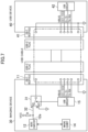
- FIGS. 6 and 7 are configuration examples including the imaging device according to the present embodiment.
- FIG. 6 illustrates a mode in which a remote controller is connected to the imaging device
- FIG. 7 illustrates a mode in which a USB device is connected to the imaging device.
- An imaging device 30 further includes a changeover switch 31 in addition to the configuration of the imaging device 10 described in the first embodiment.
- the changeover switch 31 is configured to be capable of switching a connection destination of the GND terminals 1 a and 1 d of the connector 11 to a node A or a node B.
- the node A is connected to the port 12 a of the microcomputer 12 via a wiring line 32 .
- the wiring line 32 is pulled up to the power supply VCC via the resistance element R.
- the node B is connected to the ground.
- the USB circuit 15 includes, for example, a detection IC conforming to the USB-PD standard such as a USB charging IC, and the detection IC detects whether or not the connected device is a USB-PD compatible device.
- the USB circuit 15 switches the changeover switch 31 to the node B side.
- the USB circuit 15 switches the changeover switch 31 to the node A side.
- the remote controller 20 shown in the first embodiment is connected to the connector 11 of the imaging device 30 .
- the USB circuit 15 switches the changeover switch 31 to the node A side.
- the imaging device 30 can perform an operation similar to that of the imaging device 10 described in the first embodiment. That is, a control signal can be transmitted from the remote controller 20 to the imaging device 30 by turning ON/OFF the switch SW_A 1 . Therefore, for example, a shutter operation of the imaging device 30 can be controlled from the remote controller 20 .
- a USB device 40 is connected to the connector 11 of the imaging device 30 via a USB cable.
- the USB device 40 includes a connector (receptacle) 41 of USB TYPE-C and a USB circuit 42 .
- the USB circuit 15 switches the changeover switch 31 to the node B side.
- the GND terminals 1 a and 1 d of the connector 11 are connected to the ground. Therefore, the imaging device 30 can communicate with the USB device 40 and supply power to the USB device 40 via the connector 11 .
- the imaging device 30 includes the connector 11 having the USB TYPE-C terminal.
- the plurality of terminals of the connector 11 include the GND terminals 1 a , 1 b , 1 c , and 1 d .
- the USB circuit 15 communicates with the USB device 40 when the USB device 40 is connected to the connector 11 .
- the remote controller 20 that performs communication using the GND terminals 1 a and 1 d alone is connected to the connector 11
- the microcomputer 12 communicates with the remote controller 20 .
- the imaging device 30 can communicate with the remote controller 20 not having the communication interface of USB TYPE-C, via the connector 11 having the USB TYPE-C terminal. Therefore, remote controller control of the imaging device 30 can be performed without separately providing a dedicated terminal other than the connector 11 .
- the imaging device 30 includes the changeover switch 31 .
- the changeover switch 31 connects the GND terminals 1 a and 1 d to the microcomputer 12 when the remote controller 20 is connected to the connector 11 , and connects the GND terminals 1 a and 1 d to the ground when the USB device 40 is connected to the connector 11 .
- the imaging device 30 can communicate with the USB device 40 and supply power to the USB device 40 , and thus can be compatible with USB PD.
- the remote controller 20 described in the first embodiment may be connected to the imaging device 30 . That is, the remote controllers 20 and 20 A can send a signal to the imaging device 30 by switching a resistance value between the GND terminals 1 a and 1 d and the GND terminals 1 b and 1 c.
- the remote controller has been described as an example of the external device other than the USB device connected to the USB TYPE-C connector of the imaging device, but the present disclosure is not limited thereto.
- the connector included in the imaging device has been described as USB TYPE-C, but the present disclosure is not limited thereto.
- the present disclosure can be applied to any connector that conforms to a predetermined standard and has a plurality of terminals including two or more GND terminals. That is, for the existing communication interface having two or more GND terminals as illustrated in FIG. 8 A , as illustrated in FIG. 8 B , one GND terminal may be used for another application (COMM), similarly to the above-described embodiment. As a result, a new communication line can be secured without adding a new interface connector to the imaging device.
- circuitry or processing circuitry including a general purpose processor, an application specific processor, an integrated circuit, application specific integrated circuits (ASICs), a central processing unit (CPU), a conventional circuit, and/or a combination thereof programmed to implement the described functions.
- a processor includes a transistor and other circuits, and is regarded as the circuitry or the processing circuitry.
- the processor may be a programmed processor that executes a program stored in a memory.
- circuitry, a unit, and an instrument are hardware programmed to implement the described functions or hardware executing the functions.
- the hardware may be any hardware disclosed herein or any hardware programmed to execute the described functions or known to execute the described functions.
- the circuitry is a processor regarded as a type of circuitry
- the circuitry, an instrument, or a unit is a combination of hardware and software used to configure the hardware and/or the processor.
- the present disclosure is applicable to an imaging device including a connector for connecting an external device.
Landscapes
- Engineering & Computer Science (AREA)
- Theoretical Computer Science (AREA)
- Physics & Mathematics (AREA)
- General Engineering & Computer Science (AREA)
- General Physics & Mathematics (AREA)
- Mathematical Physics (AREA)
- Computer Hardware Design (AREA)
- Studio Devices (AREA)
Abstract
Description
- This application claims priority to Japanese patent application No. 2023-143631 filed on Sep. 5, 2023, which is incorporated by reference in its entirety.
- The present disclosure relates to an imaging device including a connector to which an external device is connected.
- Conventionally, in a case of controlling an imaging device by using a wired remote controller, remote controller control has been performed by providing a dedicated terminal.
- JP 2018-45607 A discloses an electronic apparatus capable of detecting whether a connected external device is a TYPE-C device or a non-TYPE-C device. The electronic apparatus includes: a first terminal that receives power from an external device; a second terminal that acquires information on power supply capability of the external device; and a determination unit that determines a type of the external device on the basis of an order in which a voltage is applied to the first terminal and the second terminal.
- The present disclosure enables an imaging device including a connector conforming to a predetermined standard to communicate, via the connector, with an external device not including a communication interface of the predetermined standard.
- An imaging device according to the present disclosure includes: a connector conforming to a predetermined standard and having a plurality of terminals including first and second ground (GND) terminals; a first communication unit configured to communicate with a first external device having a communication interface of the predetermined standard when the first external device is connected to the connector; and a second communication unit configured to communicate with a second external device configured to perform communication using the first and second GND terminals alone among the plurality of terminals when the second external device is connected to the connector.
- The imaging device according to the present disclosure can communicate with an external device that does not have a communication interface of a predetermined standard, via a connector conforming to the predetermined standard.
-
FIG. 1 is an example of a terminal layout of a connector included in an imaging device according to an embodiment; -
FIG. 2 is a configuration example including the imaging device according to the first embodiment; -
FIG. 3 is an operation example of the configuration example ofFIG. 2 ; -
FIG. 4 is another configuration example including the imaging device according to the first embodiment; -
FIG. 5 is an operation example of the configuration example ofFIG. 4 ; -
FIG. 6 is a configuration example including an imaging device according to a second embodiment; -
FIG. 7 is a configuration example including the imaging device according to the second embodiment; and -
FIGS. 8A and 8B are a use mode of a connector according to another embodiment. - Hereinafter, embodiments will be described in detail with reference to the drawings as appropriate. However, unnecessarily detailed description may be omitted. For example, a detailed description of a well-known matter and a repeated description of substantially the same configuration may be omitted. This is to avoid unnecessary redundancy of the following description and to facilitate understanding by those skilled in the art. It is to be noted that the inventor(s) provides the accompanying drawings and the following description in order to enable those skilled in the art to fully understand the present disclosure, and does not intend to limit the claimed subject matter by them.
-
FIG. 1 is an example of a terminal layout of a connector included in an imaging device according to an embodiment. This connector is a connector of universal serial bus (USB) TYPE-C, and is an example of a connector conforming to a predetermined standard. As illustrated inFIG. 1 , in the connector of USB TYPE-C,GND terminals GND terminals - When an external device having a communication interface of USB TYPE-C is connected to the connector illustrated in
FIG. 1 , the imaging device communicates with the external device in accordance with the standard of USB TYPE-C. Furthermore, in the present embodiment, a remote controller that controls an operation of the imaging device can be connected to the connector ofFIG. 1 . The remote controller does not have a communication interface of USB TYPE-C, and communicates with the imaging device by using theGND terminals GND terminals GND terminals GND terminals GND terminals GND terminals -
FIG. 2 illustrates a configuration example including the imaging device according to the present embodiment. InFIG. 2 , animaging device 10 includes a connector (receptacle) 11 of USB TYPE-C. In theconnector 11, theGND terminals port 12 a of amicrocomputer 12 via awiring line 13. Thewiring line 13 is pulled up to a power supply VCC via a resistance element R. Themicrocomputer 12 controls an operation of animaging element 14 in accordance with a voltage of theport 12 a. Themicrocomputer 12 is an example of a second communication unit in the present disclosure. TheGND terminals - A
USB circuit 15 is connected to various pins of theconnector 11, and communicates with an external device having a USB TYPE-C communication interface when the external device is connected to theconnector 11. TheUSB circuit 15 is an example of a first communication unit in the present disclosure. - A
remote controller 20 includes a connector (plug) 21 of USB TYPE-C and a switch SW_A1 that can be turned ON and OFF from the outside. When the switch SW_A1 is ON, theGND terminals GND terminals GND terminals GND terminals GND terminals -
FIG. 3 is a diagram illustrating an operation of the configuration example ofFIG. 2 , and illustrates a relationship between a voltage of theport 12 a of themicrocomputer 12 and ON/OFF of the switch SW_A1. As illustrated inFIG. 3 , when the switch SW_A1 is OFF, theGND terminals GND terminals port 12 a is VCC. Whereas, when the switch SW_A1 is ON, since theGND terminals GND terminals port 12 a becomes GND. As a result, a control signal can be transmitted from theremote controller 20 to theimaging device 10 by turning ON/OFF the switch SW_A1. Therefore, for example, a shutter operation of theimaging device 10 can be controlled from theremote controller 20. -
FIG. 4 is another configuration example including the imaging device according to the present embodiment. In the configuration ofFIG. 4 , the configuration of theimaging device 10 is similar to the configuration illustrated inFIG. 2 . Thewiring line 13 is pulled up to the power supply VCC via a resistance element R1. - A
remote controller 20A includes theconnector 21 of USB TYPE-C, resistance elements R2 and R3, and switches SW_A1, SW_A2, and SW_A3 that can be turned ON and OFF from the outside. The resistance elements R2 and R3 are connected in series between theGND terminals GND terminals -
FIG. 5 is a diagram illustrating an operation of the configuration example ofFIG. 4 , and illustrates a relationship between a voltage of theport 12 a of themicrocomputer 12 and ON/OFF of the switches SW_A1, SW_A2, and SW_A3. As illustrated inFIG. 5 , when all the switches SW_A1, SW_A2, and SW_A3 are OFF (time t0), the voltage of theport 12 a is VCC, for example, 3 V. When the switch SW_A3 is turned ON (time t1), the voltage of theport 12 a is a voltage obtained by dividing VCC by R1 and (R2+R3), for example, 2 V. When the switch SW_A2 is turned ON (time t2), the voltage of theport 12 a is a voltage obtained by dividing VCC by R1 and R2, for example, 1 V. When the switch SW_A1 is turned ON (time t3), the voltage of theport 12 a becomes GND (0 V). - As a result, a control signal can be transmitted from the
remote controller 20A to theimaging device 10 by turning ON/OFF the switches SW_A1, SW_A2, and SW_A3. Therefore, for example, the operation of theimaging device 10 can be controlled from theremote controller 20A such as a shutter operation by turning ON the switch SW_A1, a half shutter operation by turning ON the switch SW_A2, and a moving image recording operation by turning ON the switch SW_A3. - As described above, according to the present embodiment, the
imaging device 10 includes theconnector 11 having a USB TYPE-C terminal. The plurality of terminals of theconnector 11 include theGND terminals connector 11, theUSB circuit 15 communicates with the external device. When theremote controllers GND terminals connector 11, themicrocomputer 12 communicates with theremote controllers - As a result, the
imaging device 10 can communicate with theremote controllers connector 11 having the USB TYPE-C terminal. Therefore, remote controller control of theimaging device 10 can be performed without separately providing a dedicated terminal other than theconnector 11. - Furthermore, the
remote controllers imaging device 10 by switching a resistance value between theGND terminals GND terminals - In a second embodiment, a configuration of an imaging device compatible with USB power delivery (USB PD) will be described. The USB PD is one of power supply standards corresponding to a USB TYPE-C terminal.
-
FIGS. 6 and 7 are configuration examples including the imaging device according to the present embodiment.FIG. 6 illustrates a mode in which a remote controller is connected to the imaging device, andFIG. 7 illustrates a mode in which a USB device is connected to the imaging device. - An
imaging device 30 further includes achangeover switch 31 in addition to the configuration of theimaging device 10 described in the first embodiment. Thechangeover switch 31 is configured to be capable of switching a connection destination of theGND terminals connector 11 to a node A or a node B. The node A is connected to theport 12 a of themicrocomputer 12 via awiring line 32. Thewiring line 32 is pulled up to the power supply VCC via the resistance element R. The node B is connected to the ground. - Switching control of the
changeover switch 31 is performed in accordance with a control signal output from theUSB circuit 15. TheUSB circuit 15 includes, for example, a detection IC conforming to the USB-PD standard such as a USB charging IC, and the detection IC detects whether or not the connected device is a USB-PD compatible device. When the USB device is connected to theconnector 11, theUSB circuit 15 switches thechangeover switch 31 to the node B side. Whereas, when an external device other than the USB device is connected to theconnector 11, theUSB circuit 15 switches thechangeover switch 31 to the node A side. - In the mode of
FIG. 6 , theremote controller 20 shown in the first embodiment is connected to theconnector 11 of theimaging device 30. Upon recognizing that an external device other than the USB device is connected to theconnector 11, theUSB circuit 15 switches thechangeover switch 31 to the node A side. As a result, theimaging device 30 can perform an operation similar to that of theimaging device 10 described in the first embodiment. That is, a control signal can be transmitted from theremote controller 20 to theimaging device 30 by turning ON/OFF the switch SW_A1. Therefore, for example, a shutter operation of theimaging device 30 can be controlled from theremote controller 20. - In the mode of
FIG. 7 , a USB device 40 is connected to theconnector 11 of theimaging device 30 via a USB cable. The USB device 40 includes a connector (receptacle) 41 of USB TYPE-C and aUSB circuit 42. Upon recognizing that the USB device 40 is connected to theconnector 11 through communication with theUSB circuit 42, theUSB circuit 15 switches thechangeover switch 31 to the node B side. Thus, theGND terminals connector 11 are connected to the ground. Therefore, theimaging device 30 can communicate with the USB device 40 and supply power to the USB device 40 via theconnector 11. - As described above, according to the present embodiment, the
imaging device 30 includes theconnector 11 having the USB TYPE-C terminal. The plurality of terminals of theconnector 11 include theGND terminals USB circuit 15 communicates with the USB device 40 when the USB device 40 is connected to theconnector 11. When theremote controller 20 that performs communication using theGND terminals connector 11, themicrocomputer 12 communicates with theremote controller 20. - As a result, the
imaging device 30 can communicate with theremote controller 20 not having the communication interface of USB TYPE-C, via theconnector 11 having the USB TYPE-C terminal. Therefore, remote controller control of theimaging device 30 can be performed without separately providing a dedicated terminal other than theconnector 11. - Furthermore, the
imaging device 30 includes thechangeover switch 31. Thechangeover switch 31 connects theGND terminals microcomputer 12 when theremote controller 20 is connected to theconnector 11, and connects theGND terminals connector 11. As a result, when the USB device 40 is connected to theconnector 11, theimaging device 30 can communicate with the USB device 40 and supply power to the USB device 40, and thus can be compatible with USB PD. - In the present embodiment, the
remote controller 20 described in the first embodiment may be connected to theimaging device 30. That is, theremote controllers imaging device 30 by switching a resistance value between theGND terminals GND terminals - As described above, the above embodiments have been described as examples of the technology disclosed in the present application. However, the technology in the present disclosure is not limited thereto, and can also be applied to embodiments in which changes, replacements, additions, omissions, and the like are made as appropriate. In addition, it is also possible to make a new embodiment by combining components described in the above-described embodiments.
- In the first and second embodiments, the remote controller has been described as an example of the external device other than the USB device connected to the USB TYPE-C connector of the imaging device, but the present disclosure is not limited thereto.
- Furthermore, in the first and second embodiments, the connector included in the imaging device has been described as USB TYPE-C, but the present disclosure is not limited thereto. The present disclosure can be applied to any connector that conforms to a predetermined standard and has a plurality of terminals including two or more GND terminals. That is, for the existing communication interface having two or more GND terminals as illustrated in
FIG. 8A , as illustrated inFIG. 8B , one GND terminal may be used for another application (COMM), similarly to the above-described embodiment. As a result, a new communication line can be secured without adding a new interface connector to the imaging device. - Functions implemented by components described herein may be implemented in circuitry or processing circuitry, including a general purpose processor, an application specific processor, an integrated circuit, application specific integrated circuits (ASICs), a central processing unit (CPU), a conventional circuit, and/or a combination thereof programmed to implement the described functions. A processor includes a transistor and other circuits, and is regarded as the circuitry or the processing circuitry. The processor may be a programmed processor that executes a program stored in a memory.
- In this specification, circuitry, a unit, and an instrument are hardware programmed to implement the described functions or hardware executing the functions. The hardware may be any hardware disclosed herein or any hardware programmed to execute the described functions or known to execute the described functions.
- In a case where the hardware is a processor regarded as a type of circuitry, the circuitry, an instrument, or a unit is a combination of hardware and software used to configure the hardware and/or the processor.
- As described above, the embodiments have been described as examples of the technology in the present disclosure. For this purpose, the accompanying drawings and the detailed description have been provided.
- Accordingly, some of the components described in the accompanying drawings and the detailed description may also include components that are not indispensable for solving the problem in order to exemplify the above technology in addition to indispensable components for solving the problem. Therefore, these components that are not indispensable are not to be immediately recognized to be indispensable on the basis of the fact that these components that are not indispensable are described in the accompanying drawings or detailed description.
- In addition, since the above-described embodiments are intended to exemplify the technology in the present disclosure, various changes, replacements, additions, omissions, and the like can be made within the scope of the claims or equivalents thereof.
- The present disclosure is applicable to an imaging device including a connector for connecting an external device.
Claims (4)
Applications Claiming Priority (2)
| Application Number | Priority Date | Filing Date | Title |
|---|---|---|---|
| JP2023143631A JP2025036949A (en) | 2023-09-05 | 2023-09-05 | Imaging device |
| JP2023-143631 | 2023-09-05 |
Publications (2)
| Publication Number | Publication Date |
|---|---|
| US20250077458A1 true US20250077458A1 (en) | 2025-03-06 |
| US12585603B2 US12585603B2 (en) | 2026-03-24 |
Family
ID=94774522
Family Applications (1)
| Application Number | Title | Priority Date | Filing Date |
|---|---|---|---|
| US18/814,648 Active US12585603B2 (en) | 2023-09-05 | 2024-08-26 | Imaging device |
Country Status (2)
| Country | Link |
|---|---|
| US (1) | US12585603B2 (en) |
| JP (1) | JP2025036949A (en) |
Citations (5)
| Publication number | Priority date | Publication date | Assignee | Title |
|---|---|---|---|---|
| US20030158977A1 (en) * | 2000-08-30 | 2003-08-21 | Jens Barrenscheen | Identification of a peripheral connection state with a universal serial bus |
| US20170220090A1 (en) * | 2016-01-29 | 2017-08-03 | Samsung Electronics Co., Ltd. | Universal serial bus power-delivery and system including the same |
| US20170344098A1 (en) * | 2016-05-26 | 2017-11-30 | Silicon Laboratories Inc. | Vconn Pull-Down Circuits And Related Methods For USB Type-C Connections |
| US20180067885A1 (en) * | 2016-09-08 | 2018-03-08 | Eever Technology, Inc. | Usb type-c module |
| US20200333998A1 (en) * | 2019-04-17 | 2020-10-22 | Samsung Electronics Co., Ltd. | Electronic device, audio-purpose external electronic device, and method of receiving signal by electronic device connected with audio-purpose external electronic device |
Family Cites Families (2)
| Publication number | Priority date | Publication date | Assignee | Title |
|---|---|---|---|---|
| JP6792389B2 (en) | 2016-09-16 | 2020-11-25 | キヤノン株式会社 | Electronic devices and control methods for electronic devices |
| JP2021092861A (en) | 2019-12-06 | 2021-06-17 | 東芝テック株式会社 | Electronic device |
-
2023
- 2023-09-05 JP JP2023143631A patent/JP2025036949A/en active Pending
-
2024
- 2024-08-26 US US18/814,648 patent/US12585603B2/en active Active
Patent Citations (5)
| Publication number | Priority date | Publication date | Assignee | Title |
|---|---|---|---|---|
| US20030158977A1 (en) * | 2000-08-30 | 2003-08-21 | Jens Barrenscheen | Identification of a peripheral connection state with a universal serial bus |
| US20170220090A1 (en) * | 2016-01-29 | 2017-08-03 | Samsung Electronics Co., Ltd. | Universal serial bus power-delivery and system including the same |
| US20170344098A1 (en) * | 2016-05-26 | 2017-11-30 | Silicon Laboratories Inc. | Vconn Pull-Down Circuits And Related Methods For USB Type-C Connections |
| US20180067885A1 (en) * | 2016-09-08 | 2018-03-08 | Eever Technology, Inc. | Usb type-c module |
| US20200333998A1 (en) * | 2019-04-17 | 2020-10-22 | Samsung Electronics Co., Ltd. | Electronic device, audio-purpose external electronic device, and method of receiving signal by electronic device connected with audio-purpose external electronic device |
Also Published As
| Publication number | Publication date |
|---|---|
| US12585603B2 (en) | 2026-03-24 |
| JP2025036949A (en) | 2025-03-17 |
Similar Documents
| Publication | Publication Date | Title |
|---|---|---|
| CN109490684B (en) | Apparatus and method for detecting leakage current generation condition in USB interface | |
| US11119550B2 (en) | USB device and operation method thereof | |
| JP4961999B2 (en) | Electronics | |
| US8156349B2 (en) | Electronic device and interface system | |
| WO2014123814A1 (en) | Method and system for detecting connection of a host device to an accessory device | |
| US10243386B2 (en) | Power supply circuit in electronic device and control method thereof | |
| CN110858711B (en) | Circuit and method for overvoltage protection in universal serial bus interface | |
| JP2015103256A (en) | System and method for detecting universal serial bus device | |
| US20200073349A1 (en) | Devices, control modules, and controllers | |
| JP2020008898A (en) | Electronic equipment | |
| JPH0894695A (en) | Semiconductor power switch system | |
| US10333585B1 (en) | Repeater device with a plurality of parameter configuration modes and parameter configuration method thereof | |
| US11181958B2 (en) | Electronic device with power source control ciruitry for determining a current | |
| CN214375036U (en) | Mobile device test system | |
| KR20010015076A (en) | Signal input and output apparatus | |
| US12585603B2 (en) | Imaging device | |
| JPH07183791A (en) | Integrated circuit, its circuit system, device used therewith, and method of using integrated circuit | |
| US11081840B2 (en) | Detection circuit applied to a connecting port | |
| JP2002290490A (en) | Electronics | |
| TWI768881B (en) | Sideband signal adjustment system and method thereof, and storage device | |
| US7679321B2 (en) | Power circuit | |
| US20180102618A1 (en) | Interface assembly that connects a peripheral device to an interface of a host system, an electronic device and a method of signaling | |
| US11121563B2 (en) | Power control circuit | |
| US20260118934A1 (en) | Usb power delivery management | |
| CN111404538B (en) | Connection circuit and connection method thereof |
Legal Events
| Date | Code | Title | Description |
|---|---|---|---|
| FEPP | Fee payment procedure |
Free format text: ENTITY STATUS SET TO UNDISCOUNTED (ORIGINAL EVENT CODE: BIG.); ENTITY STATUS OF PATENT OWNER: LARGE ENTITY |
|
| STPP | Information on status: patent application and granting procedure in general |
Free format text: DOCKETED NEW CASE - READY FOR EXAMINATION |
|
| AS | Assignment |
Owner name: PANASONIC INTELLECTUAL PROPERTY MANAGEMENT CO., LTD., JAPAN Free format text: ASSIGNMENT OF ASSIGNORS INTEREST;ASSIGNORS:TAKAHASHI, MASAYA;NISHIKAWA, KIN;REEL/FRAME:069456/0375 Effective date: 20240805 |
|
| STPP | Information on status: patent application and granting procedure in general |
Free format text: NON FINAL ACTION COUNTED, NOT YET MAILED |
|
| STPP | Information on status: patent application and granting procedure in general |
Free format text: RESPONSE TO NON-FINAL OFFICE ACTION ENTERED AND FORWARDED TO EXAMINER |
|
| STPP | Information on status: patent application and granting procedure in general |
Free format text: ALLOWED -- NOTICE OF ALLOWANCE NOT YET MAILED |
|
| STPP | Information on status: patent application and granting procedure in general |
Free format text: NOTICE OF ALLOWANCE MAILED -- APPLICATION RECEIVED IN OFFICE OF PUBLICATIONS |
|
| STPP | Information on status: patent application and granting procedure in general |
Free format text: PUBLICATIONS -- ISSUE FEE PAYMENT RECEIVED Free format text: PUBLICATIONS -- ISSUE FEE PAYMENT VERIFIED |
|
| STCF | Information on status: patent grant |
Free format text: PATENTED CASE |