US2024967A - Method and apparatus for rehabilitating peristalsis of the colon - Google Patents
Method and apparatus for rehabilitating peristalsis of the colon Download PDFInfo
- Publication number
- US2024967A US2024967A US639105A US63910532A US2024967A US 2024967 A US2024967 A US 2024967A US 639105 A US639105 A US 639105A US 63910532 A US63910532 A US 63910532A US 2024967 A US2024967 A US 2024967A
- Authority
- US
- United States
- Prior art keywords
- colon
- liquid
- pressure
- outlet
- applicator
- Prior art date
- Legal status (The legal status is an assumption and is not a legal conclusion. Google has not performed a legal analysis and makes no representation as to the accuracy of the status listed.)
- Expired - Lifetime
Links
Images
Classifications
-
- A—HUMAN NECESSITIES
- A61—MEDICAL OR VETERINARY SCIENCE; HYGIENE
- A61H—PHYSICAL THERAPY APPARATUS, e.g. DEVICES FOR LOCATING OR STIMULATING REFLEX POINTS IN THE BODY; ARTIFICIAL RESPIRATION; MASSAGE; BATHING DEVICES FOR SPECIAL THERAPEUTIC OR HYGIENIC PURPOSES OR SPECIFIC PARTS OF THE BODY
- A61H21/00—Massage devices for cavities of the body, e.g. nose, ears and anus ; Vibration or percussion related aspects A61H23/00
Definitions
- this action will massage and exercise the colon and the muscles 40 thereof and will reeducate the colon to perform its normal perlstaltic action.
- The'applicator and the flexible hose are preferably of a relatively large diameter and form a continua- 50, non cf the ccicn. 'rms nexibie'ncsc 1s connected to a means whereby a positive pressure or a negative pressure may be produced or. in other words, whereby a positive pressure (above zero) or a negative pressure (a vacuum) may be produced.
- I utilize a liquid, such as water, which is injected into the colon through the iiexiblehose and is caused to entirely fill vthe colon.
- the pressure producing means is then actuated in order to develop a suit- 5 able pressure and in order to expand the colon to its normal expanded size. It is not the purpose of my invention to dilate. the colon by overexpansion, but merely to expand same to its nor- ⁇ mal expanded size.
- the colon may be contracted by use of a vacuum of substantially four inches of vacuum. 5
- the entire colon is contracted and the muscles which ordinarily perform the peristaltic action are caused to contract.
- the muscles which lcontrol or produce the peri- 50 staltio action are caused tomcve in thesame manner in which they move when they function ofI their own accord and under normal conditions.V
- I utilize liquid as a pressure-transmitting means.
- the applicator is inserted but a .short distance beyond the rectal sphincter.
- This is an important part of my invention, and my invention isto be clearly distinguished from the ordinary devices for colon irrigation in which a flexible tube is extended through the colon and the outlet end thereof placed, if possible, in the caecum.
- My invention is not an irrigating apparatus, but a method and apparatus for exercising the colon and for rehabilitating peristalsis. In order that the entire colon may be treated, it is highly desirable that the applicator extend but a minimum distance into the colon, thus subjecting the entire colon to the treatment of the hydraulic massage.
- the flexible tube is relatively large and may be said to form a continuation ofthe colon. Obviously, however, -a smaller size tube mightvbe used if desired.
- the preferred form of ⁇ my invention includes steps o f the process and means in the apparatus whereby a supply of liquid may be inserted in the colon and the portion of the colon up to the obstruction ⁇ b e worked loose.
- This object of my invention is accomplished by the use of a pressure andrvacuum gauge which is connected toa column of-liquid which extends through the flexible tube ⁇ and into the colon. By controlling the pressure of the liquid or the vacuum placed on the liquid it is possible to control the expansion or contraction of the colon. It
- colon may be over-expanded and this may in ;Q'
- I provide a gauge Vwhich determines the pressure
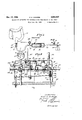
- Fig. l is a view illustrating partly in section a form of niy invention which is utilized solely for performing the massaging operation on the colon.
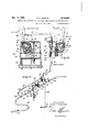
- Fig. 2 is a diagrammatic view illustrating another form of my invention which may be utilized not only for massaging. the colon, but also for the purpose of removing obstructions from the colon in order that the entire colon may be treated with my apparatus.
- Fig. 3 is a sectional view taken through a part of vmy invention which includes the various control mechanisms.
- Fig. 4 is a section taken on the. line 4--4 of Fig. 3. y
- Fig. 5 is a section taken on the line 5-5 of Fig. 3.
- the numeral II represents a flexible tube having an applicator I2 secured to the end'thereof.
- This applicator I2 is adapted to be inserted into the rectal portion I4 of a colon generally designated by the numeral I5.
- the applicator is relatively short and extends but a slight distancebeyond the rectal sphincter I6.
- the flexible tube II is connected by a short pipe I'I to a liquid supply means .I9 which is in the form of a cylinder.
- the cylinder may be re-supplied with liquid through an opening 20 which is ordinarily closed ..by a plug, as shown. Operable in the cylinder rotating the gear 26 in a suitable direction the.
- piston 22 may be moved to the left or to the right, as desired.
- a pressure indicating means 29 Connectedto the pipe I'l is a pressure indicating means 29 which is adapted to indicate a positive pressure or alnega'tive'pressure of the fluid in the pipe Il, and consequently to indicate 55 the pressural condition in the colon.
- This pressure indicating means is in the form 'of a lgauge having mechanism-whereby a positive pressure or a negative pressure or vacuum may be indicated thereon.
- the colon is ordinarily previously cleansed of all obstructions in order that the entire colon may b e accessible for the massaging treatment of my invention.
- the crank 28 is operated to move the cated on the pressure indicating means 29.
- the l pressure at the pipe II is substantially the same as the pressure in any part of the colon.
- This the cylinder I9 is immediately transmitted through the liquid in the pipe I1 and the tube II to the liquid in the colon.' Furthermore, due to the fact that a pressure of the liquid is equal in 5 al1 directions, the pressure in all parts of the colon is substantially the same.A As the pressure increases on the liquid in the colon I5 the colon is gradually expanded.
- the colon therefore has been caused by artificial means to first expand and thereafter to contract in substantially the same mannery as 30 this expansion and .contraction is normally performed byreason of the peristaltic action.
- This operation of my apparatus is continued for a number of times, and the colon is alternately expanded and contracted.
- the nuneral 30 represents a housing in which various parts of the control mechanism of this form of my invention are located.
- This housing consists of a 15 cover portion 3
- an inlet pipe 34 whichconstitutes a part of the inlet of this form of my invention.
- the right end of the inlet pipe 34 has an upwardly extending nipple 35 which is located exterior of the housing 39, and adapted to be connected thereto is a flexible hose 36 which is connected to a suitable percolator 31, as shown in Fig. 5.
- the left end of the inlet pipe 34 has a horizontally extending nipple 36 which projects from the left end of the housing 39.
- an inlet valve 39 which has a valve stem 49 extending downward therefrom, which valve stem is connected to a closure member on the Ainterior of the inlet valve.
- is an operating lever 42 which is connected at'one end to the valve stem 40 and at the other end to a vertically extending rod 43, which is normally supported in a raised position by means of a. spring 44 which is compressed between a flange 45 at the upper end of the rod 43 and a wall 46 provided ⁇ by a socket 41 of the housing 39.
- outlet pipe 53 which forms a part of the outlet of the invention.
- This outlet pipe 53 has an outwardly extending nipple 54 at the right end thereof, which projects to the .exterior of the housing 33 and is adapted for connection to a discharge hose 55 .which is preferably connected to a sewer.
- the left end of the'outlet pipe .53 has a nipple 56 which projects outwardly in a horizontal direction pipe 15 which is preferably a water pipe.
- a gate 69 which is movable in the chamber 6
- valve 64 which will permit a flow of liquid in. an outward or rightward direction, but which has a gate 65 which closes to prevent a flow of liquid in a leftward or inward direction.
- a pressure indicating means in the form o a gauge 61.
- the gauge 61 is connected to the upper part of the check valve body 63 by means of a small pipe or tube 69.
- the gauge 61 is of common design in which the pressure and vacuum may be indicated. Pressure in.- dcations 19 appear on one side of the face oi' the gauge, while vacuum indications 1
- a upper' portion of this water pipe is extended horizontally and is vconnected to an injector control valve 16 which is shown best in Fig. 5.
- This injector control valve includes a relatively large chamber 11 in which there is positioned a spring 13 for holding a valve member 13 against a seat.
- a check Extending upwardly from this valve member 19 to the exterior of the body of the valve is an operating stem 89. By depressing the operating stem 69 the valve is opened.
- Fan operating lever 32 Supported by an arm 6
- 'I'he other end of this operating lever 62' is provided y with a downwardly extending cam formation which extends around a cam pin ⁇ 66 connected to the lever 62.
- the injector control 15 valve 16 has connected to the outletside thereof a relatively small pipe or tube 9
- This injector 92 includes a body 93 having a passage 94 therethrough. Connected to 20 I the passage. 94 is a small injector passage or opening 95 with which the tube 9
- the inlet pipe 15 includes a control valve 96 in order that 30 the pressure of the water passing to and through the injector 92 may be controlled, and in this manner the amount of vacuuin produced in the inlet pipe 53 may be governed.
- This form of my invention includes a flexible 35 tube
- Connected to the flexible tube is a T-iitting
- 92 is connected by a short section '
- This short section includes rubber tubes
- the T-iitting has a relatively smallpipe
- the perco- 50 lator 31 is filled with the desired solution or liquid which isv at the proper temperature.
- a clamp is then applied to the flexible tube .
- the lever 62 is then moved from full line position in Fig. 5 into the position indicated by dotted lines 33. When in this position the injectorcontrol valve is open and 'a suction is imposed on the outlet pipe 60 53. thevacuum or negative pressure thus produced being indicated on the gauge 61.
- the valve 96 in the water pipe 15 is then regulated so that the pressure and velocity of the water passing through the injector 32 is suiiicient to produce the 05 desired vacuum.
- the lever 62 at this time is moved into position indicated by dotted lines H0 of Figs. 4 and 5.
- the gate -60 closes the outlet pipe 53.
- the lever 62 is i full line position the gate 60 is in open positio and the outlet pipe 53 is unobstructed.
- the full line position of the lever 62 will be referred to as the return flow position while the dotted line position' i I0 will be referred to as the retention stop position of the lever.
- 'Ihis will expel all of the air from the inlet part of the apparatus and fromthe iiexible tube
- the clamp is then reapplied to close the flexible tube near the applicator.
- the applicator is then inserted into the rectal portion of the colon, as pointed out in connection with the form of my invention shown in Fig. 1.
- the clamp is then removed from the ilexible tube
- the operator watches the gauge 61 and when a pressure starts to register the foot pedal 60 is released and the lever 62 is moved from retention stop position toa position indicated'by dotted lines 88 in order to produce a vacuum in the outlet of the apparatus.
- retention stop position as shown by dotted lines lill, and the foot pedal i) is again depressed to admit fluid into the patient.
- the pressure gradually builds up, which pressure is indicated by the gauge 61. The.
- My invention is'intended -rst to expand and thereafter to contract the colon in order to produce an expansion and contraction therein which resembles the normal expansions and contractions produced involuntarily when the normal peristalticaction occurs.
- the applicator I2 or the applicator IUI is inserted but a short distance in order that the entire colon may be available for treatment.
- 00 are relatively large in diameter, and in fact may be considered asl constituting a continuation. of the colon. When preparing the colon for treatment the bowel. However, these operations are only.
- my invention is not an irrigating apparatus in any sense of the word, and usually theexerci'so5 ing of the colon is performed without removing considerable feces'which may adhere to the walls of the colon.
- My invention has for its object to rehabilitate or stimulate 7o peristalsis, and'this is accomplishedfby the expanding and contracting" thereof, which in a measure reeducates the bowel to perform its nor- "mal functions. Ordinarily, thefprocess is yperformed without removing considerable feces and u after the treatment has been completed the patient is sent to stool.
- the particular arrangement of the'v parts of the form of my invention disclosed in Figs. 2 to 5 inclusive constitutes an important part of my invention.
- the apparatus is susceptible of easy and convenient control. The introduction of the liquid is controlled by a foot lever while the removal of the liquid is controlled by a hand lever.
- a very important part of my invention is that it is unnecessary to sterilize the interior parts of the apparatus. This is due to the novelarrangement which I have produced. It will be seen that the only portion of the apparatus where there is a reverse flow, that is where there is an iniiow and an outflow, is the head portion of the T-fltting
- an applicator adapted to be inserted into at least the rectal portion of the colon and providing a relatively tight seal with the rectal sphincter; a liquid inlet means connected to said applicator i'or supplying liquid to said' colon under vsufficient pressure to expand'said colon; an outlet means connected to said applicator through which liquid may be withdrawn from said colon; an inlet valve means for closing said liquid inlet means; an outlet valve means for closing said outlet means; means for registering both the positive and negative pressures'in said colon; and means for withdrawing liquid from said colon through said outlet means under sufilcient negative pressure to contract said colon.
- the combination oi': an applicator adapted to be inserted into at least the rectal portion of the colon and providing a relatively tight seal with the rectal sphincter; a liquidv inlet means connected to said applicator for supplying liquid to said colon under suilicient pressure to expand said colon; an outlet means connected to' said applicator through which liquid may be withdrawn from said colon; an inlet valve means for closing said liquid inlet me'ans; an outlet valve means for said applicator for supplying liquid to said colon under suillcient pressure to expand said colon; an outlet means connected to said applicator through which liquid may be withdrawn from said colon; an inlet valve means for closing said liquid'inlet means; an outlet valve means for closing said outlet means; means connected to said apparatus so as to be in communication with said colon at all times for registering peristaltic action in -said colon; and means for withdrawing liquid 10 from said colon through said outlet means under' sufficient negative pressure to contract said colon.
- an applicator adapted to be inserted into at least the rectal portion of4 the l5 colon and providing a relatively tight seal with the'rectal sphincter; a liquid inlet means connected to said applicator for supplying liquid to said colon under sufcient pressure to expand said colon; an outlet means connected to said appllcator through which liquid may be withdrawn fromsaid colon; an inlet valve means for closing said liquid inlet means; an outlet valve means for closing said outlet means; means connected to said outlet means on the intake ⁇ side of said outlet valve means for registering peristaltic action in said colon; and means for withdrawing liquid from said colon through said outlet means under suillcient negative pressure to contract said colon.
- an applicator adapted to be in ⁇ serted into at least lthe rectal portion of the colon and providing a relatively tight seal with the rectal sphincter; a liquid inlet means connected to said applicator for supplying liquid to said vcolon under suillcient pressure to expand said colon; an outlet means connected to said applicator through which' liquid may be withdrawn from said colon; an inlet valve means for closing said 40 liquid inlet means; an outlet valve means for closing said outlet means; means connected to said outlet means on the intake side .of said outlet valve means for registering both the positive and negative pressuresin said colon; and means for withdrawing liquid from said colon throughV said outlet means under suiilcient negative pres-i sure to contractsaid colon.
- an applicator adapted to bein-- serted into at least the rectal portion oi' the colon 7 and providing a relatively tight seal with the rectal sphincter; a liquid inlet means connected to' said applicator for supplying liquid to said colon under suilicient pressure to expand said colon;
- outlet means connected to said applicator through which liquid may be withdrawn from said colon; valve means for closing said inlet means and said outlet means in order to lock the liquidpin said colon; means for registering peristaltic action in said colon while said liquid is so locked in said colon; and means for withdrawing liquid from said colon through said outlet means under suiicient negative pressure to contract said colon.
- an applicator adapted to be in-v serted into at least the rectal portion of the colon and providing a relatively tight seal with the rectal sphincter; a liquid inlet means connected to said applicator for supplying liquid to said colon under suillcient pressure to expand said colon; an outlet means connected yto said applicator through which liquid maybe withdrawn from said colon; an inlet valve means for closing said liquid inlet means; an outlet valve means for closing said outlet means, said liquid being locked in said colon when both said inlet valve means and said outlet valve means are closed; means for registering peristaltic action in said colon while said liquid is so locked in said colon; and means for withdrawing liquid from said colon through said outlet means under suiiicient negative pressure to contract said colon.
- an applicator adapted to be inserted into at least the rectal portion of the colon and providing a relatively tight seal with theV rectal sphincter; a liquid inlet means connected to said applicator for supplying liquid to said f vcolon under suflicient pressure to expand said colon; an outlet means connected to said applicator through which liquid may be withdrawn from said colon; an inlet, valve means for closing said liquid inlet means; an outlet valve means y for closing said outlet means, said liquid being locked in said colon when both said inlet valve means and said outlet valve means are closed;
Description
H. E. DIERKER Dec. 17, 193.5.
METHOD AND APPARATUS FOR REHABILITATING PERISTALSIS OF THE COLON 2 sheets-shawl Filed O Ct. 22, 1932 Vn cua/fo Dec. 17, 1935. H. E, DIERKER 2,024,967
METHOD AND APPARATUS FOR REHABILITATING PERISTALSIS OF THE COLON Filed Oct. 22, 1932 2 Sheets-Sheet 2 /Nz//vrae ,60 Haar-f 0156.552
Patented Dec, 17, 1935 AND APPARATUS FOR REHAB-ILI- TA'TING PERISTALSIS OF THE COLON Hugh E. Dierker,- Hollywood, Calif. Application October 22, 1932Serial No. 639,105
10 Claims. l(101. 12S-227) My invention relates to colonic `therapy and.
consists of a v method and apparatus for rehabilitating peristalsis of the colon. This application is a continuation in part of my application entitled Colon irrigation, Serial No. 474,784, filed Aug. 12, 1930, and which issued as Patent No. 1,910,756 on May 23, 1933. A l In order that the principles of my invention and its manner of operation may be more lucidly y understood, I will briefly refer tothe actions which occur in the alimentary canal and particularly the colon, and the various abnormal conditions which exist in the colon. It is the general'object of my invention to provide a method and apparatus for stimulating or rehabilitating normal peristalsis in order that the 'colon may function properly and in order that the residual products of digestion may be properlyiemptied from the colon. It is an object of my invention to vprovide a method and apparatus whereby thecolon may be internally massaged, preferably by hydraulic means in order that the muscles thereof may be exercised and vitalized, thus encouraging these muscles to function'in accordance with the usual laws of nature controlling the peristaltic action which occurs under normal conditions.
It is a further object of my invention to provide a method and apparatus whereby the colon may be expanded and contracted within its normal limits in order to exercise same and in order to stimulate andrehabilitate the muscles of the colon in order that the same may be reeducateclto perform the peristaltic action. y 3" It is a very important object of my invention to provide a method and an apparatus whereby the entire colon may be expanded and contracted.
As pointed out heretofore, this action will massage and exercise the colon and the muscles 40 thereof and will reeducate the colon to perform its normal perlstaltic action.
In the preferred form of`my invention I connect suitable pressure-producing means to the colon. This is preferably accomplished by using a flexible hose and an applicator on the end thereof which is inserted in the rectum a short distance beyond the rectal sphincter. The'applicator and the flexible hose are preferably of a relatively large diameter and form a continua- 50, non cf the ccicn. 'rms nexibie'ncsc 1s connected to a means whereby a positive pressure or a negative pressure may be produced or. in other words, whereby a positive pressure (above zero) or a negative pressure (a vacuum) may be produced.
In the preferred form of my invention I utilize a liquid, such as water, which is injected into the colon through the iiexiblehose and is caused to entirely fill vthe colon. The pressure producing means is then actuated in order to develop a suit- 5 able pressure and in order to expand the colon to its normal expanded size. It is not the purpose of my invention to dilate. the colon by overexpansion, but merely to expand same to its nor-` mal expanded size. This is very effectively ac- 10 complished in my method and by the apparatus which I provide as a part of vmy invention due y to the fact that when a pressure is applied tothe liquid in the pressure-applyingineans, this same pressure is automatically transferred through- 15- out the entire body of liquid which extends through the flexible tube and throughout the entire length of the colon. It is well known in physics that the pressure of a liquid is equal in all directions; therefore, by placing this liquid o under pressure I am able toproduce a pressure throughout the entire length of the colon which is substantially equal at all points and equal in all directions. I have found by performing numerous tests that from four to eight ounces 25 4 of pressurel are suflicient to properly expand the i colon. In' my method, therefore, I apply to the liquid by the pressure-producing means a pressure of not more than eight ounces. The next step 4in my method is -to contract the colon, thus o v contracting it or reducing it to its smallest size which it ordinarily occupies when it is contracted by the normal peristaltic4 action. This is accomplished by operating the pressure-producing means in such a manner that the pressure u in the colon is reduced to below zero pressure. This, in the form of my invention which utilizes the liquid as the 'pressure-transmitting medium. is accomplishedby withdrawing the liquid from the colon and by causing a vacuum to exist thereo in. In experimenting my invention and in using same over a period of time, I have determined that the colon may be contracted by use of a vacuum of substantially four inches of vacuum. 5 When this operation is performed' the entire colon is contracted and the muscles which ordinarily perform the peristaltic action are caused to contract. In other words,"by internal means the muscles which lcontrol or produce the peri- 50 staltio action are caused tomcve in thesame manner in which they move when they function ofI their own accord and under normal conditions.V Upon contracting the colon. it is then expanded,
and mistreatment is continued and the cclcn es.
' colon.
In the preferred form of my invention, as previously pointed out, I utilize liquid as a pressure-transmitting means. I prefer to use liquid, due to the fact that it is easy to inject, that the pressure thereof is equal in all directions in order that the entire colon may be treated and that the liquid may be readily removed, and furthermore, that the liquid is absolutely unharmful to the colon.
As previously pointed out, the applicator is inserted but a .short distance beyond the rectal sphincter. This is an important part of my invention, and my invention isto be clearly distinguished from the ordinary devices for colon irrigation in which a flexible tube is extended through the colon and the outlet end thereof placed, if possible, in the caecum. My invention is not an irrigating apparatus, but a method and apparatus for exercising the colon and for rehabilitating peristalsis. In order that the entire colon may be treated, it is highly desirable that the applicator extend but a minimum distance into the colon, thus subjecting the entire colon to the treatment of the hydraulic massage. In order that there may be a free flow of liquid into the colon and'out of the colon, during the performance of my invention the flexible tube is relatively large and may be said to form a continuation ofthe colon. Obviously, however, -a smaller size tube mightvbe used if desired.
By performing my invention, as previously pointed out, it is possible to loosen old encrustations of. mucus and feces and to work-free the contents of pockets and diverticula, which as is well known in colon therapy, adhere to the walls of the colon and constitute' a source of parasitic f vide a method and apparatus for stimulating 'or rehabilitating normal peristalsis in which ob structions in the colon may be removed prior to the actual performance of the hydraulic massage on the entire colon.
In view. of the fact that it is frequently necessary to remove such obstructions from the colon, the preferred form of` my invention includes steps o f the process and means in the apparatus whereby a supply of liquid may be inserted in the colon and the portion of the colon up to the obstruction `b e worked loose.
delivered to the drain. It is found that in the performance oi' this form of my invention a consecutive expansion and contraction of the colon will break away the obstruction, and in a short period of time the -obstructions in the colon may be removed. Many case records are available to prove that by my method and apparatus old incrustations of mucus, contents of pockets and diverticula, and definite bowel obstructions may When the colon has had all ob- 10 structions .removed therefrom and the liquid may pass to the upper end of the colon, the hydraulic massage of my invention may be performed, as pointed out heretofore.
It is highly desirable to control the amount of 15 expansion and amount of contraction ofthe colon. In some cases it ls absolutely necessary.` For example, whereAv the colon is infected or otherwise weakened, an over-expansion or contraction might cause a rupture thereof. 20
It is therefore an object of my invention to provide a method and apparatus in which the expansion and contraction of the colon may be controlled and over-expansion or over-contraction prevented.
This object of my invention is accomplished by the use of a pressure andrvacuum gauge which is connected toa column of-liquid which extends through the flexible tube` and into the colon. By controlling the pressure of the liquid or the vacuum placed on the liquid it is possible to control the expansion or contraction of the colon. It
colon may be over-expanded and this may in ;Q'
certain cases cause temporary paralysis'or atonicy of the colon and may-increase rather than eliminate constipation.
As suggested heretofore, it is possible to stimu- Ylate and rehabilitate peristalsis, and in the usual .1;
course of the method such peristalsis is rehabilitated before the process is stopped.
It is an object of my present invention, therefore, to provide a method and apparatus whereby y peristaltic action of the colon may be induced 51)' and the strength of the peristaltic action may be measured. In the preferred form of my invention I provide a gauge Vwhich determines the pressure,
- either positive or negative, of. the column of liquid which extends into the colon. By filling the -colon with liquid and then opening the outer end vof the flexible tube in order that. the colon may of its initiative force liquid therefrom, I am able to observe by the action of the gauge whether or not any peristalsis occurs. If peristalsis occurs 60 in the colon it will occur by alternate contractions and expansions. As the colon contracts and .expands a pressure is applied to the liquid, and since this pressure is equal in all directions the pressure is transmitted through the gauge. this pressure changes, an indication is made on the gauge and therefore the operator may observe whether or not the colon has been massaged and exercised to such an extent that peristalsis has been rehabilitateds, y g Other objects and advantages of my invention reside in the details of construction in the apparatus of my invention. ,These details relate to various mechanical improvements and in yvarious elements connected together in such a manner is due to the fact that the pressure applied in that the apparatus is always operated with safety to the patient. These additional objects and advantages will be clearly pointed out in the description ofthe details of my invention.
Referring to the drawings in which I have illustrated the construction of my invention:
Fig. l is a view illustrating partly in section a form of niy invention which is utilized solely for performing the massaging operation on the colon.
Fig. 2 is a diagrammatic view illustrating another form of my invention which may be utilized not only for massaging. the colon, but also for the purpose of removing obstructions from the colon in order that the entire colon may be treated with my apparatus.
Fig. 3 is a sectional view taken through a part of vmy invention which includes the various control mechanisms.
Fig. 4; is a section taken on the. line 4--4 of Fig. 3. y
Fig. 5 is a section taken on the line 5-5 of Fig. 3.
I will now refer to Fig. 1 of the drawings and describe the form of -my invention disclosed therein, and also the process of my invention which is performed thereby.
Referring to this figure, the numeral II represents a flexible tube having an applicator I2 secured to the end'thereof. This applicator I2 is adapted to be inserted into the rectal portion I4 of a colon generally designated by the numeral I5. It will be noted that the applicator is relatively short and extends but a slight distancebeyond the rectal sphincter I6. yThe flexible tube II is connected by a short pipe I'I to a liquid supply means .I9 which is in the form of a cylinder. The cylinder may be re-supplied with liquid through an opening 20 which is ordinarily closed ..by a plug, as shown. Operable in the cylinder rotating the gear 26 in a suitable direction the.
Connectedto the pipe I'l is a pressure indicating means 29 which is adapted to indicate a positive pressure or alnega'tive'pressure of the fluid in the pipe Il, and consequently to indicate 55 the pressural condition in the colon. This pressure indicating means is in the form 'of a lgauge having mechanism-whereby a positive pressure or a negative pressure or vacuum may be indicated thereon.
In this form of my invention the colon is ordinarily previously cleansed of all obstructions in order that the entire colon may b e accessible for the massaging treatment of my invention. After' the'applicator has been inserted, as previously explained; the crank 28 is operated to move the cated on the pressure indicating means 29. The l pressure at the pipe IIis substantially the same as the pressure in any part of the colon. This the cylinder I9 is immediately transmitted through the liquid in the pipe I1 and the tube II to the liquid in the colon.' Furthermore, due to the fact that a pressure of the liquid is equal in 5 al1 directions, the pressure in all parts of the colon is substantially the same.A As the pressure increases on the liquid in the colon I5 the colon is gradually expanded. When a pressure of substantially eight`ounces is indicated on the pressure indicating means 29 the colon will have been expanded to its normal outer limit, and it will be undesirable to place additional pressure on the liquid, since it might result in an overeexpansion of the colon. The crank 28 is then operated 15 in a reverse direction and the piston 22 is moved to the right. The effect is to withdraw liquid from the colon and suck same into the cylinder I9. When all the liquid has been withdrawn from the colon a further rightward movement of the 20 piston22 will producea vacuum on the colon and will contract same. I The vacuum or negative pressure produced on the colon will be indicated by the pressure indicating means. Upon com` pleting this negative pressure operation one cycle 25 of the process has been performed. T'he colon has been expanded and has thereafter been contracted. The colon therefore has been caused by artificial means to first expand and thereafter to contract in substantially the same mannery as 30 this expansion and .contraction is normally performed byreason of the peristaltic action. This operation of my apparatus is continued for a number of times, and the colon is alternately expanded and contracted. As pointed out heretofore, it is sometimes possible to rehabilitate or stimulate peristaltic action during the treating of the colon. In the apparatus of myI invention it is possible to determine whether or not such peristaltic action has been rehabilitated or stimu- 40 lated. This is accomplished by moving the piston 22 in a rightward direction in order to relieve the pressure thereon. In other words, the piston 22 may be moved in a rightward direction until the gauge 29 indicates a substantially zero pressure. 45 At this time there is no artificial pressure on the liquid in the colon and if a'y peristaltic action occurs the colon will of itself'tend to force the liquid from the colon, thus increasing the pressure of the liquid, which pressure is immediately transmitted through the-tube II in the pipe I1 and will be indicated on the 'pressure indicating means 29. I f the pressure indicating means 29 is closely observed and if any peristaltic action occurs fluctuations will be noted thereon.
The form of my invention which I have Just described in detail does not include any means whereby obstructions may be removed from the colon, although the samev is capable of removing incrustations of mucus and the contents of pock- 30 ets or diverticula. v
I will now describe a form of my invention which is designed to remove obstructions from the colon-and which is particularly designed for treating various colon disorders in which a conc5 striction exists in the colon, so that it is necessary by massaging -the colon to gradually relieve the constriction so that the entire colon may be treated. This condition often exists in cases of atonic constipation, spastic constipation, ptosis or bowel adhesions. 1
Referring to Figs. 2 to 6 inclusive the nuneral 30 represents a housing in which various parts of the control mechanism of this form of my invention are located. This housing consists of a 15 cover portion 3| and a base portion 32 which may be mounted on any suitable table 33. Situated in the upper part of the housing 39 is an inlet pipe 34 whichconstitutes a part of the inlet of this form of my invention. The right end of the inlet pipe 34 has an upwardly extending nipple 35 which is located exterior of the housing 39, and adapted to be connected thereto isa flexible hose 36 which is connected to a suitable percolator 31, as shown in Fig. 5. The left end of the inlet pipe 34 has a horizontally extending nipple 36 which projects from the left end of the housing 39. Located in the inlet pipe 34 is an inlet valve 39 which has a valve stem 49 extending downward therefrom, which valve stem is connected to a closure member on the Ainterior of the inlet valve. Supported by a'bracket 4| is an operating lever 42 which is connected at'one end to the valve stem 40 and at the other end to a vertically extending rod 43, which is normally supported in a raised position by means of a. spring 44 which is compressed between a flange 45 at the upper end of the rod 43 and a wall 46 provided` by a socket 41 of the housing 39. lExtending downwardly from the rod 43 is another rod 49, which is connected as shown in Fig. 2 to a foot pedal 59. By depressing the foot pedal 59 the rods 49 and 43 are moved downwardly against the action of the spring 44, and the lever 42 is moved in a clockwise direction in order to open the inlet valve and to allow liquid to flow through the inlet of the apparatus.
Also positioned in the housing 39 is an outlet pipe 53 which forms a part of the outlet of the invention. This outlet pipe 53 has an outwardly extending nipple 54 at the right end thereof, which projects to the .exterior of the housing 33 and is adapted for connection to a discharge hose 55 .which is preferably connected to a sewer. The left end of the'outlet pipe .53 has a nipple 56 which projects outwardly in a horizontal direction pipe 15 which is preferably a water pipe. The
from the housing, as shown. Included in the outlet pipe 53 is an outlet valve 51, the internal construction of which is shown in Fig. 4. Pivoted on a shaft 53 is a gate 69 which is movable in the chamber 6| of the outlet valve from a closed io an open position. The movement of the gate 69 is accomplished by swinging a lever 62 which is secured to tjhe shaft 53 on the exterior of the outlet valve 51.
Extending upwardly into the housing 39 is a upper' portion of this water pipe is extended horizontally and is vconnected to an injector control valve 16 which is shown best in Fig. 5. 'This injector control valve includes a relatively large chamber 11 in which there is positioned a spring 13 for holding a valve member 13 against a seat.
Also located in the outlet pipe 53 to the left of the outlet valve 51 is a check Extending upwardly from this valve member 19 to the exterior of the body of the valve is an operating stem 89. By depressing the operating stem 69 the valve is opened. Supported by an arm 6| isfan operating lever 32 having an end 33 5 adatepd to engage the operating stem/69. 'I'he other end of this operating lever 62' is provided y with a downwardly extending cam formation which extends around a cam pin` 66 connected to the lever 62. When the leverv 62 is moved 10 from full line position in Fig. 5 into a position indicated by broken lines 66 the operating. lever 82 is swung into a position indicated by dotted lines 69, thus depressing the stem 39 and opening the valve member 19. The injector control 15 valve 16 has connected to the outletside thereof a relatively small pipe or tube 9| which is connected to an injector 92 positioned in the outlet pipe 53. This injector 92 includes a body 93 having a passage 94 therethrough. Connected to 20 I the passage. 94 is a small injector passage or opening 95 with which the tube 9| is connected. By opening the injector ccntrolvvalve 16 a stream I of liquid is passed through the tube 9|; the small opening 95 and into the interior of the injector 25 body 93. In ,viewvof the directing oi this stream of liquid in an outward directionl a suction isl created in the outlet pipe 53 on the left side of the injector body of the injector 92. The inlet pipe 15 includes a control valve 96 in order that 30 the pressure of the water passing to and through the injector 92 may be controlled, and in this manner the amount of vacuuin produced in the inlet pipe 53 may be governed.
This form of my invention includes a flexible 35 tube |99 having an applicator |9| on the end thereof. Both the inlet and the outlet of the invention are connected to this exible tube |99. Connected to the flexible tube is a T-iitting |92 having a head portion which is in alignment with 40 the adjacent end of the flexible tube |99 and also in alignment with the outlet pipe 53. The T-fitting |92is connected by a short section '|93 to the 1 nipple 56 of the outlet pipe 53. This short section includes rubber tubes |94 and a central 45 glassgtube |95. The T-iitting has a relatively smallpipe |91 Aextending from the head portion thereof, and connecting this pipe |91 to the nipple 33 of the inlet pipe 34 is a short flexible tube |93. K
In using this form of my invention the perco- 50 lator 31 is filled with the desired solution or liquid which isv at the proper temperature. A clamp is then applied to the flexible tube .|99 near the'applicator and the apparatus is then adjusted so that the desired amount of vacuum 55' may be produced at the desired time. The lever 62 is then moved from full line position in Fig. 5 into the position indicated by dotted lines 33. When in this position the injectorcontrol valve is open and 'a suction is imposed on the outlet pipe 60 53. thevacuum or negative pressure thus produced being indicated on the gauge 61. The valve 96 in the water pipe 15 is then regulated so that the pressure and velocity of the water passing through the injector 32 is suiiicient to produce the 05 desired vacuum. As previously pointed out I use a vacuum of approximately four. inches for contracting the colon during the massaging operation. However,4 during the initial -steps of cleansing the colon I use a less vacuum, which 70 ordinarily is about two inches. The lever 62 is again returned toi'ull line position, as shown in Fig. 5, in which position the injector control valve is closed and the outlet pipe 63 is open. The operator now expels the airfrom the .apparatus 75 by removing the clamp from the flexible tube and elevating the tube of the applicator IUI above the level of the apparatus. The foot pedal 50 is then depressed in order'to open the inlet valve 39. This allows liquid to flow from the percolator 31 through the various connecting conduits of the apparatus and through the applicator. The lever 62 at this time is moved into position indicated by dotted lines H0 of Figs. 4 and 5. When in this position the gate -60 closes the outlet pipe 53. When the lever 62 is i full line position the gate 60 is in open positio and the outlet pipe 53 is unobstructed. The full line position of the lever 62 will be referred to as the return flow position while the dotted line position' i I0 will be referred to as the retention stop position of the lever. 'Ihis will expel all of the air from the inlet part of the apparatus and fromthe iiexible tube |60 and applicator iM. The clamp is then reapplied to close the flexible tube near the applicator.
The applicator is then inserted into the rectal portion of the colon, as pointed out in connection with the form of my invention shown in Fig. 1. The clamp is then removed from the ilexible tube |00 and the foot pedal 50 is depressed to permit the injection of fluid. During this operation the operator watches the gauge 61 and when a pressure starts to register the foot pedal 60 is released and the lever 62 is moved from retention stop position toa position indicated'by dotted lines 88 in order to produce a vacuum in the outlet of the apparatus. retention stop position, as shown by dotted lines lill, and the foot pedal i) is again depressed to admit fluid into the patient. As the uid is introducedthe pressure gradually builds up, which pressure is indicated by the gauge 61. The.
patient is then requested to give an indication when the feeling of fullness is felt, and when the patient gives such signal the foot pedal 60 is released. 'I'he operator observes the gauge and notices the pressure at awhich the patient gives the signal and during the course of the treatmentthis A pressure is never exceeded. By reason of this method of control the patient is never. subjected to any ill effects nor to any dangers of over-expansion of the colon. In most cases a pressure of about eight ounces per square inch is satisfactory.
It is ordinarily necessary to remove obstructions from the sigmoid, which is that portion of the colon adjacent the rectal portion thereof. This is accomplished by alternately injecting and removing iluid. As previously pointed out the injecting of the fluid builds up a pressure not to ex- I .increase the vacuum produced by the apparatus and this is accomplished by the method pointed out heretofore, during' which method the valve 96 is opened to a greater extent'so that thev pressure and velocity of the water passing through the injector s2 is smtamy increased. During the massaging operation liquid is first delivered toY the colon l5, 'as pointed out in connection with Fig. 1, so that the entire colon is illled. As the The lever 62 is then returned to liquid is delivered to the colon the pressure gradually builds up and the foot pedal 60 is depressed until the desired pressure is indicated by the gauge 61, this pressure being that at which the patient gave a signal of the feeling of full- 5 ness. Upon releasing the foot pedal 50 the lever 62 is moved into dotted line position 88 in order to operate the injector. This produces suction -on the apparatus and removes the liquid from the colon. The colon after the removal of the lo liquid is then contracted by reason of the vacl uum or negativepressure produced thereon, this vacuum 'atthis timebeing whatever is required by the patient and preferably-being approximately four inches. The vacuum, however, used in my apparatus must be sumcient to contract the colon; otherwise, the. beneficial results of mas-l saging will not be obtained. My invention is'intended -rst to expand and thereafter to contract the colon in order to produce an expansion and contraction therein which resembles the normal expansions and contractions produced involuntarily when the normal peristalticaction occurs.
It will be seen, therefore, that in my invention it is absolutely necessary to contract the colon; otherwise, the contracting action normally produced in peristalsis cannot be produced`by my apparatus. This operation is continued for a period of time, and the colon is thoroughly invigorated. The operator then fills the colon, as previously pointed out, and then moves the lever 62 into -ret'umiiow position, which is the position shown in full lines in Figs. 4 and 5. In this position there is no vacuum placed on the outlet of the apparatus while at the same time the outlet is open. Any peristaltic action which Occurs in the colon will cause a change in pressure of thev liquid, and therefore by observing the gauge 61 iluctuations in pressure may be observed, and when these occur the operator will know that he has rehabilitated or stimulated peristalsis. When this occurs the treatment is completed.
In many cases it is'impossible to treat the entire colon because of atonic constipation, spastic constipation, ptosis or bowel adhesions. Under these circumstances just a portion of the colon will be treated, with a view of gradually exercising the abnormal portion of the bowel in order to relieve the abnormal condition. In some cases it is necessary to give repeated treatments in or- 5o der to completely remove'constrictions from a bowel orto relieve abnormal conditions therein.
As previously pointed out the applicator I2 or the applicator IUI is inserted but a short distance in order that the entire colon may be available for treatment. The flexible tubes Il and |00 are relatively large in diameter, and in fact may be considered asl constituting a continuation. of the colon. When preparing the colon for treatment the bowel. However, these operations are only.
preliminary to the important treatment of my invention, and it should be clearly understood that my invention is not an irrigating apparatus in any sense of the word, and usually theexerci'so5 ing of the colon is performed without removing considerable feces'which may adhere to the walls of the colon. My invention, as previously pointed out, has for its object to rehabilitate or stimulate 7o peristalsis, and'this is accomplishedfby the expanding and contracting" thereof, which in a measure reeducates the bowel to perform its nor- "mal functions. Ordinarily, thefprocess is yperformed without removing considerable feces and u after the treatment has been completed the patient is sent to stool.
The particular arrangement of the'v parts of the form of my invention disclosed in Figs. 2 to 5 inclusive constitutes an important part of my invention. The apparatus is susceptible of easy and convenient control. The introduction of the liquid is controlled by a foot lever while the removal of the liquid is controlled by a hand lever. A very important part of my invention is that it is unnecessary to sterilize the interior parts of the apparatus. This is due to the novelarrangement which I have produced. It will be seen that the only portion of the apparatus where there is a reverse flow, that is where there is an iniiow and an outflow, is the head portion of the T-fltting |02, the flexible tube and the applicator |0I. For this reason these are the only parts of the apparatus which require sterilization.
Since there is never an inflow through the secftion |03 or outlet pipe 53, and since there is an outflow through the pipe |01, the lflexible tube |08 and the inlet pipe 34, it is unnecessary to steriliz'e these parts. It will, therefore, be seen that in my invention sterilization is very easily accomplished and the parts which are' lto be sterilized are located on the exterior of the housing 30 and are so connected to the other parts that they may be easily removed and replaced. In hospitals employing my invention it is common practice to provide a number of sets of T- fittings, flexible tubes. and applicators, which may be used on different patients and then removed and a sterilized assembly installed for use on the next patient.
I claim as my invention:
1. In an apparatus of the class described, the combination of: an applicator adapted to be inserted into at least the rectal portion of the colon and providing a relatively tight seal with the rectal sphincter; a liquid inlet means connected to said applicator i'or supplying liquid to said' colon under vsufficient pressure to expand'said colon; an outlet means connected to said applicator through which liquid may be withdrawn from said colon; an inlet valve means for closing said liquid inlet means; an outlet valve means for closing said outlet means; means for registering both the positive and negative pressures'in said colon; and means for withdrawing liquid from said colon through said outlet means under sufilcient negative pressure to contract said colon.
2. In an apparatus of the class described, the combination oi': an applicator adapted to be inserted into at least the rectal portion of the colon and providing a relatively tight seal with the rectal sphincter; a liquidv inlet means connected to said applicator for supplying liquid to said colon under suilicient pressure to expand said colon; an outlet means connected to' said applicator through which liquid may be withdrawn from said colon; an inlet valve means for closing said liquid inlet me'ans; an outlet valve means for said applicator for supplying liquid to said colon under suillcient pressure to expand said colon; an outlet means connected to said applicator through which liquid may be withdrawn from said colon; an inlet valve means for closing said liquid'inlet means; an outlet valve means for closing said outlet means; means connected to said apparatus so as to be in communication with said colon at all times for registering peristaltic action in -said colon; and means for withdrawing liquid 10 from said colon through said outlet means under' sufficient negative pressure to contract said colon.
4. Inan apparatus of the class described, the combination of: an applicator adapted to be inserted into at least the rectal portion of4 the l5 colon and providing a relatively tight seal with the'rectal sphincter; a liquid inlet means connected to said applicator for supplying liquid to said colon under sufcient pressure to expand said colon; an outlet means connected to said appllcator through which liquid may be withdrawn fromsaid colon; an inlet valve means for closing said liquid inlet means; an outlet valve means for closing said outlet means; means connected to said outlet means on the intake `side of said outlet valve means for registering peristaltic action in said colon; and means for withdrawing liquid from said colon through said outlet means under suillcient negative pressure to contract said colon. 30
5. In an apparatus of the class described, the combination of: an applicator adapted to be in` serted into at least lthe rectal portion of the colon and providing a relatively tight seal with the rectal sphincter; a liquid inlet means connected to said applicator for supplying liquid to said vcolon under suillcient pressure to expand said colon; an outlet means connected to said applicator through which' liquid may be withdrawn from said colon; an inlet valve means for closing said 40 liquid inlet means; an outlet valve means for closing said outlet means; means connected to said outlet means on the intake side .of said outlet valve means for registering both the positive and negative pressuresin said colon; and means for withdrawing liquid from said colon throughV said outlet means under suiilcient negative pres-i sure to contractsaid colon.
6. In an apparatus of the class described. the combination of: on applicator adopted to be 1n- 50 serted into atleast the rectal portion o! the colon and providing a relatively tight seal with the rectal sphincter; a liquid inlet means connected to saidapplicator for supplying liquid to said colon under suilicient pressure to expand said colon; an 'outlet means connected to said applicatory throughL whichv liquid may be withdrawn v from said colon; an inlet valve means for clomng said liquid inlet means; an outlet valve means for closing said outlet means; means connected to said outlet means on the intake side of said outlet valve means for registering peristaltic ac-4 tion in said colon; and means'connected to said outlet means on the exhaust side of said outlet valve means for withdrawing liquid from said colon through said outlet means under sumeient negative pressure to contract said colon.
'7. In an apparatus of the class described, the' combination of: an applicator adapted to bein-- serted into at least the rectal portion oi' the colon 7 and providing a relatively tight seal with the rectal sphincter; a liquid inlet means connected to' said applicator for supplying liquid to said colon under suilicient pressure to expand said colon; an
outlet means connected to said applicator through which liquid may be withdrawn from said colon; valve means for closing said inlet means and said outlet means in order to lock the liquidpin said colon; means for registering peristaltic action in said colon while said liquid is so locked in said colon; and means for withdrawing liquid from said colon through said outlet means under suiicient negative pressure to contract said colon.
8. In an apparatus of the class described, the combination of: 'an applicator adapted to be inserted into at least the rectal portion of the colon and providing a relatively tight seal with the rectal sphincter; a liquid inlet means connected to said applicator for supplyingliquid to said colon under sufficient pressure to expand said colon; an outlet means connected to said applicator through which liquid mayv be withdrawn from said colon; valve means for closing said inlet means and said outlet means in order to lock the liquid in said colon; m'eans for registering both the positive and negative pressures in said colon while said liquid is so locked in said colon; and means for withdrawing liquid from said colon through said-outlet means under sufficient negative pressure to contract said colon.
9. In an apparatus of the class described, the combination of: an applicator adapted to be in-v serted into at least the rectal portion of the colon and providing a relatively tight seal with the rectal sphincter; a liquid inlet means connected to said applicator for supplying liquid to said colon under suillcient pressure to expand said colon; an outlet means connected yto said applicator through which liquid maybe withdrawn from said colon; an inlet valve means for closing said liquid inlet means; an outlet valve means for closing said outlet means, said liquid being locked in said colon when both said inlet valve means and said outlet valve means are closed; means for registering peristaltic action in said colon while said liquid is so locked in said colon; and means for withdrawing liquid from said colon through said outlet means under suiiicient negative pressure to contract said colon.
10. In an apparatus of the class described, the combination of: an applicator adapted to be inserted into at least the rectal portion of the colon and providing a relatively tight seal with theV rectal sphincter; a liquid inlet means connected to said applicator for supplying liquid to said f vcolon under suflicient pressure to expand said colon; an outlet means connected to said applicator through which liquid may be withdrawn from said colon; an inlet, valve means for closing said liquid inlet means; an outlet valve means y for closing said outlet means, said liquid being locked in said colon when both said inlet valve means and said outlet valve means are closed;
means for registering both the positive and negative pressures in said colon while said liquid is so locked in said colon; and means for withdrawing liquid from said colon through said outlet means under suillcient negative pressure to contract said colon.
HUGH E. Drama.
Priority Applications (1)
| Application Number | Priority Date | Filing Date | Title |
|---|---|---|---|
| US639105A US2024967A (en) | 1932-10-22 | 1932-10-22 | Method and apparatus for rehabilitating peristalsis of the colon |
Applications Claiming Priority (1)
| Application Number | Priority Date | Filing Date | Title |
|---|---|---|---|
| US639105A US2024967A (en) | 1932-10-22 | 1932-10-22 | Method and apparatus for rehabilitating peristalsis of the colon |
Publications (1)
| Publication Number | Publication Date |
|---|---|
| US2024967A true US2024967A (en) | 1935-12-17 |
Family
ID=24562739
Family Applications (1)
| Application Number | Title | Priority Date | Filing Date |
|---|---|---|---|
| US639105A Expired - Lifetime US2024967A (en) | 1932-10-22 | 1932-10-22 | Method and apparatus for rehabilitating peristalsis of the colon |
Country Status (1)
| Country | Link |
|---|---|
| US (1) | US2024967A (en) |
Cited By (11)
| Publication number | Priority date | Publication date | Assignee | Title |
|---|---|---|---|---|
| US2832341A (en) * | 1950-04-17 | 1958-04-29 | Mary E Stack | Method of giving peristaltic enemas |
| US2873739A (en) * | 1952-11-15 | 1959-02-17 | Myra D Whann | Colonic device |
| US3004537A (en) * | 1958-12-09 | 1961-10-17 | Turliuc Romulus | Subaqual apparatus for intestinal lavage |
| US4626239A (en) * | 1985-09-30 | 1986-12-02 | Nicholas Ardizzone | Colonic lavaging machine |
| US4664635A (en) * | 1985-09-12 | 1987-05-12 | Divetronic Ag | Simulation device |
| US4698054A (en) * | 1983-11-29 | 1987-10-06 | Bloxom Jr Ingrid B | Method for colonic and intestinal irrigation |
| US4723941A (en) * | 1985-09-06 | 1988-02-09 | Research Corporation | Pump for oscillating a fluid in vivo |
| US4755167A (en) * | 1984-04-10 | 1988-07-05 | Research Corporation | In vivo method for distribution and stirring of therapeutic agents |
| US4790811A (en) * | 1983-11-29 | 1988-12-13 | Bloxom Jr I B | Colonic and intestinal irrigation system with flow indicator |
| WO1989003233A1 (en) * | 1987-10-06 | 1989-04-20 | Bloxom Ingrid Burma | Method for colonic and intestinal irrigation |
| US5902273A (en) * | 1997-10-15 | 1999-05-11 | Yang; Ian Y. | Pressurizable epidural space identification syringe |
-
1932
- 1932-10-22 US US639105A patent/US2024967A/en not_active Expired - Lifetime
Cited By (13)
| Publication number | Priority date | Publication date | Assignee | Title |
|---|---|---|---|---|
| US2832341A (en) * | 1950-04-17 | 1958-04-29 | Mary E Stack | Method of giving peristaltic enemas |
| US2873739A (en) * | 1952-11-15 | 1959-02-17 | Myra D Whann | Colonic device |
| US3004537A (en) * | 1958-12-09 | 1961-10-17 | Turliuc Romulus | Subaqual apparatus for intestinal lavage |
| US4698054A (en) * | 1983-11-29 | 1987-10-06 | Bloxom Jr Ingrid B | Method for colonic and intestinal irrigation |
| US4790811A (en) * | 1983-11-29 | 1988-12-13 | Bloxom Jr I B | Colonic and intestinal irrigation system with flow indicator |
| US4758596A (en) * | 1984-04-10 | 1988-07-19 | Research Corporation | Method for therapeutic use of methyl tertiary-butyl ether |
| US4755167A (en) * | 1984-04-10 | 1988-07-05 | Research Corporation | In vivo method for distribution and stirring of therapeutic agents |
| US4723941A (en) * | 1985-09-06 | 1988-02-09 | Research Corporation | Pump for oscillating a fluid in vivo |
| US4664635A (en) * | 1985-09-12 | 1987-05-12 | Divetronic Ag | Simulation device |
| US4626239A (en) * | 1985-09-30 | 1986-12-02 | Nicholas Ardizzone | Colonic lavaging machine |
| WO1987006476A1 (en) * | 1986-05-02 | 1987-11-05 | Bloxom Ingrid Burma | Method for intestinal irrigation |
| WO1989003233A1 (en) * | 1987-10-06 | 1989-04-20 | Bloxom Ingrid Burma | Method for colonic and intestinal irrigation |
| US5902273A (en) * | 1997-10-15 | 1999-05-11 | Yang; Ian Y. | Pressurizable epidural space identification syringe |
Similar Documents
| Publication | Publication Date | Title |
|---|---|---|
| US2024967A (en) | Method and apparatus for rehabilitating peristalsis of the colon | |
| US2466042A (en) | Internal heat-treatment device | |
| US4100923A (en) | Extra-amniotic administration device | |
| US2547758A (en) | Instrument for treating the male urethra | |
| US2148541A (en) | Colon therapy device and applicator therefor | |
| US2499045A (en) | Rectal dilator and medicator | |
| JPH03505829A (en) | Luminal dilator to relieve flow obstruction within the urethra | |
| JPS62286468A (en) | Injection apparatus | |
| CN2920258Y (en) | Hydraulic type entembole position restoring machine | |
| US2873739A (en) | Colonic device | |
| JP7045771B2 (en) | Conservative treatment device for nasal and sinus diseases | |
| CN111494746A (en) | Intestinal multi-cavity irrigation and drainage device | |
| US2832341A (en) | Method of giving peristaltic enemas | |
| RU2537779C2 (en) | Method for local treatment of inflammatory diseases of uterine cavity and device for implementing it | |
| US714738A (en) | Extracting-syringe. | |
| US2157614A (en) | Colonic irrigator | |
| US2955596A (en) | Apparatus for cleansing and therapeutically treating the human vagina and vulva | |
| CN206809501U (en) | A kind of gynemetrics's cleaning device | |
| CN1440303A (en) | Instrument for fluid injection and dilatation probe for implantation in body cavities | |
| TWM597958U (en) | Artificial blood vessel injection simulator | |
| CN106725768B (en) | Device is split in a kind of expansion of tumour | |
| CN209153910U (en) | A kind of gynaecology's curette | |
| CN102743198A (en) | Hemorrhoid reposition physiotherapy instrument | |
| RU2086275C1 (en) | Method and device for treating inflammatory diseases in female genital sphere | |
| SU1734744A1 (en) | Masseur |