US2024945A - Lubricated valve - Google Patents
Lubricated valve Download PDFInfo
- Publication number
- US2024945A US2024945A US62219632A US2024945A US 2024945 A US2024945 A US 2024945A US 62219632 A US62219632 A US 62219632A US 2024945 A US2024945 A US 2024945A
- Authority
- US
- United States
- Prior art keywords
- valve
- grooves
- valve member
- longitudinal
- lubricant
- Prior art date
- Legal status (The legal status is an assumption and is not a legal conclusion. Google has not performed a legal analysis and makes no representation as to the accuracy of the status listed.)
- Expired - Lifetime
Links
- 239000000314 lubricant Substances 0.000 description 41
- 238000004891 communication Methods 0.000 description 29
- 239000012530 fluid Substances 0.000 description 24
- 238000011161 development Methods 0.000 description 10
- 230000018109 developmental process Effects 0.000 description 10
- 238000012856 packing Methods 0.000 description 6
- 230000001050 lubricating effect Effects 0.000 description 4
- 238000010276 construction Methods 0.000 description 3
- 238000007789 sealing Methods 0.000 description 2
- 101100245267 Caenorhabditis elegans pas-1 gene Proteins 0.000 description 1
- 239000010425 asbestos Substances 0.000 description 1
- 230000000694 effects Effects 0.000 description 1
- 210000004907 gland Anatomy 0.000 description 1
- 239000000463 material Substances 0.000 description 1
- 229910052895 riebeckite Inorganic materials 0.000 description 1
- 239000007787 solid Substances 0.000 description 1
Images
Classifications
-
- F—MECHANICAL ENGINEERING; LIGHTING; HEATING; WEAPONS; BLASTING
- F16—ENGINEERING ELEMENTS AND UNITS; GENERAL MEASURES FOR PRODUCING AND MAINTAINING EFFECTIVE FUNCTIONING OF MACHINES OR INSTALLATIONS; THERMAL INSULATION IN GENERAL
- F16K—VALVES; TAPS; COCKS; ACTUATING-FLOATS; DEVICES FOR VENTING OR AERATING
- F16K5/00—Plug valves; Taps or cocks comprising only cut-off apparatus having at least one of the sealing faces shaped as a more or less complete surface of a solid of revolution, the opening and closing movement being predominantly rotary
- F16K5/08—Details
- F16K5/22—Features relating to lubrication
- F16K5/222—Features relating to lubrication for plugs with conical surfaces
-
- Y—GENERAL TAGGING OF NEW TECHNOLOGICAL DEVELOPMENTS; GENERAL TAGGING OF CROSS-SECTIONAL TECHNOLOGIES SPANNING OVER SEVERAL SECTIONS OF THE IPC; TECHNICAL SUBJECTS COVERED BY FORMER USPC CROSS-REFERENCE ART COLLECTIONS [XRACs] AND DIGESTS
- Y10—TECHNICAL SUBJECTS COVERED BY FORMER USPC
- Y10T—TECHNICAL SUBJECTS COVERED BY FORMER US CLASSIFICATION
- Y10T137/00—Fluid handling
- Y10T137/4238—With cleaner, lubrication added to fluid or liquid sealing at valve interface
- Y10T137/4358—Liquid supplied at valve interface
- Y10T137/4386—Loss control
Definitions
- This invention relates to lubricated valves and' more particularly to improved means of supplying lubricant to the surface of contact of the valve member and its seat.
- An object of this invention is to distribute lubricant adequately and continuously to the seating surface of lubricated valves.
- Another object of this invention is to maintain a flow of lubricant between the source of supply and the seating surface most distant therefrom regardless of whether the valve is open or closed or in any position therebetween.
- Another object of this invention is to frame the passageways of a valve when in certain positions with a seal of lubricant to prevent leakage.
- Another object of this invention is to prevent the main body o ⁇ f lubricant contained in the valve from being exposed to the fluid from the pipe line during movement of the valve.
- Another object of this invention is to prevent the fluid flowing through the valve from entering the lubricating system in any position of the valve member.
- Another object of this invention is to so arrange the lubricating system that it will be equally eiective on multi-port valves as on the ordinary straight-way type.
- Another object of the invention is to prevent the exposure of the main body of the lubricant in the valve tothe fluid from the pipe line without limiting the degree of rotation of the valve by stops or the like.
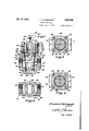
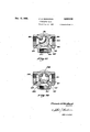
- FIG. 1 is a front view, partly the longitudinal section, of a valve embodying this invention.
- Fig.4 2 is a transverse sectional view taken on the line 2-2 of Fig. 1 looking in the direction indicated by the arrows.
- Fig. 3 is a transverse sectional view taken on the line 3-3 of Fig. 1 looking in the direction indicated by the arrows and showing the valve f member in the full closed position.
- Fig. 4 is a view similar to Fig. 3 but showing the valve member in the full open position.
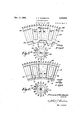
- Fig. 5 is a geometrical development of the contacting surface of the valve -member as shown in Fig. 1.
- Fig. 5a is a correspo member.
- Fig. 6 is a geometrical development of the contacting surface of the valve body as'shown in Fig. 1.
- ding end view of said valve Fig. 6a is a corresponding end view of said valve body.
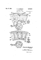
- Figs. '7 and 8 are) geometrical developments similar'to Figs. 5 and 6 respectively, but showing the invention applied to a 2-port 3-way valve. 5
- Figs. 'Ia and 8a are corresponding end views of the valve member and body respectively.
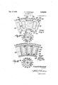
- Figs. 9 and 10 are geometrical developments similar to Figs. 5 and 6 respectively, but showing the invention applied to a'3-port 3-way valve.
- Figs. 9a and 10a are corresponding end views of the valve member and body respectively.
- Fig.- 11 is a transverse sectional view similar to Fig. 2, but showing the invention applied to a 2port 3-way valve of which Figs. 7 and 8 are geometrical developments of the contacting surface of the valve member and body respectively.
- Fig. 12 is a transverse sectional view similar to Fig. 2 but showing the invention applied to a 3-port 3-way valve and of which Figs. 9 and 10 are geometrical developments of the contacting surface of the valve member and body respectively.
- valve structure shown in Figs. 1 to 6 inclusive comprises a body l0 having a passageway I2 for ⁇ uid provided at its terminal ends with threaded portions I4 and I6 by which the valve may be connected to a pipe line. It will be understood that other constructions could be used for this purpose, such as flanges, depending on the size of valve and nature of use.
- the fluid passageway I2 is intersected by a longitudinal tapering valve seat I8 which is closed at its lower end by the cup shaped portion 2li formed on the body IB.
- a frusto-conical valve member 22 having a shoulder 24 at its upper or larger end and a reduced portion forming a valve stem 26 projecting therefrom.
- the valve may be conveniently rotated by the application of a wrench to the stem, the upper end of which is formed with a square section 25 for this purpose.
- the upper end of the body I0 adjacent the valve seat i8 is preferably suitably recessed as at 21 for the reception of anl annular ange 28 depending from a valve retaining plate 30 which 50 may be secured tothe body I0 as by means of the bolts 32.
- the plug retaining plate 30 is provided with a bore 34 which is sufllciently larger than the stem 26 to be spaced therefrom and thus form a stuiiing box.
- the valve member 22 is preferably resiliently held to its seat and for the purpose, and also to prevent leakage along the stem 26, there is provided an annular packing member 36 which is positioned within the stuiiing box between the valve stem and the bore 34.
- the packing 36 is adjusted by means of the packing gland 38 which is movably positioned by the bolts 40 extending from the plug retaining plate 3Il. ⁇
- a thin metallic washer 42 is interposed between the surface of the shoulder 24 and the packing 36.
- valve member is preferably held resiliently to its seat and to permit a longitudinal movement of the valve member 22 a small space 44 is preferably left upon assembly between' the face of theA depending portion 28 and the upper surface of the valve member 22, the depending portion 28 preferably overlapping the shoulder 24 slightly.
- packing 36 is formed of some compressible material, such as asbestos, and is prevented from being extruded from the stuiling box by the overlapping edges of the depending portion 28 and the shoulder 24.
- a port 46 is formed transversely there-through and so proportioned as to register with the passageway I2 in the body I0 when the valve member is in an open position.
- a lug 41 is formed on the end of the stem 26 and extending parallel to the axis of the port 46.
- This invention is more particularly directed to improvements in the lubricating system of valves, such as those of the type described, and to this end the valve member '22 is provided with an internal radial passage 48 adjacent its larger end and communicating with an axial perforation 50 extending therefrom into the stem 26.
- the axial perforation 58 communicates with an enlarged axial bore 52 forming a lubricant reservoir in the stem 26, the bore 52 being threaded for the reception of a lubricant compressor screw 54.
- a check valve member 56 may be positioned in the lower portion of the reservoir 52.
- I'he seating surface I8 is also provided with a plurality of longitudinal groovesfin this instance four grooves'62, y64, 66, 68 being utilized. These longitudinal grooves 62, 64, 66, 68 are spaced at substantially equal intervals around ⁇ the surface I8 and are of such length thatthey do not communicate directly with the circumferential grooves 58 and 68 but terminate short thereof as shown in Fig. 6. The function of these longitudinal grooves however, is to form in conjunction with the circumferential grooves 58 and 60 a complete seal of'lubricant a ound the port 46 and passageway I2 when the v ve is in the open or closed position. These grrves are therefore located adjacent the sides of the passageway I2 asA clearly shown in Fig. 6 with the openings of the passageway I2 spaced between Iopposite pairs of grooves 62, 64 and 66, 68. I
- the connection between the individual longitudinal grooves of the seating surface I8 is pro-A 6 vided by a plurality of non-continuouscircumferential grooves, four such grooves 10, 12, 14, 'I6 being conveniently shown in Fig. 5 as formed in the surface of the valve member 22 beyond theedges of the port 46 and lying between the sides thereof.
- the non-continuous circumferential grooves 10, 12, 14, 'I6 are preferably of such length that each will span any two of the longitudinal grooves 62, 64, 66, 68 when the valve member is-rotated into either the full open or full closed positions and l5 are arranged to overlap the terminal ends of the longitudinal grooves and to lie within the boundary defined between the complete circumferential 4 grooves 58 and 6l).
- connection between the longitudinal 20 grooves and the complete circumferential grooves is provided by short longitudinally projecting grooves 'lllextending from the terminal ends of the non-continuous grooves, "III, '12, 14, 16, those at the upper or larger end of the valve member 25 being projected upwardly and those at the lower or smaller end of the valve member being projected downwardly into overlapping engagement with the complete circumferential grooves 58 and 60.
- the radial passage 48 may communicate at 30 its ends with two opposite short grooves Tl as shown and thus establish communication between the reservoir and the grooves.
- the arrangement of all the various grooves with relation to the seating surface I8 and the contacting surface of valve 85 member 22 is clearly shown in the geometrical development of the surfaces in Figures 5 and 6.
- the connection between the longitudinal and the complete circumferential grooves provided by the non-continuous grooves is clearly shown in Fig. 1. 40
- valve member 22 may be rotated into the closed positionshown in Fig. 1 whereupon a complete seal of lubricant will be formed around the openings of the passageway I2. It 45 will be observed there is also a complete seal of lubricant around the openings of port 46 and that when the valve member is rotated into the full open position shown in Fig. 4 there will again be a complete seal of lubricant around the port 46 and 50 passageway I2. Moreover, although during the time that the valvevmember 22 is being rotated one or more of the longitudinal grooves will be exposed to the fluid in the line, there is a complete disconnection between the longitudinal 55 valve member 22.
- lubricant will con- '65 stantly be conveyed to the seating surface y the remaining two longitudinal grooves in th/s construction, regardless of. the positiony of the valve member 22, as one longitudinal groove is always connected to each non-continuous circumfercn- 70 t tial groove, as will be apparent.
- This invention is not confined to the straightway type of valve shown in Figures 1 to 6 inc lusive, but may be applied with equal facility to the type of valve having a transverse port in the valve member and a plurality of ports in the valve body commonly termed a 2-port 3-way seating surface 92 in contact with which is disvalve.
- a transverse port in the valve member and a plurality of ports in the valve body commonly termed a 2-port 3-way seating surface 92 in contact with which is disvalve.
- FIGs 7, 8 and 11 wherein ⁇ the invention is shown as applied to such a 2-p'ort' 3-way valve.
- This type of valve is usually constructed as shown in Fig. 11, which is a similar view to that in Fig. 2, being a transverse sectional view through a 2- port 3-way valve having structural features similar to that shown in Fig.
- a body 18 having a pair of transverse fluid passageways and 82 and a third iiuid passageway 84 positioned substantially normal thereto.
- the terminal ends of each of these passageways may be threaded as at 86, 88, for connection ⁇ to a pipe line or the ends may be flanged or otherwise constructed to effect such connection.
- the body 18 may be provided with a tapered posed a frusto-conical valve member 94.
- the valve member 94 is provided with a port 96 of angular formationand adapted to register with any two adjacent ports, such as 80 and 84 or 84 and 82.
- the grooving arrangement is slightly modified in this construction to accomplish the features described in connection with Figures 1 to 6 inclusive.
- the seating surface 92 on the body 18 is provided, as shown in ⁇ Fig. 8 with a pair of continuous circumferential grooves 98 and
- 00 are located one between each of the passageways 80, 84, 82, a blank space
- the valve member 94 as shown in the geometrical development Fig. '7, hasa pair of non-continuous circumferential grooves
- 2 arevprovided with longitudinal extending projections H5, and a short longitudinal groove
- Formed in the space immediately between the ,openings of the port 96 is a'pair of short longitudinal grooves
- the sealing effected by the groovlng arrangement shown in Figs. 7, 8 and 11, is similar to that previously described in connection with the straightway type of valve. There will be a complete seal around each passageway in the body 18 and around the port in the valve member 94 whether the valve is in a ful1.open or a full closed position. There is also a disconnection between the longitudinal grooves which are exposed to the'fluid in the (p ssageway during rotation of the valve memb r while two of the longitudinal grooves will/,be connected at all times to the circumferential grooves 98 and
- Figs. 9, 10 and 12 there is shown in Figs. 9, 10 and 12 the application of the lubricant system to a 3-port 3-way valve.
- Fig. 12 is a view similar to that shown in Fig. 2, being a transverse sectional view through a 3port 3-way valve having structural features similar to that shown in Fig. l.
- the body is similar to the body 18 in Fig. 11 and similar reference numerals have been used to designate the similar parts shown in Figs. 10 and 12.
- 'I'he valve member IIB however, which engages the seating surface 92 has a T-shaped port
- 8 may also register with any two adjacent ports 80, 84 or 84, 82 or it may further register with the ports 80 and 82, as in the position shown in Fig. 12.
- 22-I-I24 are disposed in' the blank space or solid portion
- 6 are short longitudinal grooves
- one longitudinal groove is always connected to the continuous circumferential grooves, regardless of the position 0f the valve member, although the longitudinal grooves which are exposed to the fluid in the line during rotation of the valve member are disconnected. There is also a complete seal around the T-shaped port and the passageways in the body when the valve is in the open position or in the closed position.
- lubricating groove arrangement has been specifically defined with relation to the seating surface of the valve body and the engaging surface of the valve member, it will be understood that the position of these grooves could readily be reversed if desired and thatthis invention is not limited to the locationv of specific grooves in either the valve body or the valve member.
- a lubricant inlet in said valve structure means for conducting lubricant to the surface of contact of the valve and seat, including continuous grooves in said surface, and longitudinal grooves in said surface terminating short of said continuous grooves and adapted for vcommunication with said first mentioned grooves in certain positions of the valve member and for non-communication upon movement of the valve member from such positions, but said communication be- -ing constantly maintained by at least one of said longitudinal grooves in all positions of the valve member.
- a valve structure comprising a body having' a valve seat, aplug valve member engaging said seat, a lubricant inlet in said valve structure, means for conducting lubricant to the surface of contact of the valve and seat, including continuous circumferential grooves in said surface, and longitudinal grooves in said surface terminating short of said circumferential grooves and adapted for communication with said first mentioned grooves in certain positions of the valve member and for non-communication upon movement of the valve member from such positions, but said ⁇ communication being constantly maintained by at least one of said longitudinal grooves in all positions of the valve member.
- a valve structure comprising a body having a valve seat, a valve member engaging said seat, a lubricant inlet in said valve structure, means for conducting lubricant to the surface ofcoutact of the valve and seat, including continuous grooves in said surface and longitudinal grooves in said surface terminating short of said continuous grooves and adapted for communication with said rstmentioned groovesto completely frame Athe ports in both the open and closed positions of the valve member and for non-communication upon movement of the valve member from such positions, but said communication being maintained by at least one of said longitudinal grooves in all positions of the valve member.
- a valve structure comprising afbody having a valve seat, a valvel member engaging said seat,
- said body having fluid passageways and said valve member having a port adapted to register with said passageways in the open position of the valve, a lubricant inlet in said valve structure, means for conducting lubricant to the surface of contact of the valve'and seat, including continuous circumferential grooves Iin said surface, longitudinal grooves in said surface terminating short of said circumferential grooves, and means forv establishing communication between the longitudinal and circumferential grooves to completely frame the port in both the open and closed positions of the valve member and for breaking said communication with the longitudinal grooves which may be exposed to the fluid in the passageways upon, movement of the valve member, said communication being constantly maintained with at least one of'said longitudinal grooves in all positions of the valve member.
- a valve structure comprising a body haying a valve seat, a valve member engaging said seat, a lubricant inletin said valve structure, means for conducting lubricant to the surface of contactv of the valveand seat, including continuous circumferential grooves in said surface, longitudinal grooves in said surface terminating short of said circumferential grooves, and non-continuous circumferential grooves in said surface having projections thereon adapted to establish communication between the longitudinal and the continuous circumferential grooves.
- a valve structure comprising a body having a valve seat, a valve member engaging said seat, a lubricant inlet in said valve structure, means for conducting lubricant to the surface of contact of the valve and seat, including continuous circumferential grooves in said surface, longitudinal grooves in said surface terminating short of said circumferential grooves, and non-continuous circumferential grooves in said surface having longitudinally extending projections thereon adapted to .establish communication between the longitudinal and the continuous grooves.
- a valve structure comprising a body having a valve seat, a valve member engaging said seat, said body having a fluid passageway and said circumferential valve member having a port adapted to register with said passageway in the open position of the' valve, a lubricant inlet in said valve structure, means for conducting lubricant to the surface of contact of the valve and seat, including continuous circumferential grooves in said surface, longitudinal grooves in said surface terminating short of said circumferential grooves, and noncontinuous circumferential 'grooves in said surface having projections thereon adapted to establish communication between the longitudinal and the lous circumferential grooves in said surface, longitudinal grooves in said surface terminating short of said circumferential grooves, and noncontinuous circumferential grooves in said surface having projections thereon adapted to establish communication between thel longitudinal and the continuous circumferential grooves to completely frame the portin both the open and closed positions of the valve member, and for breaking said communication with the longitudinal grooves which may be exposed to the fluid in the passageway upon movement of the valve member
- a valve structure comprising a body having a valve seat provided with ⁇ passageways for fluid, a valve member engaging said seat and provided with a port adapted to register with said passage.. ways when the valve member is in open position, a lubricant in said valve structure, means for conductingv lubricant to the surface of contact of the valve and seat, including continuous circumferin said surface located on each side of each pas- ,L
- a valve structure comprising a body having avalve seat provided with a pair of aligned transverse fluid passageways, a Valve member engaging said seat andprovidedlwith a transverse port adapted to register with said passageways in the open position of the yalve, av lubricantinlet in said valve structure, means for conducting lubricant to the surface of contact of the valve and seat, including continuous circumferential grooves i in said surface on each side of the port beyond x the ends thereof, longitudinal grooves in said surface located on each side of each passageway and terminating short.
- a valve structure comprising a body having a valve seat provided with apair of aligned transverse uid passageways and a third fluid passageway substantially normal thereto, a valve member engaging said seat and provided with a transverse port adapted to register with two adjacent fluid passageways in the open position of the valve, a lubricant inlet in said valve structure, means for conducting lubricant to the surface of contact of the valve and seat, including continuous circumferential grooves in said surface on each side of the port beyond the ends thereof, longitudinal grooves in said surface located on each side of each passageway and terminating short of said circumferential grooves,A and means 5 for ⁇ establishing communication between the longitudinal and circumferential grooves to completely frame the port in both the open and closed positions of the valve member and for breaking said communication with the longitudinal grooves which may be exposed to the fluid in the passage- Ways upon movement of the valve member, said communication being constantly maintained with at least one longitudinal groove in all positions ef the valve member.
- a valve structure comprising a'body having a valve seat provided with a pair of aligned transverse fluid passageways and a third fluid passageway substantially normal thereto, a valve memberl engaging said seat and provided with a T-shaped port adapted to register with s'aid fluid passageways in the open position of the valve, a lubricant inlet in said valve structure, means for conducting lubricant to the surface of contact of the valve and seat, including continuous circumferential grooves in said surface on each side of the port beyond the ends thereof, longitudinal grooves in said surface located on each side of each passageway and terminating short of said circumferential grooves, and means for establishing commmunication between the longitudinal and circumferential grooves to completely frame the port in both the open and closed positions of the valve member and for breaking said communication with the longitudinal grooves which may be exposed to the fluid in the passagewaysl upon movement of the valve member, said communication being constantly maintained with at least one longitudinal groove in all positions of the valve member.
Landscapes
- Engineering & Computer Science (AREA)
- General Engineering & Computer Science (AREA)
- Mechanical Engineering (AREA)
- Sliding Valves (AREA)
Description
Dec. .17, 1935. F, H, MOREHEAD 2,024,945
LUBRICATED VALVE Filed July 13, 1932 5 Sheets-Sheet l y 4725 Je V48 Je 3.346 ZZ l0 .K2
Jrwnzffizmzuaa INVFJV TOR.
l/d ATTORNEY.
Dec. 17, 1935. F. H. MORI-:HEAD
LUBR I C ATED IVALVE 5 Sheets-Sheet 2 NVENTOR.
Filed July 13, 1932 H0 ATTORNEY.
Dec. 17, 1935.` F; MORHEAD 2,024,945
LUBRICATED VALVE Filed July 13, 1932 5 Sheets-Sheet 5 1N VEN TOR.
H15 A TTORNEY.
De. 17, 1935. H, MOREHEAD 2,024,945
' LUBRICATED VALVE Filed July 13, i932 s sheets-sheet 4 7 Fmcjlore/Iead IN VEN TOR.
HH A TTORNE Y.
Dec. 17', 1935. F MOREHEAD y 2,024,945
Y LUBRIQATED VALVE Filed July 13, 193.2l s sheets-sheet 5 Il', 'M
INVENTOR.
/l/J' ATTORNEY.
Patented Dec. 17, 1935 UNITED STATES PATENT OFFICE moreland County, Pa.,
assignor to Walworth Patents Inc., Boston, Mass., a corporation of Massachusetts Application July 13, 1932, Serial No. 622,196
12 Claims.
This invention relates to lubricated valves and' more particularly to improved means of supplying lubricant to the surface of contact of the valve member and its seat.
An object of this invention is to distribute lubricant adequately and continuously to the seating surface of lubricated valves.
Another object of this invention is to maintain a flow of lubricant between the source of supply and the seating surface most distant therefrom regardless of whether the valve is open or closed or in any position therebetween.
Another object of this invention is to frame the passageways of a valve when in certain positions with a seal of lubricant to prevent leakage.
Another object of this invention is to prevent the main body o`f lubricant contained in the valve from being exposed to the fluid from the pipe line during movement of the valve.
Another object of this invention is to prevent the fluid flowing through the valve from entering the lubricating system in any position of the valve member.
Another object of this invention is to so arrange the lubricating system that it will be equally eiective on multi-port valves as on the ordinary straight-way type.
Another object of the invention is to prevent the exposure of the main body of the lubricant in the valve tothe fluid from the pipe line without limiting the degree of rotation of the valve by stops or the like.
Other objects and advantages will become apparent from the following description taken in'l connection with the accompanying drawings whereinz- Fig. 1 is a front view, partly the longitudinal section, of a valve embodying this invention.
Fig.4 2 is a transverse sectional view taken on the line 2-2 of Fig. 1 looking in the direction indicated by the arrows.
Fig. 3 is a transverse sectional view taken on the line 3-3 of Fig. 1 looking in the direction indicated by the arrows and showing the valve f member in the full closed position.
Fig. 4 is a view similar to Fig. 3 but showing the valve member in the full open position.
Fig. 5 is a geometrical development of the contacting surface of the valve -member as shown in Fig. 1.
Fig. 5a is a correspo member.
Fig. 6 is a geometrical development of the contacting surface of the valve body as'shown in Fig. 1.
ding end view of said valve Fig. 6a is a corresponding end view of said valve body.
Figs. '7 and 8 are) geometrical developments similar'to Figs. 5 and 6 respectively, but showing the invention applied to a 2-port 3-way valve. 5
Figs. 'Ia and 8a are corresponding end views of the valve member and body respectively.
Figs. 9 and 10 are geometrical developments similar to Figs. 5 and 6 respectively, but showing the invention applied to a'3-port 3-way valve.
Figs. 9a and 10a are corresponding end views of the valve member and body respectively.
Fig.- 11 is a transverse sectional view similar to Fig. 2, but showing the invention applied to a 2port 3-way valve of which Figs. 7 and 8 are geometrical developments of the contacting surface of the valve member and body respectively.
Fig. 12 is a transverse sectional view similar to Fig. 2 but showing the invention applied to a 3-port 3-way valve and of which Figs. 9 and 10 are geometrical developments of the contacting surface of the valve member and body respectively.
Referring more particularly to the drawings wherein similar characters of reference designate corresponding parts throughout the several views the valve structure shown in Figs. 1 to 6 inclusive comprises a body l0 having a passageway I2 for` uid provided at its terminal ends with threaded portions I4 and I6 by which the valve may be connected to a pipe line. It will be understood that other constructions could be used for this purpose, such as flanges, depending on the size of valve and nature of use.
The fluid passageway I2 is intersected by a longitudinal tapering valve seat I8 which is closed at its lower end by the cup shaped portion 2li formed on the body IB. Contacting with the valve seat I8 is a frusto-conical valve member 22 having a shoulder 24 at its upper or larger end and a reduced portion forming a valve stem 26 projecting therefrom. The valve may be conveniently rotated by the application of a wrench to the stem, the upper end of which is formed with a square section 25 for this purpose.
The upper end of the body I0 adjacent the valve seat i8 is preferably suitably recessed as at 21 for the reception of anl annular ange 28 depending from a valve retaining plate 30 which 50 may be secured tothe body I0 as by means of the bolts 32. The plug retaining plate 30 is provided with a bore 34 which is sufllciently larger than the stem 26 to be spaced therefrom and thus form a stuiiing box.
The valve member 22 is preferably resiliently held to its seat and for the purpose, and also to prevent leakage along the stem 26, there is provided an annular packing member 36 which is positioned within the stuiiing box between the valve stem and the bore 34. The packing 36 is adjusted by means of the packing gland 38 which is movably positioned by the bolts 40 extending from the plug retaining plate 3Il.` In order that the valve member 22 may be freely rotated without undue friction from the packing a thin metallic washer 42 is interposed between the surface of the shoulder 24 and the packing 36.
As previously stated, the valve member is preferably held resiliently to its seat and to permit a longitudinal movement of the valve member 22 a small space 44 is preferably left upon assembly between' the face of theA depending portion 28 and the upper surface of the valve member 22, the depending portion 28 preferably overlapping the shoulder 24 slightly. It will be understood that the packing 36 is formed of some compressible material, such as asbestos, and is prevented from being extruded from the stuiling box by the overlapping edges of the depending portion 28 and the shoulder 24. To provide a passage for fluid through the valve member 22 a port 46 is formed transversely there-through and so proportioned as to register with the passageway I2 in the body I0 when the valve member is in an open position. As some means is necessary to indicate the relative positions of the port 46 andpassageway I2, a lug 41 is formed on the end of the stem 26 and extending parallel to the axis of the port 46.
This invention is more particularly directed to improvements in the lubricating system of valves, such as those of the type described, and to this end the valve member '22 is provided with an internal radial passage 48 adjacent its larger end and communicating with an axial perforation 50 extending therefrom into the stem 26. The axial perforation 58 communicates with an enlarged axial bore 52 forming a lubricant reservoir in the stem 26, the bore 52 being threaded for the reception of a lubricant compressor screw 54. In order to prevent a reux of lubricant from the valve when the compressor screw 54 is `re moved, a check valve member 56 may be positioned in the lower portion of the reservoir 52.
The distribution of lubricant to the surface of contact of the valve member and its seat is accomplished by a novel arrangement of lubricant grooves formed in the seating surface and communicating with the radial passage 48. In the embodiment shown in Figures 1 to 6 inclusive the invention has been applied to a valve of the ordinary straightway type. Accordingly, a pair of continuous circumferential grooves 58 and 60 are formed in the seating surface I8 beyond the ends of the passageway I2.
I'he seating surface I8 is also provided with a plurality of longitudinal groovesfin this instance four grooves'62, y64, 66, 68 being utilized. These longitudinal grooves 62, 64, 66, 68 are spaced at substantially equal intervals around `the surface I8 and are of such length thatthey do not communicate directly with the circumferential grooves 58 and 68 but terminate short thereof as shown in Fig. 6. The function of these longitudinal grooves however, is to form in conjunction with the circumferential grooves 58 and 60 a complete seal of'lubricant a ound the port 46 and passageway I2 when the v ve is in the open or closed position. These grrves are therefore located adjacent the sides of the passageway I2 asA clearly shown in Fig. 6 with the openings of the passageway I2 spaced between Iopposite pairs of grooves 62, 64 and 66, 68. I
The connection between the individual longitudinal grooves of the seating surface I8 is pro-A 6 vided by a plurality of non-continuouscircumferential grooves, four such grooves 10, 12, 14, 'I6 being conveniently shown in Fig. 5 as formed in the surface of the valve member 22 beyond theedges of the port 46 and lying between the sides thereof. 10 The non-continuous circumferential grooves 10, 12, 14, 'I6 are preferably of such length that each will span any two of the longitudinal grooves 62, 64, 66, 68 when the valve member is-rotated into either the full open or full closed positions and l5 are arranged to overlap the terminal ends of the longitudinal grooves and to lie within the boundary defined between the complete circumferential 4 grooves 58 and 6l).
The connection between the longitudinal 20 grooves and the complete circumferential grooves is provided by short longitudinally projecting grooves 'lllextending from the terminal ends of the non-continuous grooves, "III, '12, 14, 16, those at the upper or larger end of the valve member 25 being projected upwardly and those at the lower or smaller end of the valve member being projected downwardly into overlapping engagement with the complete circumferential grooves 58 and 60. The radial passage 48 may communicate at 30 its ends with two opposite short grooves Tl as shown and thus establish communication between the reservoir and the grooves. The arrangement of all the various grooves with relation to the seating surface I8 and the contacting surface of valve 85 member 22 is clearly shown in the geometrical development of the surfaces in Figures 5 and 6. The connection between the longitudinal and the complete circumferential grooves provided by the non-continuous grooves is clearly shown in Fig. 1. 40
In the operation of device shown in Figures 1 to 6 inclusive the valve member 22 may be rotated into the closed positionshown in Fig. 1 whereupon a complete seal of lubricant will be formed around the openings of the passageway I2. It 45 will be observed there is also a complete seal of lubricant around the openings of port 46 and that when the valve member is rotated into the full open position shown in Fig. 4 there will again be a complete seal of lubricant around the port 46 and 50 passageway I2. Moreover, although during the time that the valvevmember 22 is being rotated one or more of the longitudinal grooves will be exposed to the fluid in the line, there is a complete disconnection between the longitudinal 55 valve member 22. However, lubricant will con- '65 stantly be conveyed to the seating surface y the remaining two longitudinal grooves in th/s construction, regardless of. the positiony of the valve member 22, as one longitudinal groove is always connected to each non-continuous circumfercn- 70 t tial groove, as will be apparent.
This invention is not confined to the straightway type of valve shown in Figures 1 to 6 inc lusive, but may be applied with equal facility to the type of valve having a transverse port in the valve member and a plurality of ports in the valve body commonly termed a 2-port 3-way seating surface 92 in contact with which is disvalve. As an illustration, reference may be made to Figures 7, 8 and 11, wherein` the invention is shown as applied to such a 2-p'ort' 3-way valve. This type of valve is usually constructed as shown in Fig. 11, which is a similar view to that in Fig. 2, being a transverse sectional view through a 2- port 3-way valve having structural features similar to that shown in Fig. 1, but being'provided with a body 18 having a pair of transverse fluid passageways and 82 and a third iiuid passageway 84 positioned substantially normal thereto. The terminal ends of each of these passageways may be threaded as at 86, 88, for connection `to a pipe line or the ends may be flanged or otherwise constructed to effect such connection. The body 18 may be provided with a tapered posed a frusto-conical valve member 94. In this instance, the valve member 94 is provided with a port 96 of angular formationand adapted to register with any two adjacent ports, such as 80 and 84 or 84 and 82. The grooving arrangement is slightly modified in this construction to accomplish the features described in connection with Figures 1 to 6 inclusive.
In this instance, the seating surface 92 on the body 18 is provided, as shown in` Fig. 8 with a pair of continuous circumferential grooves 98 and |00 disposed above and below the margins of the passageways 80, 82 and 84. A plurality of longitudinal grooves |02, |04, |08, |08 terminating short of the continuous circumferential grooves 98 and |00 are located one between each of the passageways 80, 84, 82, a blank space |09 being present between the grooves |08 and |02, as clearly shown in the geometrical development in Fig. 8.
, The valve member 94, as shown in the geometrical development Fig. '7, hasa pair of non-continuous circumferential grooves ||0, l2 located above and below the margins of the ports 96 but being formed in the blank space ||3, between these ports.
The terminal ends of the non-continuous grooves ||0, ||2 arevprovided with longitudinal extending projections H5, and a short longitudinal groove ||1 is also formed in the interl mediate portion of these non-continuous grooves. Formed in the space immediately between the ,openings of the port 96 is a'pair of short longitudinal grooves ||4, IIS, which are of similar size to the projections ||5 on the ends of the non-continuous grooves |00, I|2. It will be apparent however, that complete sealing 'of the ports and passageway may be effected without the grooves although these short grooves ||1 arranged asshown, shorten the path of lubricant in certain positions of the valve member.
The sealing effected by the groovlng arrangement shown in Figs. 7, 8 and 11, is similar to that previously described in connection with the straightway type of valve. There will be a complete seal around each passageway in the body 18 and around the port in the valve member 94 whether the valve is in a ful1.open or a full closed position. There is also a disconnection between the longitudinal grooves which are exposed to the'fluid in the (p ssageway during rotation of the valve memb r while two of the longitudinal grooves will/,be connected at all times to the circumferential grooves 98 and |00. These circumferential grooves 98 and |00 are thus connected together at all times and continuously receive lubricant for distribution to any part of the seating surface.
As a further alternative form of the invention, there is shown in Figs. 9, 10 and 12 the application of the lubricant system to a 3-port 3-way valve. Fig. 12 is a view similar to that shown in Fig. 2, being a transverse sectional view through a 3port 3-way valve having structural features similar to that shown in Fig. l. In this embodiment however, the body is similar to the body 18 in Fig. 11 and similar reference numerals have been used to designate the similar parts shown in Figs. 10 and 12. 'I'he valve member IIB however, which engages the seating surface 92 has a T-shaped port ||8 adapted to register with all 3-ports, 80, 82 and 84. This T-shaped port ||8 may also register with any two adjacent ports 80, 84 or 84, 82 or it may further register with the ports 80 and 82, as in the position shown in Fig. 12.
As shown in the geometrical development of the valve member IIS in Fig. 9 a pair of noncontinuous circumferential grooves |22-I-I24 are disposed in' the blank space or solid portion |20 between the ends of the port ||8 and provided with projecting terminal end portions |23,-for connection with the continuous circumferential grooves 98 and |00 of the seating surface 92 Fig. ,10. Located between vthe openings of the T-shaped port ||8 in the valve member ||6 are short longitudinal grooves |26|28|30|32 which will connect the longitudinal grooves in the seating surface 92 with the continuous circumferential grooves 98' and |00 according to the position of the valve member. In this embodiment one longitudinal groove is always connected to the continuous circumferential grooves, regardless of the position 0f the valve member, although the longitudinal grooves which are exposed to the fluid in the line during rotation of the valve member are disconnected. There is also a complete seal around the T-shaped port and the passageways in the body when the valve is in the open position or in the closed position.
In all the embodiments shown it will be apparent that as the longitudinal grooves become exposed during rotation of the valve member to fluid in the line they are automatically cut off from communication with the lubricant reserr This feature renders the use of stops or voir. other rotation limiting devices unnecessary, a1- though stops may be desirable particularly on the multi-port valves. Some position indicating means is, of course, necessary on these valves and an exemplary embodiment 41 is shown in Fig. 1.
Although the lubricating groove arrangement has been specifically defined with relation to the seating surface of the valve body and the engaging surface of the valve member, it will be understood that the position of these grooves could readily be reversed if desired and thatthis invention is not limited to the locationv of specific grooves in either the valve body or the valve member. f
From the foregoing description, it willbe apparent that simple means have been provided whereby a complete framingof the port and pas-1 70 source of supply to the seating surface most distant therefrom, regardless of whether the valve V is in the open or closed or any intermediate a valve seat, a valve member engaging said seat,
a lubricant inlet in said valve structure, means for conducting lubricant to the surface of contact of the valve and seat, including continuous grooves in said surface, and longitudinal grooves in said surface terminating short of said continuous grooves and adapted for vcommunication with said first mentioned grooves in certain positions of the valve member and for non-communication upon movement of the valve member from such positions, but said communication be- -ing constantly maintained by at least one of said longitudinal grooves in all positions of the valve member.
2. A valve structure comprising a body having' a valve seat, aplug valve member engaging said seat, a lubricant inlet in said valve structure, means for conducting lubricant to the surface of contact of the valve and seat, including continuous circumferential grooves in said surface, and longitudinal grooves in said surface terminating short of said circumferential grooves and adapted for communication with said first mentioned grooves in certain positions of the valve member and for non-communication upon movement of the valve member from such positions, but said `communication being constantly maintained by at least one of said longitudinal grooves in all positions of the valve member.
3. A valve structure comprising a body having a valve seat, a valve member engaging said seat, a lubricant inlet in said valve structure, means for conducting lubricant to the surface ofcoutact of the valve and seat, including continuous grooves in said surface and longitudinal grooves in said surface terminating short of said continuous grooves and adapted for communication with said rstmentioned groovesto completely frame Athe ports in both the open and closed positions of the valve member and for non-communication upon movement of the valve member from such positions, but said communication being maintained by at least one of said longitudinal grooves in all positions of the valve member.
4. A valve structure comprising afbody having a valve seat, a valvel member engaging said seat,
said body having fluid passageways and said valve member having a port adapted to register with said passageways in the open position of the valve, a lubricant inlet in said valve structure, means for conducting lubricant to the surface of contact of the valve'and seat, including continuous circumferential grooves Iin said surface, longitudinal grooves in said surface terminating short of said circumferential grooves, and means forv establishing communication between the longitudinal and circumferential grooves to completely frame the port in both the open and closed positions of the valve member and for breaking said communication with the longitudinal grooves which may be exposed to the fluid in the passageways upon, movement of the valve member, said communication being constantly maintained with at least one of'said longitudinal grooves in all positions of the valve member.
5. A valve structure comprising a body haying a valve seat, a valve member engaging said seat, a lubricant inletin said valve structure, means for conducting lubricant to the surface of contactv of the valveand seat, including continuous circumferential grooves in said surface, longitudinal grooves in said surface terminating short of said circumferential grooves, and non-continuous circumferential grooves in said surface having projections thereon adapted to establish communication between the longitudinal and the continuous circumferential grooves.
6. A valve structure comprising a body having a valve seat, a valve member engaging said seat, a lubricant inlet in said valve structure, means for conducting lubricant to the surface of contact of the valve and seat, including continuous circumferential grooves in said surface, longitudinal grooves in said surface terminating short of said circumferential grooves, and non-continuous circumferential grooves in said surface having longitudinally extending projections thereon adapted to .establish communication between the longitudinal and the continuous grooves.`
7. A valve structure comprising a body having a valve seat, a valve member engaging said seat, said body having a fluid passageway and said circumferential valve member having a port adapted to register with said passageway in the open position of the' valve, a lubricant inlet in said valve structure, means for conducting lubricant to the surface of contact of the valve and seat, including continuous circumferential grooves in said surface, longitudinal grooves in said surface terminating short of said circumferential grooves, and noncontinuous circumferential 'grooves in said surface having projections thereon adapted to establish communication between the longitudinal and the lous circumferential grooves in said surface, longitudinal grooves in said surface terminating short of said circumferential grooves, and noncontinuous circumferential grooves in said surface having projections thereon adapted to establish communication between thel longitudinal and the continuous circumferential grooves to completely frame the portin both the open and closed positions of the valve member, and for breaking said communication with the longitudinal grooves which may be exposed to the fluid in the passageway upon movement of the valve member, said communication being constantly maintained with at least one longitudinal groove in all positions of the valve member.
'9. A valve structure comprising a body having a valve seat provided with `passageways for fluid, a valve member engaging said seat and provided with a port adapted to register with said passage.. ways when the valve member is in open position, a lubricant in said valve structure, means for conductingv lubricant to the surface of contact of the valve and seat, including continuous circumferin said surface located on each side of each pas- ,L
sageway and terminating short of said circumferential grooves, and means for establishing communication between the longitudinal and circumferential grooves to completely frame the port in both the open and closedpositons of the valve member and for breaking said communication with the longitudinal grooves which may be exposed to the fluid in the passageways upon move- 'ment of the valve member, said communication being constantly maintained with at least one of said longitudinal grooves in all positions of the valve member.
10. A valve structure comprising a body having avalve seat provided with a pair of aligned transverse fluid passageways, a Valve member engaging said seat andprovidedlwith a transverse port adapted to register with said passageways in the open position of the yalve, av lubricantinlet in said valve structure, means for conducting lubricant to the surface of contact of the valve and seat, including continuous circumferential grooves i in said surface on each side of the port beyond x the ends thereof, longitudinal grooves in said surface located on each side of each passageway and terminating short. of said circumferential grooves, and means for establishing communication between the longitudinal and circumferential grooves to' completely frame the port in both the open and closed positions of the valve member and for breaking said communication'with Ythe longitudinal grooves which may be exposed to the iiuid in the passageways upon movement cf the valve member, said communication being constantly maintained with at least one longitudinal groove in all positions of the valve member.
11. A valve structure comprising a body having a valve seat provided with apair of aligned transverse uid passageways and a third fluid passageway substantially normal thereto, a valve member engaging said seat and provided with a transverse port adapted to register with two adjacent fluid passageways in the open position of the valve, a lubricant inlet in said valve structure, means for conducting lubricant to the surface of contact of the valve and seat, including continuous circumferential grooves in said surface on each side of the port beyond the ends thereof, longitudinal grooves in said surface located on each side of each passageway and terminating short of said circumferential grooves,A and means 5 for` establishing communication between the longitudinal and circumferential grooves to completely frame the port in both the open and closed positions of the valve member and for breaking said communication with the longitudinal grooves which may be exposed to the fluid in the passage- Ways upon movement of the valve member, said communication being constantly maintained with at least one longitudinal groove in all positions ef the valve member. l5 12. A valve structure comprising a'body having a valve seat provided with a pair of aligned transverse fluid passageways and a third fluid passageway substantially normal thereto, a valve memberl engaging said seat and provided with a T-shaped port adapted to register with s'aid fluid passageways in the open position of the valve, a lubricant inlet in said valve structure, means for conducting lubricant to the surface of contact of the valve and seat, including continuous circumferential grooves in said surface on each side of the port beyond the ends thereof, longitudinal grooves in said surface located on each side of each passageway and terminating short of said circumferential grooves, and means for establishing commmunication between the longitudinal and circumferential grooves to completely frame the port in both the open and closed positions of the valve member and for breaking said communication with the longitudinal grooves which may be exposed to the fluid in the passagewaysl upon movement of the valve member, said communication being constantly maintained with at least one longitudinal groove in all positions of the valve member.
, FRENCH H. MOREHEAD.
Priority Applications (1)
| Application Number | Priority Date | Filing Date | Title |
|---|---|---|---|
| US62219632 US2024945A (en) | 1932-07-13 | 1932-07-13 | Lubricated valve |
Applications Claiming Priority (1)
| Application Number | Priority Date | Filing Date | Title |
|---|---|---|---|
| US62219632 US2024945A (en) | 1932-07-13 | 1932-07-13 | Lubricated valve |
Publications (1)
| Publication Number | Publication Date |
|---|---|
| US2024945A true US2024945A (en) | 1935-12-17 |
Family
ID=24493263
Family Applications (1)
| Application Number | Title | Priority Date | Filing Date |
|---|---|---|---|
| US62219632 Expired - Lifetime US2024945A (en) | 1932-07-13 | 1932-07-13 | Lubricated valve |
Country Status (1)
| Country | Link |
|---|---|
| US (1) | US2024945A (en) |
Cited By (1)
| Publication number | Priority date | Publication date | Assignee | Title |
|---|---|---|---|---|
| US2931380A (en) * | 1957-02-08 | 1960-04-05 | Mueller Co | Lubricated rotary plug valve |
-
1932
- 1932-07-13 US US62219632 patent/US2024945A/en not_active Expired - Lifetime
Cited By (1)
| Publication number | Priority date | Publication date | Assignee | Title |
|---|---|---|---|---|
| US2931380A (en) * | 1957-02-08 | 1960-04-05 | Mueller Co | Lubricated rotary plug valve |
Similar Documents
| Publication | Publication Date | Title |
|---|---|---|
| US2121936A (en) | Combination excess flow and check valve | |
| US3504885A (en) | Seat and seal assembly for valves | |
| US2201895A (en) | Rotary plug valve with spherical plugs | |
| US2900995A (en) | Jacketed valve | |
| US2032623A (en) | Valve | |
| US3538938A (en) | Automatic sealant sealed valves | |
| US2269887A (en) | Lubricated valve | |
| US4222406A (en) | Wedge-type gate valve | |
| US2024945A (en) | Lubricated valve | |
| US2146336A (en) | Derivation clip serving for junction of a cock to a water conduit | |
| US2999510A (en) | Automatic lubricant-sealed plug valve | |
| US2169810A (en) | Lubricated valve | |
| US2065726A (en) | Plug valve | |
| US2608374A (en) | Valve | |
| US2482873A (en) | Multiple valve and packing therefor | |
| US2605078A (en) | Automatic sealing gate valve | |
| US2845080A (en) | Automatic or manual hot water vent valve assembly | |
| US2124359A (en) | Stopcock | |
| US2011113A (en) | Lubricated plug valve | |
| US2119766A (en) | Valve | |
| US2216150A (en) | Lubricated valve | |
| US1634722A (en) | Valve | |
| US1365116A (en) | Plug-cock | |
| US2855956A (en) | Gas valves | |
| USRE17375E (en) | Vaivb |