US2024936A - Flusher type spray nozzle - Google Patents
Flusher type spray nozzle Download PDFInfo
- Publication number
- US2024936A US2024936A US652319A US65231933A US2024936A US 2024936 A US2024936 A US 2024936A US 652319 A US652319 A US 652319A US 65231933 A US65231933 A US 65231933A US 2024936 A US2024936 A US 2024936A
- Authority
- US
- United States
- Prior art keywords
- nozzle
- sections
- nozzle member
- neck
- body member
- Prior art date
- Legal status (The legal status is an assumption and is not a legal conclusion. Google has not performed a legal analysis and makes no representation as to the accuracy of the status listed.)
- Expired - Lifetime
Links
Images
Classifications
-
- B—PERFORMING OPERATIONS; TRANSPORTING
- B05—SPRAYING OR ATOMISING IN GENERAL; APPLYING FLUENT MATERIALS TO SURFACES, IN GENERAL
- B05B—SPRAYING APPARATUS; ATOMISING APPARATUS; NOZZLES
- B05B1/00—Nozzles, spray heads or other outlets, with or without auxiliary devices such as valves, heating means
- B05B1/02—Nozzles, spray heads or other outlets, with or without auxiliary devices such as valves, heating means designed to produce a jet, spray, or other discharge of particular shape or nature, e.g. in single drops, or having an outlet of particular shape
- B05B1/04—Nozzles, spray heads or other outlets, with or without auxiliary devices such as valves, heating means designed to produce a jet, spray, or other discharge of particular shape or nature, e.g. in single drops, or having an outlet of particular shape in flat form, e.g. fan-like, sheet-like
- B05B1/042—Outlets having two planes of symmetry perpendicular to each other, one of them defining the plane of the jet
-
- B—PERFORMING OPERATIONS; TRANSPORTING
- B05—SPRAYING OR ATOMISING IN GENERAL; APPLYING FLUENT MATERIALS TO SURFACES, IN GENERAL
- B05B—SPRAYING APPARATUS; ATOMISING APPARATUS; NOZZLES
- B05B15/00—Details of spraying plant or spraying apparatus not otherwise provided for; Accessories
- B05B15/50—Arrangements for cleaning; Arrangements for preventing deposits, drying-out or blockage; Arrangements for detecting improper discharge caused by the presence of foreign matter
- B05B15/52—Arrangements for cleaning; Arrangements for preventing deposits, drying-out or blockage; Arrangements for detecting improper discharge caused by the presence of foreign matter for removal of clogging particles
- B05B15/525—Arrangements for cleaning; Arrangements for preventing deposits, drying-out or blockage; Arrangements for detecting improper discharge caused by the presence of foreign matter for removal of clogging particles by increasing the cross section of the discharge openings
Definitions
- My present invention relates to spray nozzles, and has for its object the provision of an extremely simple and highly efficient spray nozzle of the flusher type.
- the invention is intended for general use in vspraying all kinds of fluids, it is especially Well adapted for spraying fluids containing solids or other foreign matter that would tend to clog the discharge orifice and thus reduce the eciency of the nozzle.
- the invention is also especially'well adapted for spraying oil on coal to allay dust, and in which use, it will break up the oil stream into a line spray at low uid pressure.
- the invention consists of the novel devices and combinations of devices hereinafter described and defined in the claims.
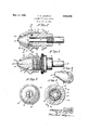
- Fig. 1 is a View partly in side elevation and partly in longitudinal central section
- Fig. 2 is a view principally in section taken on the line 2-2 of Fig. 1;
- Fig. ⁇ 3 is a front elevation of the improved nozzle
- Fig. 4 is a transverse section taken on the line 4-4 of Fig. 2;
- Fig. 5 is-a perspective view of one of the sections of the nozzle member.
- the improved spray nozzle includes an annular body member l, the front end portion of which is reduced in diameter to form an annular neck 8 that is axially aligned therewith.
- a passage 9 extends axially through the body member 1 and the neck 8.
- Formed in the neck 8 is an external annular seat I0 that is channel-shaped in crosssection. Extending transversely through the seat I0 is a key II in the form of a pin, the end portions of which are fitted inl a bore in the body member 'I and thereby rigidly hold said key in place.
- the improved spray nozzle is secured to the delivery end of a fixed pipe I2 that leads from a suitable source of fluid supply, not shown.
- This pipe I2 extends into the passage 9, from the inner end of the body member l, and is secured by screw-threads to said member.
- the improved spray nozzle further includes a sectional nozzle member I3 in the form of a cylindrical shell having a conical outer end portion I4.
- the two sections of the nozzle member I3 are semi-cylindrical in cross-section and the neck 8 extends into the shell from the inner end thereof. It will be ⁇ noted that there is clearance between the neck 8 and internal Walls of the nozzle member I3 to permit the edges of the sides of the sections of said member to contact and to 5 be tightly pressed together, as will hereinafter appear.
- annular ange I5 Formed with the inner ends of the sections of the nozzle member I3 is an annular ange I5 that projects into the seat I0 and detachably interlocks the nozzle member I3 with the neck 8, and thereby holds said member against removal from the neck 8 and hence the body member 1, except by radial movements. It Will be noted that the free edge of the flange I5 is spaced from the bottom of the seat Il) so as not to interfere with the pressing of the sections of the nozzle member I3 together. It will also be noted that there is clearance between the sides of the seat I0 and the sides of the flange I5 to permit slight axial movement of the nozzle member I 3 with respect to the body member l.
- a pair of notches I6 are formed one in one of the ends of each section of the flange I5 and diametrically arranged to receive the key II and thereby prevent rotation of the nozzle member I3 with respect to the body member l. In assembling the sections of the nozzle I3 around the neck 8, either notch I may be brought into registration with the key II.
- a discharge orifice I1 in the form of a narrow slot.
- This orifice Il is formed entirely in one of the sections ofthe nozzle member I3 and Will produce a Very fine spray. If a Widerêt I1 is required, for a heavy spray, the same may be formed in both of the sections of the nozzle member I3.
- the two sections of the nozzle member I3 are held in assembled relation with the fla-nge I5 in the seat I0 by a clamping member or sleeve I8, the base or inner end portion of which surrounds the outer end portion of the body member I and has screw-threaded engagement therewith for axial adjustment thereon.
- the outer end portion of the clamping sleeve I8 is in the form of a truncated cone I9 that cages the nozzle member I3.
- the opening in the outer end portion'of the clamping sleeve I8 is indicated by the numeral 20.
- the apex of the nozzle member I3, in which the tone I1 is formed, normally projects through the opening 20 and at which time saidtechnisch is entirely outwardly of said member.
- the internal surface of the conical member I9 normally engages the external surface of the conical 55 member I4 and which surfaces have substantially the same pitch.
- the object of the key Ii is to prevent turning movement; of the nozzle member I3 about its axis with respect to the body member 'i during the screwing and unscrewing of the clamping sleeve I8 and the flushing of the nozzle.
- clamping sleeve I8 is again screwed onto the body member 'I which auto- Y matically clamps the sections of the nozzle member I3 together.
- the two sections of the nozzle member I3 are duplicates and each thereof is pressed or stamped, preferably from sheet metal, and the internal edges thereof at the Kau Il are relatively sharp and divide the oil at the spray. Also the narrow orifice I'I and the relatively thick walls thereof will assist in cutting the oil and producing a finely divided spray.
- a body member having a neck and a fluid passage extending through said member and neck, said neck having an annular seat, a nozzle member comprising a shell made up of vindividual semi-cylindrical sections surrounding the neck and having on their inner ends internal flanges extending into the seat for holding the nozzle memberV against axial movement away from the body member but permitting its sections to separate radially, said nozzle member having a conical outer end portion and a discharge orifice in said end, and a clamping sleeve adjustable on the body member, surrounding the nozzle member, normally engaging the conical end thereof and holding the sections of the nozzle member pressed together, said clamping sleeve being operative to release said sections by an axial movement therefrom and permit the same to separate radially.
Description
Dec. 17, 1935. T. A. LoUGr-LIN t 2,024,936
FLUSHER TYPE SPRAY NOZZLE Filed Jan, 18, 1953 Patented Dec. 17, 1935 UNITED STATES PATENT OFFICE 2 Claims.
My present invention relates to spray nozzles, and has for its object the provision of an extremely simple and highly efficient spray nozzle of the flusher type.
While the invention is intended for general use in vspraying all kinds of fluids, it is especially Well adapted for spraying fluids containing solids or other foreign matter that would tend to clog the discharge orifice and thus reduce the eciency of the nozzle.
The invention is also especially'well adapted for spraying oil on coal to allay dust, and in which use, it will break up the oil stream into a line spray at low uid pressure.
To the above end, generally stated, the invention consists of the novel devices and combinations of devices hereinafter described and defined in the claims.
In the accompanying drawing, which illustrates the invention, like characters indicate like parts throughout the several views.
Referring to the drawing:
Fig. 1 is a View partly in side elevation and partly in longitudinal central section;
Fig. 2 is a view principally in section taken on the line 2-2 of Fig. 1;
Fig. `3 is a front elevation of the improved nozzle;
Fig. 4 is a transverse section taken on the line 4-4 of Fig. 2; and
Fig. 5 is-a perspective view of one of the sections of the nozzle member.
The improved spray nozzle includes an annular body member l, the front end portion of which is reduced in diameter to form an annular neck 8 that is axially aligned therewith. A passage 9 extends axially through the body member 1 and the neck 8. Formed in the neck 8 is an external annular seat I0 that is channel-shaped in crosssection. Extending transversely through the seat I0 is a key II in the form of a pin, the end portions of which are fitted inl a bore in the body member 'I and thereby rigidly hold said key in place.
As shown, the improved spray nozzle is secured to the delivery end of a fixed pipe I2 that leads from a suitable source of fluid supply, not shown. This pipe I2 extends into the passage 9, from the inner end of the body member l, and is secured by screw-threads to said member.
The improved spray nozzle further includes a sectional nozzle member I3 in the form of a cylindrical shell having a conical outer end portion I4. The two sections of the nozzle member I3 are semi-cylindrical in cross-section and the neck 8 extends into the shell from the inner end thereof. It will be` noted that there is clearance between the neck 8 and internal Walls of the nozzle member I3 to permit the edges of the sides of the sections of said member to contact and to 5 be tightly pressed together, as will hereinafter appear.
Formed with the inner ends of the sections of the nozzle member I3 is an annular ange I5 that projects into the seat I0 and detachably interlocks the nozzle member I3 with the neck 8, and thereby holds said member against removal from the neck 8 and hence the body member 1, except by radial movements. It Will be noted that the free edge of the flange I5 is spaced from the bottom of the seat Il) so as not to interfere with the pressing of the sections of the nozzle member I3 together. It will also be noted that there is clearance between the sides of the seat I0 and the sides of the flange I5 to permit slight axial movement of the nozzle member I 3 with respect to the body member l.
A pair of notches I6 are formed one in one of the ends of each section of the flange I5 and diametrically arranged to receive the key II and thereby prevent rotation of the nozzle member I3 with respect to the body member l. In assembling the sections of the nozzle I3 around the neck 8, either notch I may be brought into registration with the key II.
In the apex of the conical portion I4 of the nozzle member I3 is a discharge orifice I1 in the form of a narrow slot. This orifice Il, as shown, is formed entirely in one of the sections ofthe nozzle member I3 and Will produce a Very fine spray. If a Wider orice I1 is required, for a heavy spray, the same may be formed in both of the sections of the nozzle member I3.
The two sections of the nozzle member I3 are held in assembled relation with the fla-nge I5 in the seat I0 by a clamping member or sleeve I8, the base or inner end portion of which surrounds the outer end portion of the body member I and has screw-threaded engagement therewith for axial adjustment thereon. The outer end portion of the clamping sleeve I8 is in the form of a truncated cone I9 that cages the nozzle member I3. The opening in the outer end portion'of the clamping sleeve I8 is indicated by the numeral 20.
The apex of the nozzle member I3, in which the orice I1 is formed, normally projects through the opening 20 and at which time said orice is entirely outwardly of said member. The internal surface of the conical member I9 normally engages the external surface of the conical 55 member I4 and which surfaces have substantially the same pitch.
When the clamping sleeve I8 is screwed onto the body member 1, a cam action between the conical members I3 and I9 takes place which presses the nozzle member I3 axially rearward into a position in which the ange I5 engages the body member 1 as a base of resistance and prevents the nozzle member I3 from being moved rearwardly with the clamping sleeve I8. This same cam action also clamps the two sections of said nozzle member together.
When the two sections of the nozzle member I3 are pressed radially toward each other, by the clamping sleeve I6, the edges of their sides contact and form closed joints therebetween. The contacting surfaces of the conical members I4 and I9 also form a tight joint which prevents leakage of the fluid outwardly of the nozzle member I3.
To flush the nozzle, it is only necessary to unscrew the clamping sleeve I8 to release the nozzle member I3 to allow the sections thereof to be separated radially by the pressure of the fluid stream passing therethrough. As the sections of the nozzle member i3 are opened, all sediment or foreign matter collected in said member will be carried out of the nozzle with the fluid stream.
The interlocking engagement between the neck 8 and nozzle member i3, to wit: the flange i 5 and seat I9, holds said member against axial movement with the fluid stream. Obviously, if nozzle member VI3 were not held against axial movement from'the body member l, at 'the time the clamping sleeve I8 is unscrewed, the pressure of the iluid stream would cause the nozzle member I3 to follow the clamping sleeve I3 and thereby prevent the sections of said nozzle member I3 from opening.
The object of the key Ii is to prevent turning movement; of the nozzle member I3 about its axis with respect to the body member 'i during the screwing and unscrewing of the clamping sleeve I8 and the flushing of the nozzle. By thus holding the nozzle member I3 against rotation, the orifice I'I always remains in a definite and predetermined position sogthat the spray therefrom will always be in the same plane after each flushing of the nozzle.
From the above description, it is evident that to flush the nozzle, it is only necessary to unscrew the clamping sleeve I8 suificiently to permit the sections of the nozzle member I3 to open. The
thereafter, the clamping sleeve I8 is again screwed onto the body member 'I which auto- Y matically clamps the sections of the nozzle member I3 together.
From the above description, it is evident that the flushing of the nozzle takes place without interfering with the ow of uid to the nozzle, Without the use of a tool, and without changing the adjustment orfposition of the nozzle and Yits discharge orioe I'I. Y
The two sections of the nozzle member I3 are duplicates and each thereof is pressed or stamped, preferably from sheet metal, and the internal edges thereof at the orice Il are relatively sharp and divide the oil at the spray. Also the narrow orifice I'I and the relatively thick walls thereof will assist in cutting the oil and producing a finely divided spray.
What I claim is:
l. In a device of the class described, a body member having a neck and a fluid passage extending through said member and neck, said neck having an annular seat, a nozzle member comprising a shell made up of vindividual semi-cylindrical sections surrounding the neck and having on their inner ends internal flanges extending into the seat for holding the nozzle memberV against axial movement away from the body member but permitting its sections to separate radially, said nozzle member having a conical outer end portion and a discharge orifice in said end, and a clamping sleeve adjustable on the body member, surrounding the nozzle member, normally engaging the conical end thereof and holding the sections of the nozzle member pressed together, said clamping sleeve being operative to release said sections by an axial movement therefrom and permit the same to separate radially.
2. In a device of the class described, a body member -naving a iluid passage, a nozzle member having a dischargeorioe, said member being completely longitudinally divided through its discharge orice, interlocking means connecting the sections of the nozzle member to the body member and holding the same against axial movement away from said body member but permitting lateral separation of said sections, and a clamping member applied to the body member and normally holding the sections of the nozzle member pressed together, said clamping member being operable to release the sections of the nozzle member and permit complete lateral separation thereof. v
THOMAS A. LOUGHLIN.
Priority Applications (1)
| Application Number | Priority Date | Filing Date | Title |
|---|---|---|---|
| US652319A US2024936A (en) | 1933-01-18 | 1933-01-18 | Flusher type spray nozzle |
Applications Claiming Priority (1)
| Application Number | Priority Date | Filing Date | Title |
|---|---|---|---|
| US652319A US2024936A (en) | 1933-01-18 | 1933-01-18 | Flusher type spray nozzle |
Publications (1)
| Publication Number | Publication Date |
|---|---|
| US2024936A true US2024936A (en) | 1935-12-17 |
Family
ID=24616408
Family Applications (1)
| Application Number | Title | Priority Date | Filing Date |
|---|---|---|---|
| US652319A Expired - Lifetime US2024936A (en) | 1933-01-18 | 1933-01-18 | Flusher type spray nozzle |
Country Status (1)
| Country | Link |
|---|---|
| US (1) | US2024936A (en) |
Cited By (3)
| Publication number | Priority date | Publication date | Assignee | Title |
|---|---|---|---|---|
| US3096023A (en) * | 1959-09-16 | 1963-07-02 | Auto Research Corp | Lubrication |
| US3273805A (en) * | 1964-10-02 | 1966-09-20 | Ingersoll Rand Co | Pressurized fluid nozzle assembly |
| US20220118471A1 (en) * | 2018-12-28 | 2022-04-21 | Spray Nozzle Engineering Pty. Ltd. | Spray nozzle |
-
1933
- 1933-01-18 US US652319A patent/US2024936A/en not_active Expired - Lifetime
Cited By (3)
| Publication number | Priority date | Publication date | Assignee | Title |
|---|---|---|---|---|
| US3096023A (en) * | 1959-09-16 | 1963-07-02 | Auto Research Corp | Lubrication |
| US3273805A (en) * | 1964-10-02 | 1966-09-20 | Ingersoll Rand Co | Pressurized fluid nozzle assembly |
| US20220118471A1 (en) * | 2018-12-28 | 2022-04-21 | Spray Nozzle Engineering Pty. Ltd. | Spray nozzle |
Similar Documents
| Publication | Publication Date | Title |
|---|---|---|
| DE3235464C2 (en) | ||
| US2068837A (en) | Inlet nipple screen adapter | |
| US1968075A (en) | Detachable hose coupling | |
| DE2426234A1 (en) | UNIVERSAL ADAPTER FOR RELEASABLE CONNECTION OF PIPES WITH DIFFERENT DIAMETERS | |
| DE102005006971B3 (en) | Adapter for connection of gas consumer, especially burner, to compressed gas cylinder has bore in which is installed a through-bored, axially freely movable pressure component for opening of cylinder valve | |
| US2024936A (en) | Flusher type spray nozzle | |
| DE1475749A1 (en) | Connection nipple for pipe connections | |
| US2793059A (en) | Sealed threaded connection | |
| US2719047A (en) | Joint between windshield wiper and shaft | |
| US3404903A (en) | Sand discharge pipe connection | |
| US1982228A (en) | Nozzle | |
| US1955029A (en) | Fluid dispensing gun | |
| US1159685A (en) | Faucet. | |
| US2368425A (en) | Fountain pen | |
| DE664769C (en) | Check valve for installation in cylindrical pressure vessels, pipes or the like. | |
| US2358814A (en) | Tube connecting device | |
| US1966278A (en) | Coupler | |
| US2660755A (en) | Stuffer valve | |
| NZ194264A (en) | Tap valve with conical seat | |
| DE1400735A1 (en) | Refillable spray can | |
| DE621565C (en) | Device for attaching hose connectors, small filters or the like. | |
| US1637326A (en) | Pressure lubricating system and apparatus | |
| US2521069A (en) | Coupling for lubrication systems | |
| US1943326A (en) | Fluid conduit terminal | |
| US1894064A (en) | Tap |