US2024935A - Railway braking apparatus - Google Patents
Railway braking apparatus Download PDFInfo
- Publication number
- US2024935A US2024935A US725959A US72595934A US2024935A US 2024935 A US2024935 A US 2024935A US 725959 A US725959 A US 725959A US 72595934 A US72595934 A US 72595934A US 2024935 A US2024935 A US 2024935A
- Authority
- US
- United States
- Prior art keywords
- valve
- armature
- fluid pressure
- fluid
- winding
- Prior art date
- Legal status (The legal status is an assumption and is not a legal conclusion. Google has not performed a legal analysis and makes no representation as to the accuracy of the status listed.)
- Expired - Lifetime
Links
Images

Classifications
-
- B—PERFORMING OPERATIONS; TRANSPORTING
- B61—RAILWAYS
- B61K—AUXILIARY EQUIPMENT SPECIALLY ADAPTED FOR RAILWAYS, NOT OTHERWISE PROVIDED FOR
- B61K7/00—Railway stops fixed to permanent way; Track brakes or retarding apparatus fixed to permanent way; Sand tracks or the like
- B61K7/02—Track brakes or retarding apparatus
- B61K7/04—Track brakes or retarding apparatus with clamping action
- B61K7/08—Track brakes or retarding apparatus with clamping action operated pneumatically or hydraulically
Definitions
- My invention relates to railway braking apparatus, and particularly to braking apparatus of the type employed in classification car retarder yards to control th speed of the cars entering the various classification tracks. More particularly my present invention relates to braking apparatus of the type in which the braking bars of a car retarder are arranged to be moved toward the associated track rail to their braking positions by a fluid pressure operated motor or motors, and to be restored to their non-braking positions by suitable biasing means such as gravity.
- One object of my invention is to provide novel means for controlling the supply of fluid pressure to the car retarder motor or motors from a remote point over a single pair of line wires.
- Another object of my invention is to provide novel means for controlling the supply of fluid pressure to the car retarder motor or motors in such manner that any desired pressure within the limits of the source may be obtained in the motor or motors.
- a further object of my invention is to provide novel means for controlling the supply of fluid pressure to the car retarder motor or motors in such manner that the pressure of the fluid in the motor or motors may be readily varie automatically in accordance with the weight of the car whose speed is to be retarded, the speed of the car, the velocity of the wind acting to oppose or aid the speed of the car, and the ambient temperature, whereby all cars will enter the classification tracks at the most desirable speeds.
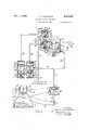
- Fig. 1 is a view, partly diagrammatic and partly crosssectioned, illustrating one form of apparatus embodying my invention.
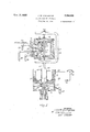
- Fig. 2 is a sectional View showing a modified form of the valve device C forming part of the apparatus illustrated in Fig. 1.
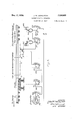
- Fig. 3 a View, partly diagrammatic and partly cross-sectioned, illustrating another form of apparatus embodying my invention.
- valve device shown in Figs. 1, 2 and 3 may be automatically controlled in accordance with the weight of a car, the speed of the car, the velocity of the wind opposing or aiding the motion of the car, and the ambient temperature to cause the car to leave the retarder at the most desirable speed.
- the reference character I designates one track rail of a stretch of railway track, which track rail, as 5 here shown, is secured to a rail support 2 mounted on an adjacent pair of the usual crossties 3, only one cross-tie being visible in the drawing.
- a car retarder Associated with the rail l is a car retarder comprising two braking bars A and A 10.
- Each of these braking bars comprises as usual a brake beam 4 and a brake shoe 5.
- the braking bars A and A are arranged to be moved toward and away from the rail I 15 through the medium of a lever 6 which is pivotally mounted at one end on a pivot pin 8 carried by the rail support 2, and a lever l which is pivotally mounted intermediate its ends on the pivot pin 8.
- the lever 6 is inclined upwardly 20 and extends away from the rail i, and is provided on its upper surface with a groove 6 which receives the braking bar A
- the one end l of the lever i is likewise inclined upwardly and extends away from the rail 1 at 25 the opposite side of the rail from the lever 6, and the other end l of the lever 'l is inclined downwardly and extends away from the rail 1
- the end i of the lever l is provided in its upper surface with a groove 30 1, similar to the groove 6 in the lever 6, which groove receives the braking bar A
- the parts are so arranged and so proportioned that if the outer or free ends of the levers 6 and l are moved apart the braking bars will be moved 35 toward the rails into their effective or braking positions.
- the brake shoes 5 When the braking bars occupy their braking positions, the brake shoes 5 will engage the oppOsite side faces of a car wheel traversing rail l and will retard the speed of the car.
- the 4.0 center of gravity of the lever 6 and braking bar A is considerably to the right of the pivot pin 8 so that this lever will normally tend to rotate in a clockwise direction about the pivot pin.
- the levers 6 and 1 are arranged to be moved apart by means of a fluid pressure motor M comprising a cylinder 9 containing a reciprocable piston H! which is attached to the inner end of a piston rod II.
- the cylinder 9 is pivotally connected with the free end of the lever 6 by means of trunnions I2 formed on the side of the cylinder and extending through bifurcations I3 formed on the lever 6, while the piston rod II is connected at its free end to the end l of the lever I by means of an adjustable eye bolt I4 and a pivot pin I5.
- Fluid pressure may be admitted to the cylinder 9on the upper side of the piston I 9 through an opening I6 which is threaded to receive a pipe I'I.
- valve mechanisi B comprising two poppet valves lB'and I9 located in a valve body 29.
- the valve I8 is guided to move vertically by means of a valve stem I8 and is biased to an upper or closed position by means of a spring I8".
- the upper end of the valve stem I8 projects into a cylinder 2
- the upper end of the cylinder 2! is constantly connected with a pipe 22 while the lower end of this cylinder is constantly connected with atmosphere through a port 23.
- the pipe 22 is adapted to be at times connected with atmosphere, and at other times connected with a source'of fluid pressure in a manner which will be made clear hereinafter; and when this pipe is connected with atmosphere, the spring I8 holds the valve I8 closed and piston H3 in its upper position, but when the pipe 22 is connected with the source of fluid pressure, the fluid pressure which is then supplied tocylinder 2
- valve I8 When valve I8 is opened, cylinder 9 of motor M is connected through pipe IT, a pipe 59, a chamber 24 formed in valve body 29, valve I8, and a chamber 25 formed in valve body 20, with a pipe 3
- valve I8 When valve I8 is closed, however, cylinder 9 is disconnected from pipe 3
- Valve I9 is guided to move vertically within the Valve body 29 by means of a valve stem Is and is biased to an upper or a closed position by means of a spring I9
- the upper end of the valve stem I9 extends into a cylinder 26 and is attached to a reciprocable piston 21.
- the upper end of thecylinder 26 is constantly connected with a pipe 28 which is at times connected with atmosphere and at other times with a source of fluid pressure in a manner to be described hereafter, while the lower end of the cylinder 26 is constantly connected with atmosphere through a port 58.
- the supply of fluid pressure to the pipe 22 is controlled by a pilot valve mechanism P comprising part of a valve device C embodying my present invention, and the supply of fluid pressure to the pipe 28 is similarly controlled by a pilot valve mechanism P which also forms part of the valve device C.
- the pilot valve mechanism P comprises an exhaust valve M and an inlet valve 42
- the exhaust valve is slidably mounted for movement between an upper position in which it is shown in the drawing, and a lower position in which it engages a valve seat 43 and the parts are so arranged that when this valve occupies its upper position, the pipe 22 will be connected. with atmosphere through a port 44 but that, when this valve is moved to its lower position, the pipe 22 will then be disconnected from atmosphere.
- the parts are further so proportioned that when this valve is being moved from its upper position to its lower position, this valve will blank the port 44 and thus disconnect the pipe 22 from atmosphere in an intermediate position in its stroke.
- the inlet valve 42 is secured to a valve stem 45 the upper end of which is slidably 45 mounted in a guideway 66 formed in the inlet valve, and the lower end of which is slidably mounted in a plug member 41
- a spring 48 surrounds the valve stem 45 between the plus, member 41 and the inlet valve, and this spring 50 constantly biases the valve stem to an upper position in which the inlet valve 42 engages a valve seat 49
- the valve stem 45 however, is adapted to be at times moved downwardly to a lower position in which the inlet valve is unseated, in response to movement of the exhaust valve to its lower position, sufficient lost motion being provided between the exhaust valve and the valve stem to insure that the inlet valve will not open until after the exhaust valve has been so moved downwardly past the position where it blanks the exhaust port 44
- the pilot valve mechanism P is similar to the pilot valve mechanism P with theexception that the parts of the pilot valve mechanism P are inverted, and the corresponding parts of the two valve mechanisms are designated by the same reference characters with suitable distinguishing exponents. It is believed, therefore, that the construction of "the pilot valve mechanism P will be understood from the foregoing description of the pilot valve mechanism P and from an inspection of the drawing without further detailed description.
- the inlet valve 42 is closed and the exhaust valve 42 is open, and under these conditions the pipe 28 is connected with atmosphere through the exhaust port 5 5
- the exhaust valve 45 is moved to its upper position, the exhaust valve first blanks the exhaust port 44 thus disconnecting the pipe 28 from atmosphere, and then engages the valve stem 45 and moves this valve stem to its upper position.
- the valve stem 45 is moved to its upper position, the pipe 28 becomes connected with the inlet port .51 with the result that this pipe is then connected with the source of fluid pressure.
- the pilot valve mechanisms P and P are controlled by an electromagnet A through the medium of a lever 39 one end of which is pivotally supported at point 40, and the other end of which extends between and cooperates with the exhaust valves M and M of the pilot valve mechanisms P and P
- the electromagnet A as here shown, is of the solenoid type and comprises a winding 32 and an armature 33.
- the armature 33 is pivotally attached at its upper end to the lever 39, and is operatively connected at its lower end with a diaphragm 34 located in a diaphragm chamber 35.
- a spring 36 constantly biases the armature 33 to an upper position in which it is shown in the drawing, and the parts are so proportioned that when the armature occupies its upper position, the lever 39 will be rotated to'an upper position in which it holds the exhaust valve- H of the pilot valve mechanism P in its upper position and permits the exhaust valve 4 I of the pilot valve mechanism P to move to its upper position under the bias of the spring 50
- the diaphragm chamber 35 is constantly connected with atmosphere on the upper side of the diaphragm 34 by means of a port 31, and with the pipe I!
- the supply of current to the electromagnet A is controlled by a variable impedance R over a circuit which includes the winding 32 of the electromagnet A, a single pair of wires 52 and 53, a suitable source of current here shown as a battery D, and the impedance.
- the impedance R may be located at any suitable point but will usually be located at a point remote from the braking apparatus as in the-control cabin of a classification yard car retarder system. The parts are so proportioned that the pull exerted by the electromagnet is proportional to the angular displacement of the arm from its oil position.
- arm 63 of impedance R occupies a position in which it is out of r0 engagement with the impedance, which position I shall term its 0 position, and under these conditions, winding 32 of electromagnet A is deenergized. As a result no force is exerted on the armature by the electromagnet, and spring 33 15 therefore holds the armature in its upper position.
- inlet valve 42 of pilot valve mechanism P will close and will cut ofl the supply of fluid pressure to pipe 22, but valve i8 of valve mechanism B will not immediately become closed because, for the reasons previously pointed out, the exhaust valve il of mechanism P will then still be closed; and fluid will therefore be trapped inrpipe 22 and in cylinder 2%, which will hold this pilot valve open.
- suificient additional fluid will have been supplied to cylinder 9 to cause armature 33 to move to a position in which the exhaust valve M of the pilot valve mechanism P becomes opened, and when this happens, the fluid which was trapped in pipe 22 and in cylinder 2!
- valve 58 will then close and will cut ofl any further supply of fluid to cylinder 9.
- armature 33 which position I shall, for convenience (term its intermediate position, exhaust valve M of pilot valve mechanism P will be open and inlet valve Q2 of this pilot valve mechanism will be closed, so that valve 19 of valve mechanism B will remain closed, and the fluid which was previously supplied'to cylinder 9 will therefore be trapped in this cylinder.
- the electromagnet B is so constructed that the downward pull exerted on the armature 33 increases as the magnitude of the current supplied to the winding 32 increases, and since the upward force which must be exerted on the armature by the diaphragm 34 to move the armature to its intermediate position depends upon the pressure of the fluid supplied to cylinder 9, it follows that by properly proportioning the parts, the apparatus can be made to supply fluid pressure to cylinder 9 in such manner that the pressure of the fluid in the cylinder will increase as the arm 68 of impedance R is moved toward the left to decrease the amount of the impedance R which is connected in the circuit for the winding 32.
- arm 60 of impedance R is restored to its off position in which it is shown in the drawings.
- This movement of the impedance arm deenergizes winding 32,0f electromagnet A, and when this winding becomes deenergized, the pressure of the fluid in cylinder 9 causes diaphragm 34 to exert an upward force on armature 33 which force, together with that exerted on the armature by the biasing spring 36, moves the armature to its upper po-' sition, thereby causing exhaust valve 41 of valve mechanism P to become closed and inlet valve 42 of this valve mechanism to become opened.
- valve I9 therefore becomes opened and exhausts fluid from cylinder 9 of motor M.
- the braking bars gradually return to their non-braking positions by gravity, and when the braking bars have reached their full non-braking positions, all parts; are restored to their normal positions in which they are illustrated in the drawings.
- valve device C comprises a slide valve 53 operatively connected with the armature 33 of electromagnet A through the medium of an operating rod 84 and a yoke 65.
- the slide valve 63 and operating rod 64 are mounted to slide vertically in a valve chamber 6'!
- valve device 0 Formed in the body of the valve device 0 are three ports H, 12 and 13, the outer ends of which are connected respectively with the pipes 22 and 28 and with atmosphere; and formed in the valve body are two ports 14 and 15 and a cavity 16 which c0,- operate with the ports H, 12 and I3 to selectively connect the ports 'H and 12 with the valve chamber 6?
- valve stem 86 biased to an upper position by means of a spring 8
- Each valve stem 88 controls an inlet valve 8
- valve stem 80 of this valve moves downwardly against the bias exerted by the associated. spring 8
- valve V is deener gized, however, as shown in the drawings, pipe 22 is disconnected from pipe 3
- valve stem 88 of this valve moves down wardly and connects pipe 28 with pipe 3
- the valves V and V are controlled by a relay device C comprising a contact plate 86 secured to, but insulated from, armature 33* of electromagnet A.
- the contact plate 86 cooperates with four adjustable contact screws 81, 88, 89, and 90 mounted on an insulating support 9
- the armature 33 of electromagnet A is operatively connected with diaphragm 34 in the same manner as was previously described in connec- 5 tion with Fig.- l, and the winding 32 of electromagnet A iscontrolled by the impedance R in the same manner as was previously described in connection with Fig. 1.
- winding 82 of valve V is energized over a circuit which passes from battery D through wires 95 and 94, contact 81-86-88, wire 93",, winding 82 of valve V and wire 92,
- valve V becomes deenergized and causes valve l8 to close, thereby cutting ofi the further supply of fluid pressure to cylinder 9.
- armature 33 will remain inthe position in which both the contacts 81-86-88 and 89-86-90 of device 0 are open until the 7.0 pressure in cylinder 9 increases or decreases or until arm 60 of impedance R is moved to vary the energization of winding 32 of electromagnet A. If the pressure in cylinder 9- increases, while the; armature is in its intermediate position, 'v
- armature 33 will move upwardly and close contact 81-86-433, thereby energizing valve V and hence causing valve I9 to open and vent fluid from cylinder 9 until the pressure in the cylinder again decreases sufliciently to permit magnet A to move the armature downwardly far enough to open the contact 81--86-88.
- the armature 33 will move downwardly and close contact 89-86-90, thereby causing valve V to become energized, and 'hence causing valve l8 to open and admitsufiicient additional pressure to cylinder 9 to restore armature 33 to its intermediate position.
- armature 33 when the armature 33 occupies its intermediate position, arm 60 of impedance R is moved, armature 33 will move downwardly and close contact 89-8690 or will move upwardly and close contact 8'
- the speed at which the cars enter the car retarders varies through wide limits depending, among other things, upon the speed at which the cars go over the hump, the ambient temperature, the direction and. velocity of the wind, and the weight of the cars and their contents.
- car retarder indicated diagrammatically at E in the drawings.
- This car retarder is preferably of the type shown in Fig. 1, and is controlled by means of control apparatus similar to that shown in Figs. 1, 2, or 3, this control apparatus being indicated diagrammatically in the drawings by the rectangle F, and by the winding 32 of the electromagnet A.
- the winding 32 is connected in a circuit which includes the battery B and five impedances R, R R R and R These impedances are similar in general construction and each is provided with a plurality of taps Hit and with an arm loi which is pivoted at one end at [32 and which coacts at its free end with the taps l'tfi.
- of the impedance R is operatively connected with suitable means for varying this impedance in accordance with the velocity of the wind acting in a direction to slow up the car traversing the stretch S, these means, in the particular form here illustrated, comprising a governor I06 driven by a windmill I03, and operatively connected with the arm ifll in such manner that the greater the wind velocity in the direction to slow up the car, the more will be the amount of the impedance R that is included in the circuit for the winding 32.
- the arm ifll of the impedance R is operatively connected with suitable means for] varying this impedance in accordance with the velocity of the wind acting in the direction to speed up a car traversing the stretch S of track, this means as here shown, comprising a governor H34 driven by a windmill I05, and operatively connected with the arm HM in such a manner that the greater the wind velocity in a direction to speed up the car, the less will be the amount of the impedance R which is included in the circuit for the winding 32 of electromagnet A.
- the arm ID! of the impedance R is operatively connected with car speed measuring means indicated diagrammatically in the drawings by r passing the measuring means, the less will be;
- of the impedance R is operatively connected with a scale H which is associated with the stretch S to the left of the car speed measuring means G.
- the scale H controls the impedance arm I04 in such manner that the heavier the car on the scale is, the less will be the amount of the impedance R that is included in the circuit for the winding 32, and that when the car moves off of the scale, the amount of the impedance which is then included in the circuit for the winding will remain in the, circuit until the next car moves onto the scale.
- the arm I0! of the impedance R is operative- 1y connected with temperature responsive means here shown as a bimetallic strip J in the form of a coil.
- the strip J is so arranged and the parts are so prop rtioned that the higher the ambient temperature becomes, the less will be the amount of the impedance R which is included in the winding 32.
- the strength of the current supplied to the winding 32 will depend upon the sum of the amounts of the individual impedances which are included in the circuit, and it follows that the strength of this current will vary with the variations in each of the individual impedances. Since, as was previously pointed out, the braking forces exerted by the car retarder varies with the strength of the current supplied to the winding 32, it will be apparent that by properly proportioning the parts, the braking force exerted by the car retarder may be controlled in a manner which will cause the cars to leave the retarder at the most suitable speed to cause them to coast to their ultimate designation.
- a car retarder a fluid pressure motor for operating said car retarder, a first fluid pressure operated valve for controlling the admission of fluid to said motor, a second fluid pressure operated valve for controlling the exhaust of fluid from said motor, a valve device comprising an armature biased to one position, a winding effective when energized for exerting a force on said armature which opposes that due to its bias and which is proportional to the strength of the current supplied to said winding, a diaphragm subjected to the pressure of the fluid in said motor and operatively connected with said armature in such manner that when fluid pressure is supplied to said motor said diaphragm will exert a force on said armature which opposes that due to the energization of said winding, and means controlled by said armature for selectively controlling the admission and exhaust of fluid to said two fluid pressure operated valves.
- a car retarder a fluid pressure operated motor for operating said car retarder, two fluid pressure operated valves, means controlled by the one valve for controlling the admission of fluid pressure to said motor, means controlledv by the other valve for controlling the exhaust or" fluid pressure from said motor, two valve mechanisms, means controlled by the one valve mechanism for controlling the admission of fluid pressure to and exhaust of fluid pressure from said one valve, means controlled by the other valve mechanism for controlling the admission of fluid pressure to and exhaust of fluid pressure from said other valve, an electromagnet comprising an armature and a winding, means for biasing said armature to one position in such manner that whensaid winding is energized said armature will move to another position in opposition to its bias, a diaphragm subjected to the pressure of the fluid in said motor and operatively connected with said armature in such manner that when fluid pressure is supplied to said motor said diaphragm will exert a force on the armature which opposes that due to the energization of said winding, and means con- 5
- a car retarder a fluid pressure motor for operating said car retarder, a first fluid pressure operated valve for controlling the admission of fluid to said motor, a second fluid pressure operated valve for controlling the exhaust of fluid from said motor, a valve device including an armature, a winding effective when energized for exerting a pull on said armature which varies with the strength of the current supplied to said winding, a diaphragm subjected to the pressure of the fluid in said motor and operatively connected with said armature in such manner that when fluid pressure is supplied to said motor said diaphragm will exert a force on said armature which opposes that due to the energization of said winding, means for supplying said winding with current at different strengths, a spring effective when said winding is deenergized for moving said armature to one extreme position, means controlled by said armature and effective wh n said armature occupies its one extreme position for connecting the second fluid pressure operated valve with a source of fluid pressure and the first fluid pressure operated
- a car retarder for operating said car retarder, a member movable between an intermediate and two extreme positions, two fluid pressure valves, means controlled by the one valve for admitting fluid pressure to said motor, means controlled by the other valve for exhausting fluid pressure from said motor; means controlled by said member for connecting the one valve with a source of fluid pressure and the other valve with atmosphere when the member occupies its one extreme position, for connecting the other valve with a source of fluid pressure and the one valve with atmosphere when the member occupies its other extreme position, and for connecting both valves with atmosphere when the member occupies its intermediate extreme position, means for biasing said member to its other extreme position, a winding, means for energizing said winding, means effective when said winding becomes energized for moving said member to its one extreme position in opposition to the bias of said spring with a force which depends upon the strength of the current supplied to said winding, and means responsive to the pressure of the fluid in said device for moving said member from its one extreme position to its intermediate position whenthe pressure of
- a car retarder a fluid pressure motor for operating said car retarder
- a valve device including an armature biased to one end of its stroke'by a spring, a winding efiective when energized. for moving said armature from said one'end of its stroke to the other end of its stroke, a diaphragm operatively connected with said armature and having one side subjected to the pressure of the fluid in said motor, the parts being so proportioned that as thepressure of the fluid in said motor builds up some pressure will be reached at which the diaphragm will exert a force on the armature which together with the force exerted on the armature by its bias will be suflicient to move the armature from its other end of its stroke to an intermediate position, two valve mechanisms each including an inlet valve and an exhaust valve, means controlled by said armature for controlling said two valve mechanisms in such manner that when the armature is moved to said one end of its stroke the inlet valve of the one mechanism and the exhaust valve of the other
- a car retarder a fluid pressure motor for operating said car retarder
- a valve device including an armature biased to one end of its stroke by a spring, a winding efiective when energized for moving said armature from said one end of its stroke to the other end of its stroke, a diaphragm operatively connected with said armature and having one side subjected to the pressure of the fluid in said motor, the parts being so proportioned that as the pressure of the fluid in said motor builds up some pressure will be reached at which the diaphragm will exert a force on the armature which together with the force exerted on the armature by its bias will be sufficient to move the armature from its other end of its stroke to an intermediate position, two valve mecha nisms each including an inlet valve and an exhaust valve; means controlled by said armature for controlling said two valve mechanisms in such manner that when the armature is moved to said one end of its stroke the inlet valve of the one mechanism and the exhaust valve of the other mechanism will
- a car retarder a fluid pressure motor for operating said car retarder
- a valve device including an armature biased to one end of its stroke by a spring, a winding efiective when energized for moving said armature from said one end of its stroke to the other end of its stroke, a diaphragm operatively connected with said armature and having one side subjected to the pressure of the'fluid in said motor, the parts being so proportioned that as the pressure of the fluid in said motor builds up some pressure will be reached at which the diaphragm will exert a force on the armature which together with the force exerted on the armature by its bias will be sufiicient to move the armature from its other end of its stroke to an intermediate position, two valve mechanisms each including an inlet valve biased to a closed position and an exhaust valve biased to an open position, the exhaust valve of each mechanism being operatively connected with the inlet valve in such manner that the inlet valve is moved to its open position by
- a car retarder a fluid pressure motor for operating said car retarder
- a valve device including an armature biased to one end of its stroke by a spring, a winding effective when energized for moving said armature from said one end of its stroke to the other end of its stroke, a diaphragm operatively connected with said armature and having oneside subjected to the pressure of the fluid in said motor, the parts being so proportioned that as the pressure of the fluid in said motor builds up some pressure will be reached at which the diaphragm will exert a force on the armature which together with the force exerted on the armature by its bias will be suflicient to move the armature from its other end of its stroke to an intermediate position, a slide valve operatively connected with said armature to move therewith, a first fluid pressure operated pneumatic valve biased to a closed position for con-.
- a second fluid pressure operated valve biased to a closed position for "controlling the admission of fluid pressure to said motor
- means controlled by said slide valve for connecting said first fluid pressure operated valve with a source of fluid pressure to open said first valve when and only when said armature occupies its one extreme position and for connecting said first valve with atmosphere to permit said first valve to close when said armature occupies its intermediate or its other extreme position
- other means controlled by said slide valve for connecting said second fluid pressure operated valve with a source of fluid pressure to open said second valve when and only when said armature occupies its other extreme position and for connecting said second valve with atmosphere to permit said second valve to close when said armature occupies its intermediate or its one extreme position.
- railway braking apparatus comprising two braking bars movable toward and away from the track rails into braking and non-braking positions and biased to a braking position, a fluid pressure operated motor for moving said braking bars to their braking positions, a first fluid pressure operated valve for controlling the exhaust of fluid pressure from said motor, a second fluid pressure operated valve for controlling the admission of fluid pressure to said motor, a first electrically operated pilot valve mechanism for controlling the supply of fluid pressure to said first fluid pressure operated valve, a second electrically operated pilot valve machanism for controlling the supply of fluid pressure to said second fluid pressure operated valve, a valve device comprising an' armature biased to one position, a winding for moving said armature from its one position to another position, the parts being so proportioned that when said winding is energized the resultant force exerted on said armature will be proportional to the strength of the current supplied to said winding, means for supplying said winding with current at different strengths, a diaphragm subjected to the pressure of the fluid in said fluid pressure
- a fluid pressure motor a first fluid pressure operated valve for controlling the admission of fluid to said motor, a second fluid pressure operated valve for controlling the exhaust of fluid from said motor, a valve device comprising an armature biased to one position, a winding effective when energized for exerting a force on said armature which opposes that due to its bias and which is proportional to the strength of the current suppiied to winding, a diaphragm subjected to the pressure of the fluid in said motor and operatively connected with said armature in such manner that when fluid pressure is supplied to said motor said diaphragm will exert a force on said armature which opposes that due to the energization of said winding, and means controlled by said armature for selectively controlling the admission and exhaust of fluid to said two fluid pressure operated valves.
- a fluid pressure motor two fluid pressure operated valves, means controlled by the one valve for controlling the admission of fluid, pressure to said motor, means controlled by the other valve for controlling the exhaust of fluid pressure from said motor, two valve mechanisms, means controlled by the one valve mechanism for controlling the admission of fluid pressure to and exhaust of fluid pressure from said one valve, means controlled by the other valve mechanism for controlling the admission of fluid pressure to and exhaust of fluid pressure from said other valve, anelectromagnet comprising an armature and a winding, means for biasing said armature to one position in such manner that when said winding is energized said armature will move to another position in opposition to its bias, a diaphragm subjected to the pressure of the fluid in said motor and operatively connected with said armature in such manner that when fluid pressure is supplied to said motor said diaphragm will exert a force on the armature which opposes that due to the energization of said winding, and means controlled by said armature for selectively controlling said two valve mechanisms.
- a fluid pressure motor a first fluid pressure operated valve for controlling the admission of fluid to said motor, a second fluid pressure operated valve for controlling the exhaust of fluid from said motor, a valve device including an armature, a winding effective when energized for exerting a pull on said armature which varies with the strength of the current supplied to said winding, a diaphragm subjected to the pressure of the fluid in said motor and operatively connected with said armature in such manner that when fluid pressure is supplied to said motor said diaphragm will exert a force on said armature which opposes that due to the energization of said winding, means for supplying said winding with current at different strengths, a spring effective when said winding is deenergized for moving said armature to one extreme position, means controlled by said armature and effective when said armature occupies its one extreme position for connecting the second fluid pressure operated valve with a source of fluid pressure and the first fluid pressure operated valve with atmosphere, means controlled by said armature and effective when
- a fluid pressure motor a member movable between an intermediate and two extreme positions, two fluid pressure valves, means controlled by the one valve for admitting fluid pressure to said motor, means controlled by the other valve for exhausting fluid pressure from said motor; means controlled by said member for connecting the one winding, means for energizing said winding,
Landscapes
- Engineering & Computer Science (AREA)
- Mechanical Engineering (AREA)
- Magnetically Actuated Valves (AREA)
Description
1935 J. w. LIVINGSTQN 2,024,935
RAILWAY BRAKING APPARATUS Filed May 16, 1934 4 Sheets-Sheet 1 Tommce 0f Fim'd Pmwsuwe A 5 I 5 1 I6 4 4 6 9 INVENTOR Jahn W Lz'm'rzgszon HIS ATTORNEY Dec. 17, 1935. J. w. LIVINGSTQN RAILWAY BRAK ING APPARATUS Filed Ma 16, 193 4 Sheets-Sheet 2 INVENTOR John W. llzvmgyzon Hi5 A TTORNEY Dec. 17, 1935., J. w. LIVINGSTQN 2,@24,935
RAILWAY BRAKING APPARATUS Filed May 16, 1934 4 Sheets-Shet 3 [08a Zmfian 0 Source of Fluid Pp rwum Fig. 5.
INVENTOR Jbim WLwwgJzon 5 7 BY HIS AZTORNEY 1935- J. w. LIVINGSTON 2,@24,935
RAILWAY BRAKING APPARATUS Filed May 16, 1954 4 Sheets-Sheet 4.
Rm H w? n Wm A w L m WQH m w @Q R Q a a QE I Patented Dec. 17, 1935 UNITED STATES PATNT OFFIE RAILWAY BRAKING APPARATUS Application May 16, 1934, Serial No. 725,959
13 Claims.
My invention relates to railway braking apparatus, and particularly to braking apparatus of the type employed in classification car retarder yards to control th speed of the cars entering the various classification tracks. More particularly my present invention relates to braking apparatus of the type in which the braking bars of a car retarder are arranged to be moved toward the associated track rail to their braking positions by a fluid pressure operated motor or motors, and to be restored to their non-braking positions by suitable biasing means such as gravity.
One object of my invention is to provide novel means for controlling the supply of fluid pressure to the car retarder motor or motors from a remote point over a single pair of line wires.
Another object of my invention is to provide novel means for controlling the supply of fluid pressure to the car retarder motor or motors in such manner that any desired pressure within the limits of the source may be obtained in the motor or motors.
A further object of my invention is to provide novel means for controlling the supply of fluid pressure to the car retarder motor or motors in such manner that the pressure of the fluid in the motor or motors may be readily varie automatically in accordance with the weight of the car whose speed is to be retarded, the speed of the car, the velocity of the wind acting to oppose or aid the speed of the car, and the ambient temperature, whereby all cars will enter the classification tracks at the most desirable speeds.
I will describe several forms of apparatus embodying my invention, and will then point out the novel features thereof in claims.
In the accompanying drawings, Fig. 1 is a view, partly diagrammatic and partly crosssectioned, illustrating one form of apparatus embodying my invention. Fig. 2 is a sectional View showing a modified form of the valve device C forming part of the apparatus illustrated in Fig. 1. Fig. 3 a View, partly diagrammatic and partly cross-sectioned, illustrating another form of apparatus embodying my invention.
4 is a diagrammatic View showing the manher in which the valve device shown in Figs. 1, 2 and 3 may be automatically controlled in accordance with the weight of a car, the speed of the car, the velocity of the wind opposing or aiding the motion of the car, and the ambient temperature to cause the car to leave the retarder at the most desirable speed.
Similar reference characters refer to similar parts in each of the several views.
Referring to the drawings, the reference character I designates one track rail of a stretch of railway track, which track rail, as 5 here shown, is secured to a rail support 2 mounted on an adjacent pair of the usual crossties 3, only one cross-tie being visible in the drawing. Associated with the rail l is a car retarder comprising two braking bars A and A 10.
located on opposite sides of the rail. Each of these braking bars comprises as usual a brake beam 4 and a brake shoe 5.
The braking bars A and A are arranged to be moved toward and away from the rail I 15 through the medium of a lever 6 which is pivotally mounted at one end on a pivot pin 8 carried by the rail support 2, and a lever l which is pivotally mounted intermediate its ends on the pivot pin 8. The lever 6 is inclined upwardly 20 and extends away from the rail i, and is provided on its upper surface with a groove 6 which receives the braking bar A The one end l of the lever i is likewise inclined upwardly and extends away from the rail 1 at 25 the opposite side of the rail from the lever 6, and the other end l of the lever 'l is inclined downwardly and extends away from the rail 1| below the lever 6. The end i of the lever l is provided in its upper surface with a groove 30 1, similar to the groove 6 in the lever 6, which groove receives the braking bar A The parts are so arranged and so proportioned that if the outer or free ends of the levers 6 and l are moved apart the braking bars will be moved 35 toward the rails into their effective or braking positions. When the braking bars occupy their braking positions, the brake shoes 5 will engage the oppOsite side faces of a car wheel traversing rail l and will retard the speed of the car. The 4.0 center of gravity of the lever 6 and braking bar A is considerably to the right of the pivot pin 8 so that this lever will normally tend to rotate in a clockwise direction about the pivot pin. Similarly, the center of gravity of the lever I 45 and braking bar A is to the left of the pivot pin .8 so that this lever will normally tend to rotate in a counter-clockwise direction about the pivot pin 8. It will be apparent, therefore, that when no force is applied to the free ends of the 50 levers 6 and l to move them apart, the free ends of these levers will move toward each other, thereby moving the braking bars to their ineifective or non-braking positions in which they are illustrated in the drawings.
The levers 6 and 1 are arranged to be moved apart by means of a fluid pressure motor M comprising a cylinder 9 containing a reciprocable piston H! which is attached to the inner end of a piston rod II. The cylinder 9 is pivotally connected with the free end of the lever 6 by means of trunnions I2 formed on the side of the cylinder and extending through bifurcations I3 formed on the lever 6, while the piston rod II is connected at its free end to the end l of the lever I by means of an adjustable eye bolt I4 and a pivot pin I5. Fluid pressure may be admitted to the cylinder 9on the upper side of the piston I 9 through an opening I6 which is threaded to receive a pipe I'I. When fluid pressure is admitted to the cylinder 9 through the pipe I? and opening I6, the piston I is forced downwardly and the cylinder 9' upwardly, thereby separating the levers 6 and "I, and hence moving the braking 'bars toward their effective or braking positions. It will be obvious that when the braking bars are moved to their braking positions, they will exert a. braking force which is proportional to the pressure of the fluid supplied to the cylinder 9.
The supply of fluid pressure to the cylinder 9 is controlled by means of a valve mechanisi B comprising two poppet valves lB'and I9 located in a valve body 29. The valve I8 is guided to move vertically by means of a valve stem I8 and is biased to an upper or closed position by means of a spring I8". The upper end of the valve stem I8 projects into a cylinder 2| which is formed in the upper part of the casing 29 in axial alignment with the valve l8, and is attached to a piston I 8 which is mounted to reciprocate in the cylinder 2i. The upper end of the cylinder 2! is constantly connected with a pipe 22 while the lower end of this cylinder is constantly connected with atmosphere through a port 23. The pipe 22 is adapted to be at times connected with atmosphere, and at other times connected with a source'of fluid pressure in a manner which will be made clear hereinafter; and when this pipe is connected with atmosphere, the spring I8 holds the valve I8 closed and piston H3 in its upper position, but when the pipe 22 is connected with the source of fluid pressure, the fluid pressure which is then supplied tocylinder 2| forces piston I8 to its lower position, thereby opening valve I8. When valve I8 is opened, cylinder 9 of motor M is connected through pipe IT, a pipe 59, a chamber 24 formed in valve body 29, valve I8, and a chamber 25 formed in valve body 20, with a pipe 3| which is constantly supplied with fluid pressure, usually air, from a suitable source not shown in the drawing. When valve I8 is closed, however, cylinder 9 is disconnected from pipe 3|. It follows therefore that when valve I8 is opened, fluid pressure will be supplied to cylinder 9 of motor M to move the braking bars to their braking positions, but that, when this valve is closed, the supply of fluid pressure to cylinder 9 will be cut off.
Valve I9 is guided to move vertically within the Valve body 29 by means of a valve stem Is and is biased to an upper or a closed position by means of a spring I9 The upper end of the valve stem I9 extends into a cylinder 26 and is attached to a reciprocable piston 21. The upper end of thecylinder 26 is constantly connected with a pipe 28 which is at times connected with atmosphere and at other times with a source of fluid pressure in a manner to be described hereafter, while the lower end of the cylinder 26 is constantly connected with atmosphere through a port 58. When the pipe 28 is connected with the source of fluid pressure, the fluid pressure which is then supplied to cylinder 26 forces piston 2'! to its lower position in opposition to the bias of spring I9 thereby opening valve I9, and under these conditions cylinder 9 of motor M becomes connected with atmosphere through pipes I1 and 59, chamber 24, valve I9, a chamber 39 formed in the valve body 20, and a port 60. When pipe 28 is connected with atmosphere, however, spring I9 moves valve l9 to its closed position and piston 21 toits upper position, thus disconnecting cylinder 9 from atmsophere. As was previously pointed out, when cylinder 9 is connected with atmosphere, the braking bars A and A move to their non-braking positions under the influence of gravity.
The supply of fluid pressure to the pipe 22 is controlled by a pilot valve mechanism P comprising part of a valve device C embodying my present invention, and the supply of fluid pressure to the pipe 28 is similarly controlled by a pilot valve mechanism P which also forms part of the valve device C. As here illustrated, the pilot valve mechanism P comprises an exhaust valve M and an inlet valve 42 The exhaust valve is slidably mounted for movement between an upper position in which it is shown in the drawing, and a lower position in which it engages a valve seat 43 and the parts are so arranged that when this valve occupies its upper position, the pipe 22 will be connected. with atmosphere through a port 44 but that, when this valve is moved to its lower position, the pipe 22 will then be disconnected from atmosphere. The parts are further so proportioned that when this valve is being moved from its upper position to its lower position, this valve will blank the port 44 and thus disconnect the pipe 22 from atmosphere in an intermediate position in its stroke. The inlet valve 42 is secured to a valve stem 45 the upper end of which is slidably 45 mounted in a guideway 66 formed in the inlet valve, and the lower end of which is slidably mounted in a plug member 41 A spring 48 surrounds the valve stem 45 between the plus, member 41 and the inlet valve, and this spring 50 constantly biases the valve stem to an upper position in which the inlet valve 42 engages a valve seat 49 The valve stem 45 however, is adapted to be at times moved downwardly to a lower position in which the inlet valve is unseated, in response to movement of the exhaust valve to its lower position, sufficient lost motion being provided between the exhaust valve and the valve stem to insure that the inlet valve will not open until after the exhaust valve has been so moved downwardly past the position where it blanks the exhaust port 44 The exhaust valve M is constantly biased to its upper position by means of a spring 50 which surrounds the valve stem 45 between the two valves, this latter 2 spring being so constructed that when it becomes compressed due to the downward movement of the exhaust valve, it will not exert suflicient force on the inlet valve to unseat this lat ter valve. When the inlet valve 42 is unseated, the pipe 22 .is connected with an inlet port 5i which is constantly connected with the pipe EI, and it will be apparent that under these conditions, the pipe 22 will be supplied with fluid pressure. When, however, the inlet valve is seated, the pipe 22 is disconnected from the inlet port 5!, and the supply of "fluid pressure to the pipe '22 is then cut off. It should be particularly pointed :out that with the pilot valve mechanism P constructed in the manner just described, under no conditions will the exhaust and inlet valves both become opened at the same time, thus guarding against the fluid waste and the possible unstable operation which would occur in the event that both of these valves did be come opened at the same time.
The pilot valve mechanism P is similar to the pilot valve mechanism P with theexception that the parts of the pilot valve mechanism P are inverted, and the corresponding parts of the two valve mechanisms are designated by the same reference characters with suitable distinguishing exponents. It is believed, therefore, that the construction of "the pilot valve mechanism P will be understood from the foregoing description of the pilot valve mechanism P and from an inspection of the drawing without further detailed description. When the exhaust valve 4! of the pilot valve mechanism P occupies its lower position, the inlet valve 42 is closed and the exhaust valve 42 is open, and under these conditions the pipe 28 is connected with atmosphere through the exhaust port 5 5 When, however, the exhaust valve 45 is moved to its upper position, the exhaust valve first blanks the exhaust port 44 thus disconnecting the pipe 28 from atmosphere, and then engages the valve stem 45 and moves this valve stem to its upper position. When the valve stem 45 is moved to its upper position, the pipe 28 becomes connected with the inlet port .51 with the result that this pipe is then connected with the source of fluid pressure.
The pilot valve mechanisms P and P are controlled by an electromagnet A through the medium of a lever 39 one end of which is pivotally supported at point 40, and the other end of which extends between and cooperates with the exhaust valves M and M of the pilot valve mechanisms P and P The electromagnet A, as here shown, is of the solenoid type and comprises a winding 32 and an armature 33. The armature 33 is pivotally attached at its upper end to the lever 39, and is operatively connected at its lower end with a diaphragm 34 located in a diaphragm chamber 35. A spring 36 constantly biases the armature 33 to an upper position in which it is shown in the drawing, and the parts are so proportioned that when the armature occupies its upper position, the lever 39 will be rotated to'an upper position in which it holds the exhaust valve- H of the pilot valve mechanism P in its upper position and permits the exhaust valve 4 I of the pilot valve mechanism P to move to its upper position under the bias of the spring 50 The diaphragm chamber 35 is constantly connected with atmosphere on the upper side of the diaphragm 34 by means of a port 31, and with the pipe I! on the lower side of the diaphragm by means of .a pipe 38, and it follows that when fluid pressure is supplied to cylinder 9 of motor M, diaphragm 34 will exert an upward pressure on the armature which is proportional to the pressure of the fluid supplied to cylinder 9.
The supply of current to the electromagnet A is controlled by a variable impedance R over a circuit which includes the winding 32 of the electromagnet A, a single pair of wires 52 and 53, a suitable source of current here shown as a battery D, and the impedance. The impedance R may be located at any suitable point but will usually be located at a point remote from the braking apparatus as in the-control cabin of a classification yard car retarder system. The parts are so proportioned that the pull exerted by the electromagnet is proportional to the angular displacement of the arm from its oil position.
As shown in the drawings, arm 63 of impedance R occupies a position in which it is out of r0 engagement with the impedance, which position I shall term its 0 position, and under these conditions, winding 32 of electromagnet A is deenergized. As a result no force is exerted on the armature by the electromagnet, and spring 33 15 therefore holds the armature in its upper position. As was previously pointed out, when the armature occupies its upper position, lever 39 is rotated to its upper position, and due to the previously described proportioning of the parts, when 20 the lever 39 occupies its upper position, exhaust valve M of pilot valve mechanism P is open, inlet valve 42 of pilot valve mechanism P is closed, exhaust valve 4 I of pilot valve mechanism 9 is closed, and inlet valve 42 of pilot valve 25 mechanism P is open. Pipe 22 is therefore connected with atmosphere, while pipe 28 is connected with the source of fluid pressure, thus causing valve l8 of valve mechanism B to be closed and valve H) of this valve mechanism to be opened, 3'0 and hence causing cylinder 9 to be disconnected from the source of fluid pressure and to be connected with atmosphere. Since cylinder 9 is disconnected from the source of fluid pressure and is connected with atmosphere, the braking bars A 35 and A of the car retarder are held by gravity in their non-braking positions.
In explaining the operation of the apparatus as a whole, I will assume that the operator, wishing to make a brake application, moves arm 4'0 (ill of impedance R from its off position to an on position. Under these conditions, the resultant energization of winding 32 causes a downward force proportional to the angular displacement of the lever fill to be exerted on armature 45 33, and armature 33 therefore moves downwardly in opposition to the bias of spring 36, thereby moving both lever 33 and diaphragm 34 downwardly. The downward movement of lever 38 first permits spring 48 to close inlet valve 42 of 5 pilot valve mechanism P and then permits spring 55 to subsequently open the exhaust valve 4! of pilot valve mechanism P thereby causing pipe 23 to become disconnected from the source of fluid pressure and to become connected 55 to atmosphere. When pipe 28 becomes connected with atmosphere, the pressure in this pipe and in the upper end of cylinder 23 decreases rapidly, and as soon as the pressure has decreased to a predetermined value, spring 19 0 closes valve 1 9, thus disconnecting cylinder 9 from atmosphere. The downward movement of lever 39 also causes the exhaust valve M of pilot valve mechanism P to close, and inlet valve 42 of pilot valve mechanism P to subsequently 55 open, thereby causing fluid pressure to be supplied to pipe 22, and hence to cylinder 2| of valve mechanism B. The fluid pressure thus supplied to cylinder 2'! opens valve l8 which, in turn, admits iiuid at full line pressure to cylinder 3 To to move the braking bars to their braking positions. As the pressure in cylinder 9 increases, the pressure on the underside of diaphragm 34 also increases, thus causing this diaphragm to exert an upward force on armature 33 which is 75 proportional to the pressure of the fluid in the cylinder. The biasing spring 36, of course, also exerts an upward force on armature 33, and the parts are so proportioned that as the pressure in cylinder 9 continues to build up, a pressure will finally be reached at which the combined 'upward force exerted on the armature by diaphragm 3d and by spring 35 will exceed the downward force exerted on the armature due to the pull of the electromagnet, and when this happens, the armature 33 will start to move upwardly and move lever 39 upwardly. As soon as lever 39 starts to move upwardly, inlet valve 42 of pilot valve mechanism P will close and will cut ofl the supply of fluid pressure to pipe 22, but valve i8 of valve mechanism B will not immediately become closed because, for the reasons previously pointed out, the exhaust valve il of mechanism P will then still be closed; and fluid will therefore be trapped inrpipe 22 and in cylinder 2%, which will hold this pilot valve open. However, after a brief interval of time, suificient additional fluid will have been supplied to cylinder 9 to cause armature 33 to move to a position in which the exhaust valve M of the pilot valve mechanism P becomes opened, and when this happens, the fluid which was trapped in pipe 22 and in cylinder 2! will be vented to atmosphere, and valve 58 will then close and will cut ofl any further supply of fluid to cylinder 9. In this latter position of the armature 33, which position I shall, for convenience (term its intermediate position, exhaust valve M of pilot valve mechanism P will be open and inlet valve Q2 of this pilot valve mechanism will be closed, so that valve 19 of valve mechanism B will remain closed, and the fluid which was previously supplied'to cylinder 9 will therefore be trapped in this cylinder. As was previously pointed out, the electromagnet B is so constructed that the downward pull exerted on the armature 33 increases as the magnitude of the current supplied to the winding 32 increases, and since the upward force which must be exerted on the armature by the diaphragm 34 to move the armature to its intermediate position depends upon the pressure of the fluid supplied to cylinder 9, it follows that by properly proportioning the parts, the apparatus can be made to supply fluid pressure to cylinder 9 in such manner that the pressure of the fluid in the cylinder will increase as the arm 68 of impedance R is moved toward the left to decrease the amount of the impedance R which is connected in the circuit for the winding 32.
It should be particularly pointed out that if, when the armature 33 occupies its intermediate position, the pressure of the fluid in cylinder 9 should increase for any reason, as might happen when a car enters the retarder and forces the braking bars away from the rail 1, the resultant increase in force exerted on diaphragm 34 will cause the armature 33 to move upwardly past its intermediate position to a position in which the exhaust valve 41 of pilot valve mechanism P becomes closed and the inlet valve 42 becomes opened, and when this happens, fluid pressure will be supplied to pipe 28. As a result, valve I!) will then open and will vent fluid from cylinder 9 to atmosphere until the pressure of the fluid in cylinder 9 again decreases sufficiently to permit the armature to return to its intermediate position. As soon as the armature returns to its intermediate position, inlet valve 42 of pilot valve mechanism P will again become closed, and exhaust valve will again become opened, thus permitting valve [9 to again become closed. Likewise, if when the armature occupies its intermediate position, the pressure in cylinder 9 should decrease for any reason, as for example would be the case if the cylinder 9 leaked, armature 33 will move downwardly and will operate pilot valve mechanism P in a manner which will be obvious from an inspection of the drawing, thereby causing valve 18 to open and admit sufl'lcient additional fluid to cylinder 9 to restore the armature to its intermediate position. When the armature has been restored to its intermediate position under these conditions, valve i8 will, of course, again become closed and will cut off the further sup ply of fluid pressure to cylinder 9.
If, after the braking bars A and A of the car retarder have been moved to their braking positions in the manner previously described, it is desired to restore the braking bars to their non-braking positions, arm 60 of impedance R is restored to its off position in which it is shown in the drawings. This movement of the impedance arm deenergizes winding 32,0f electromagnet A, and when this winding becomes deenergized, the pressure of the fluid in cylinder 9 causes diaphragm 34 to exert an upward force on armature 33 which force, together with that exerted on the armature by the biasing spring 36, moves the armature to its upper po-' sition, thereby causing exhaust valve 41 of valve mechanism P to become closed and inlet valve 42 of this valve mechanism to become opened. As a result, fluid is then supplied to pipe 28, and valve I9 therefore becomes opened and exhausts fluid from cylinder 9 of motor M. As the pressure of the fluid in cylinder 9 decreases, the braking bars gradually return to their non-braking positions by gravity, and when the braking bars have reached their full non-braking positions, all parts; are restored to their normal positions in which they are illustrated in the drawings.
Referring now to Fig. 2, I have here shown a modified form of valve device which I have designated as a whole by the reference character C and which may be used in place of the valve device 0 shown in Fig. 1 for controlling the supply of fluid pressure to the pipes 22 and 28. As here illustrated, the valve device C comprises a slide valve 53 operatively connected with the armature 33 of electromagnet A through the medium of an operating rod 84 and a yoke 65. The slide valve 63 and operating rod 64 are mounted to slide vertically in a valve chamber 6'! which is constantly connected with the source of fluid presure through a passageway H3 and the pipe 3!, and in order to seal the valve chamber and still permit the necessary movement of the slide valve and operating rod, the upper and lower'ends of the valve chamber are closed by flexible diaphragms 68 and 69, preferably of the soft rubber type, and operating rod E4 being engaged by the yoke 65 through these diaphragms. Formed in the body of the valve device 0 are three ports H, 12 and 13, the outer ends of which are connected respectively with the pipes 22 and 28 and with atmosphere; and formed in the valve body are two ports 14 and 15 and a cavity 16 which c0,- operate with the ports H, 12 and I3 to selectively connect the ports 'H and 12 with the valve chamber 6? or with the port 13 in accordance with the position of the armature A. The parts are so proportioned that when the armature 33 occupies its upper position towhich it is biased by the spring 36, port 1| will be connected with port 13 through cavity 16 and port 12 will be connected with valve chamber 61 through port 15, but that, when the armature occupies its lower position, port 1| will be connected with valve chamber 61 through port 14 and port 12 will be connected with port 13 through cavity 16', and that, when the armature occupies its intermediate position, ports 1| and 12 will both be disconnected from valve chamber 61 and will be connected with port 13 through cavity 16. Since pipe 22 is constantly connected with port 1|, it will be apparent that this pipe will be supplied with fluid pressure or will be connected with atmosphere according as port 1| is connected with the valve. chamber 61 or is connected with the port 13,. Likewise, since the pipe 28 is constantly connected. with the port 12, it will be apparent that this pipe will be supplied with fluid pressure or will be connected with atmosphere according as the port 12 is connected with the valve chamber 61 or is connected with the port 13.
The operation of the apparatus as a. whole when the supply of fluid pressure to the pipes 22 and 28 is controlled by the device C is similar to that which takes place when the supply of fluid pressure to the pipes 22 and 28 is controlled by the valve device C, and it is believed, therefore, that this operation will be apparent from the foregoing description of Fig. l, and from an inspection of the drawing, without describing it in detail.
Referring now to Fig. 3, in the modified form of the apparatus here illustrated, the supply of fluid pressure to the pipes 22 and 28 is controlled by means of two similar pilot valve mechanisms V and V each comprising a valve stem 86 biased to an upper position by means of a spring 8| and provided with a winding 82'. and an armature 83. Each valve stem 88 controls an inlet valve 8|] which is closed when the valve stem occupies its upper position, and an exhaust valve 88 which is closed when the valve stem occupies its lower position. When valve V is energized, valve stem 80 of this valve moves downwardly against the bias exerted by the associated. spring 8|, and under these conditions, pipe 22. is connected with pipe 3|. When valve V is deener gized, however, as shown in the drawings, pipe 22 is disconnected from pipe 3| and is connected with atmosphere through a port 84.
When valve V is energized, as shown in the drawings, valve stem 88 of this valve moves down wardly and connects pipe 28 with pipe 3|, but when valve V is deenergized, pipe 28 is disconnected irom pipe 3| and is connected with atmosphere through a port 85.
The valves V and V are controlled by a relay device C comprising a contact plate 86 secured to, but insulated from, armature 33* of electromagnet A. The contact plate 86 cooperates with four adjustable contact screws 81, 88, 89, and 90 mounted on an insulating support 9|, in such manner that when the armature occupies its upper position, the contact plate 86 will engage the contact screws 81 and 88 to close a contact 81-86-88, and that, when armature occupies its lower position, the contact plate 86 will then engage the contact screws 89 and 90 to close a contact 89-86-90, but that, when the armature occupies its intermediate position, the contact plate will be out of engagement with all of the contact screws and both contacts will be open. The armature 33 of electromagnet A is operatively connected with diaphragm 34 in the same manner as was previously described in connec- 5 tion with Fig.- l, and the winding 32 of electromagnet A iscontrolled by the impedance R in the same manner as was previously described in connection with Fig. 1.
When contact 81-96-88 is closed as shown in the drawings, winding 82 of valve V is energized over a circuit which passes from battery D through wires 95 and 94, contact 81-86-88, wire 93",, winding 82 of valve V and wire 92,
back to battery D; and when contact 89-86-98 upper position by spring 36 in the manner previously described in connection with Fig. 1. Contact 81-86-88 of device C is therefore closed, so that valve V is energized, and contact 89-86-90 is open so that valve V is deenergized, as was previously pointed out. valve V is deenergized, valve I8 is closed and the supply of fluid pressure to motor M is therefore cut off, and since valve V is energized, valve H! is open so that cylinder 9 is connected with atmosphere. The braking bars are therefore held in their non-braking positions by gravity.
I will now assume that the arm 68 of impedance R is moved from its oiT position ,to an on position, thereby energizing winding 32 of electromagnet A. The energization of winding 32 40; causes armature 33 to move downwardly in opposition tothe bias of spring 36 from its upper position to its lower position thereby opening contact 81-86-88 and closing contact 89-86-90. When contact 81-86-88 becomes opened, valve V becomes deenergized and permits valve I9 to close, and When contact 89-86-90 becomes closed, valve V becomes energized and causes valve I8 to open. When valve |8 opens, fluid pressure is supplied to cylinder 9 of motor M to 50, move the braking bars to their braking positions. As soon as the pressure in cylinder 9 increases to a predetermined value which depends upon the position to which the impedance arm 60 was moved and the proportioning of the parts, the force exerted by diaphragm 34 on armature 33, together with the upward force exerted on the armature by the spring 36, moves the armature upwardly to a position in which contact 89-86-90 becomes opened, and when this happens, valve V becomes deenergized and causes valve l8 to close, thereby cutting ofi the further supply of fluid pressure to cylinder 9. When valve V becomes deenergized under these conditions, valve V is then also deenergized, so that valve I9 is 65. closed, and the fluid which was previously supplied to cylinder 9 is therefore trapped in the cylinder. As aresult, armature 33 will remain inthe position in which both the contacts 81-86-88 and 89-86-90 of device 0 are open until the 7.0 pressure in cylinder 9 increases or decreases or until arm 60 of impedance R is moved to vary the energization of winding 32 of electromagnet A. If the pressure in cylinder 9- increases, while the; armature is in its intermediate position, 'v
Since 30,
If, after the braking bars have been moved to their braking positions in the manner previously described, it is desired to restore them to their non-braking positions, arm 66 of impedance R is restored to its off position in which it is shown in the drawings. When this happens, the resultantdeenergization of winding 32 of electromagnet A permits diaphragm 36 and spring 36 to move armature 33 to its upper position, there by closing contact 8'i'i3688. When this contact becomes closed, valve V becomes energized and admits fluid to pipe 28, thereby causing valve E9 to open and vent fluid from cylinder 9. As the pressure of the fiuid in cylinder 9 decreases, the braking bars will return to their non-braking positions by gravity, and when the braking bars reach their non-braking positions, all parts will then be restored to their normal positions in which they are shown in the drawlngs.
As is well known, in classification car retarder yards of the hump type in which the cars move through the yard under the influence of gravity, and in which the speed of the cars as they enter the classification tracks is controlled by means of 'car retarders, the speed at which the cars enter the car retarders varies through wide limits depending, among other things, upon the speed at which the cars go over the hump, the ambient temperature, the direction and. velocity of the wind, and the weight of the cars and their contents. It is desirable that the cars should enter'the classification tracks at a speed which will result in a safe coupling speed by the time the car reaches the cars which are already in the classification track, and, in order to accomplish this result, it is necessary to control the braking force exerted by the car retarders on each car in such manner that this braking force will vary with the factors which cause the variations in car speed. With braking apparatus constructed in accordance with my invention, this may be conveniently done automatically in a manner which I will now describe.
- from left to right. Associated with the stretch S for controlling the speed of the cars entering the classification track is a car retarder indicated diagrammatically at E in the drawings. This car retarder is preferably of the type shown in Fig. 1, and is controlled by means of control apparatus similar to that shown in Figs. 1, 2, or 3, this control apparatus being indicated diagrammatically in the drawings by the rectangle F, and by the winding 32 of the electromagnet A.
The winding 32 is connected in a circuit which includes the battery B and five impedances R, R R R and R These impedances are similar in general construction and each is provided with a plurality of taps Hit and with an arm loi which is pivoted at one end at [32 and which coacts at its free end with the taps l'tfi.
The arm I 0| of the impedance R is operatively connected with suitable means for varying this impedance in accordance with the velocity of the wind acting in a direction to slow up the car traversing the stretch S, these means, in the particular form here illustrated, comprising a governor I06 driven by a windmill I03, and operatively connected with the arm ifll in such manner that the greater the wind velocity in the direction to slow up the car, the more will be the amount of the impedance R that is included in the circuit for the winding 32.
The arm ifll of the impedance R is operatively connected with suitable means for] varying this impedance in accordance with the velocity of the wind acting in the direction to speed up a car traversing the stretch S of track, this means as here shown, comprising a governor H34 driven by a windmill I05, and operatively connected with the arm HM in such a manner that the greater the wind velocity in a direction to speed up the car, the less will be the amount of the impedance R which is included in the circuit for the winding 32 of electromagnet A.
The arm ID! of the impedance R is operatively connected with car speed measuring means indicated diagrammatically in the drawings by r passing the measuring means, the less will be;
the amount of impedance which is included in 'the circuit for winding 32, and that, after a car has passed the measuring means, the maximum amount of impedance which became included in the circuit while the car was passing the means 5 will be retained in the circuit until the next car enters the means. Speed measuring means of the type described are well known and since the means themselves form no part of my present invention except insofar as they form a part of the combination, it is believed to be unnecessary to describe them in detail herein.
The arm I 0| of the impedance R, is operatively connected with a scale H which is associated with the stretch S to the left of the car speed measuring means G. The scale H controls the impedance arm I04 in such manner that the heavier the car on the scale is, the less will be the amount of the impedance R that is included in the circuit for the winding 32, and that when the car moves off of the scale, the amount of the impedance which is then included in the circuit for the winding will remain in the, circuit until the next car moves onto the scale.
The arm I0! of the impedance R is operative- 1y connected with temperature responsive means here shown as a bimetallic strip J in the form of a coil. The strip J is so arranged and the parts are so prop rtioned that the higher the ambient temperature becomes, the less will be the amount of the impedance R which is included in the winding 32.
With the winding 32 controlled by the impedances R R R R and R in the manner just described, it will be apparent that the strength of the current supplied to the winding 32 will depend upon the sum of the amounts of the individual impedances which are included in the circuit, and it follows that the strength of this current will vary with the variations in each of the individual impedances. Since, as was previously pointed out, the braking forces exerted by the car retarder varies with the strength of the current supplied to the winding 32, it will be apparent that by properly proportioning the parts, the braking force exerted by the car retarder may be controlled in a manner which will cause the cars to leave the retarder at the most suitable speed to cause them to coast to their ultimate designation.
Although I have herein shown and described only a few forms of railway braking apparatus embodying my invention, it is understood that various changes and modifications may be made therein within the scope of the appended claims without departing from the spirit and scope of my invention.
Having thus described my invention, what I claim is:
1. In combination, a car retarder, a fluid pressure motor for operating said car retarder, a first fluid pressure operated valve for controlling the admission of fluid to said motor, a second fluid pressure operated valve for controlling the exhaust of fluid from said motor, a valve device comprising an armature biased to one position, a winding effective when energized for exerting a force on said armature which opposes that due to its bias and which is proportional to the strength of the current supplied to said winding, a diaphragm subjected to the pressure of the fluid in said motor and operatively connected with said armature in such manner that when fluid pressure is supplied to said motor said diaphragm will exert a force on said armature which opposes that due to the energization of said winding, and means controlled by said armature for selectively controlling the admission and exhaust of fluid to said two fluid pressure operated valves.
2. In combination, a car retarder, a fluid pressure operated motor for operating said car retarder, two fluid pressure operated valves, means controlled by the one valve for controlling the admission of fluid pressure to said motor, means controlledv by the other valve for controlling the exhaust or" fluid pressure from said motor, two valve mechanisms, means controlled by the one valve mechanism for controlling the admission of fluid pressure to and exhaust of fluid pressure from said one valve, means controlled by the other valve mechanism for controlling the admission of fluid pressure to and exhaust of fluid pressure from said other valve, an electromagnet comprising an armature and a winding, means for biasing said armature to one position in such manner that whensaid winding is energized said armature will move to another position in opposition to its bias, a diaphragm subjected to the pressure of the fluid in said motor and operatively connected with said armature in such manner that when fluid pressure is supplied to said motor said diaphragm will exert a force on the armature which opposes that due to the energization of said winding, and means con- 5 trolled by said armature for selectively controlling said two valve mechanisms.
3. In combination, a car retarder, a fluid pressure motor for operating said car retarder, a first fluid pressure operated valve for controlling the admission of fluid to said motor, a second fluid pressure operated valve for controlling the exhaust of fluid from said motor, a valve device including an armature, a winding effective when energized for exerting a pull on said armature which varies with the strength of the current supplied to said winding, a diaphragm subjected to the pressure of the fluid in said motor and operatively connected with said armature in such manner that when fluid pressure is supplied to said motor said diaphragm will exert a force on said armature which opposes that due to the energization of said winding, means for supplying said winding with current at different strengths, a spring effective when said winding is deenergized for moving said armature to one extreme position, means controlled by said armature and effective wh n said armature occupies its one extreme position for connecting the second fluid pressure operated valve with a source of fluid pressure and the first fluid pressure operated valve with atmosphere, means controlled by said armature and effective when the force exerted on the armature due to energization of said winding exceeds that exerted on said armature by said diaphragm for connecting the first fluid pressure operated valve with a source of fluid pressure and the second valve with atmosphere, and means controlled by said armature and effective when the force exerted on said armature due to energization of said winding is equal to that exerted on said armature by said diaphragm for connecting both fluid pressure operated valves with atmosphere.
l. In combination, a car retarder, a fluid pressure motor for operating said car retarder, a member movable between an intermediate and two extreme positions, two fluid pressure valves, means controlled by the one valve for admitting fluid pressure to said motor, means controlled by the other valve for exhausting fluid pressure from said motor; means controlled by said member for connecting the one valve with a source of fluid pressure and the other valve with atmosphere when the member occupies its one extreme position, for connecting the other valve with a source of fluid pressure and the one valve with atmosphere when the member occupies its other extreme position, and for connecting both valves with atmosphere when the member occupies its intermediate extreme position, means for biasing said member to its other extreme position, a winding, means for energizing said winding, means effective when said winding becomes energized for moving said member to its one extreme position in opposition to the bias of said spring with a force which depends upon the strength of the current supplied to said winding, and means responsive to the pressure of the fluid in said device for moving said member from its one extreme position to its intermediate position whenthe pressure of the fluid in said device has built up to a value which increases as the strength of the currentsupplied to said winding increases.
5. In combination, a car retarder, a fluid pressure motor for operating said car retarder, a valve device including an armature biased to one end of its stroke'by a spring, a winding efiective when energized. for moving said armature from said one'end of its stroke to the other end of its stroke, a diaphragm operatively connected with said armature and having one side subjected to the pressure of the fluid in said motor, the parts being so proportioned that as thepressure of the fluid in said motor builds up some pressure will be reached at which the diaphragm will exert a force on the armature which together with the force exerted on the armature by its bias will be suflicient to move the armature from its other end of its stroke to an intermediate position, two valve mechanisms each including an inlet valve and an exhaust valve, means controlled by said armature for controlling said two valve mechanisms in such manner that when the armature is moved to said one end of its stroke the inlet valve of the one mechanism and the exhaust valve of the other mechanism will be closed and the exhaust valve of the one mechanism and the inlet valve of the other mechanism will be open, but that when the armature is moved to the other end of its stroke the inlet valve of the one mechanism and the exhaust valve of the other mechanism will be open and the exhaust valve of the one mechanism and the inlet valve of the other mechanism will be closed, and that when the armature is moved to an intermediate position the inlet valves of both mechanisms will be closed'and the exhaust valves of both mechanisms will be open, means effective when and only when the'inlet valve of the one mechanism is open and the exhaust valve is closed for supplying fluid pressure to said motor, and means effective when and only when the inlet valve of the other mechanism is open and the exhaust valve is closed for connecting said motor with atmosphere.
6. In combination, a car retarder, a fluid pressure motor for operating said car retarder, a valve device including an armature biased to one end of its stroke by a spring, a winding efiective when energized for moving said armature from said one end of its stroke to the other end of its stroke, a diaphragm operatively connected with said armature and having one side subjected to the pressure of the fluid in said motor, the parts being so proportioned that as the pressure of the fluid in said motor builds up some pressure will be reached at which the diaphragm will exert a force on the armature which together with the force exerted on the armature by its bias will be sufficient to move the armature from its other end of its stroke to an intermediate position, two valve mecha nisms each including an inlet valve and an exhaust valve; means controlled by said armature for controlling said two valve mechanisms in such manner that when the armature is moved to said one end of its stroke the inlet valve of the one mechanism and the exhaust valve of the other mechanism will be closed and the exhaust valve of the one mechanism and the inlet valve of the other mechanism will be open, but that when the armature is moved to the other end of its stroke the inlet valve of the one mechanism and the exhaust valve of the other mechanism will be open and the exhaust valve of the one mechanism and the inlet valve of the other mechanism will be closed, and that when the armature is moved to an intermediate position the inlet valves of both mechanisms will be closed and the exhaust valves of both mechanisms will be open; a first fluid pressure operated valve for controlling the admission of fluid pressure to 5 said motor, a second fluid pressure operated valve for controlling the exhaust of fluid pressure from said motor, means for supplying fluid pressure to or exhausting fluid pressure from said first fluid pressure operated valve according as the inlet valve or the exhaust valve of the one valve mechanism is open, and means for supplying fluid pressure to or exhausting fluid pressure from said second fluid pressure operated valve according as the inlet valve or the exhaust valve of the other valve mechanism open.
'7. In combination, a car retarder, a fluid pressure motor for operating said car retarder, a valve device including an armature biased to one end of its stroke by a spring, a winding efiective when energized for moving said armature from said one end of its stroke to the other end of its stroke, a diaphragm operatively connected with said armature and having one side subjected to the pressure of the'fluid in said motor, the parts being so proportioned that as the pressure of the fluid in said motor builds up some pressure will be reached at which the diaphragm will exert a force on the armature which together with the force exerted on the armature by its bias will be sufiicient to move the armature from its other end of its stroke to an intermediate position, two valve mechanisms each including an inlet valve biased to a closed position and an exhaust valve biased to an open position, the exhaust valve of each mechanism being operatively connected with the inlet valve in such manner that the inlet valve is moved to its open position by operation of the exhaust valve and that both valves cannot both be open at the same time, means controlled by said armature and cooperating with the exhaust valves of said two valve mechanisms in such manner that when said armature is moved to one end of its stroke the exhaust valve of the one valve mechanism will be held closed in opposition to its bias and the, associated inlet valve will be held open in opposition to itslbias and the exhaust valve of the other valve mechanism will be held open by its'bias and the associated inlet valve will be held closed by its bias, but that when the armature is moved to the other end of its stroke the exhaust valve of the one valve mechanism will be held open by its bias and the associated inlet valve will be held closed by its bias and the exhaust valve of the other valve mechanism will be held closed in opposition to its bias and the associated inlet valve will be held open in opposition to its bias,
and that when the armature occupies an interthe other valve mechanism.
8. In combination, a car retarder, a fluid pressure motor for operating said car retarder, a valve device including an armature biased to one end of its stroke by a spring, a winding effective when energized for moving said armature from said one end of its stroke to the other end of its stroke, a diaphragm operatively connected with said armature and having oneside subjected to the pressure of the fluid in said motor, the parts being so proportioned that as the pressure of the fluid in said motor builds up some pressure will be reached at which the diaphragm will exert a force on the armature which together with the force exerted on the armature by its bias will be suflicient to move the armature from its other end of its stroke to an intermediate position, a slide valve operatively connected with said armature to move therewith, a first fluid pressure operated pneumatic valve biased to a closed position for con-.
trolling the exhaust of fluid pressure from said motor, a second fluid pressure operated valve biased to a closed position for "controlling the admission of fluid pressure to said motor, means controlled by said slide valve for connecting said first fluid pressure operated valve with a source of fluid pressure to open said first valve when and only when said armature occupies its one extreme position and for connecting said first valve with atmosphere to permit said first valve to close when said armature occupies its intermediate or its other extreme position, and other means controlled by said slide valve for connecting said second fluid pressure operated valve with a source of fluid pressure to open said second valve when and only when said armature occupies its other extreme position and for connecting said second valve with atmosphere to permit said second valve to close when said armature occupies its intermediate or its one extreme position.
9. Railway braking apparatus comprising two braking bars movable toward and away from the track rails into braking and non-braking positions and biased to a braking position, a fluid pressure operated motor for moving said braking bars to their braking positions, a first fluid pressure operated valve for controlling the exhaust of fluid pressure from said motor, a second fluid pressure operated valve for controlling the admission of fluid pressure to said motor, a first electrically operated pilot valve mechanism for controlling the supply of fluid pressure to said first fluid pressure operated valve, a second electrically operated pilot valve machanism for controlling the supply of fluid pressure to said second fluid pressure operated valve, a valve device comprising an' armature biased to one position, a winding for moving said armature from its one position to another position, the parts being so proportioned that when said winding is energized the resultant force exerted on said armature will be proportional to the strength of the current supplied to said winding, means for supplying said winding with current at different strengths, a diaphragm subjected to the pressure of the fluid in said fluid pressure operated motor and operatively connected with said armature in such manner that when fluid pressure is supplied to said motor said diaphragm will exert a force on said armature which opposes that exerted on the armature by current flowing in said winding and which is effective to move said armature from its other extreme position to an intermediate position, two contacts controlled by said armature in such manner that the one contact will be closed when the armature occupies its one extreme position and that the other contact will be closed when the armature occupies its other extreme position, but that when the armatureoccupies its intermediate position both contacts will be open, a first circuit for the first electrically operated polit valve controlled by said first contact, and a second circuit for the second electrically operated pilot valve for controlling said second contact.
10. In combination, a fluid pressure motor, a first fluid pressure operated valve for controlling the admission of fluid to said motor, a second fluid pressure operated valve for controlling the exhaust of fluid from said motor, a valve device comprising an armature biased to one position, a winding effective when energized for exerting a force on said armature which opposes that due to its bias and which is proportional to the strength of the current suppiied to winding, a diaphragm subjected to the pressure of the fluid in said motor and operatively connected with said armature in such manner that when fluid pressure is supplied to said motor said diaphragm will exert a force on said armature which opposes that due to the energization of said winding, and means controlled by said armature for selectively controlling the admission and exhaust of fluid to said two fluid pressure operated valves.
11. In combination, a fluid pressure motor, two fluid pressure operated valves, means controlled by the one valve for controlling the admission of fluid, pressure to said motor, means controlled by the other valve for controlling the exhaust of fluid pressure from said motor, two valve mechanisms, means controlled by the one valve mechanism for controlling the admission of fluid pressure to and exhaust of fluid pressure from said one valve, means controlled by the other valve mechanism for controlling the admission of fluid pressure to and exhaust of fluid pressure from said other valve, anelectromagnet comprising an armature and a winding, means for biasing said armature to one position in such manner that when said winding is energized said armature will move to another position in opposition to its bias, a diaphragm subjected to the pressure of the fluid in said motor and operatively connected with said armature in such manner that when fluid pressure is supplied to said motor said diaphragm will exert a force on the armature which opposes that due to the energization of said winding, and means controlled by said armature for selectively controlling said two valve mechanisms.
12. In combination, a fluid pressure motor, a first fluid pressure operated valve for controlling the admission of fluid to said motor, a second fluid pressure operated valve for controlling the exhaust of fluid from said motor, a valve device including an armature, a winding effective when energized for exerting a pull on said armature which varies with the strength of the current supplied to said winding, a diaphragm subjected to the pressure of the fluid in said motor and operatively connected with said armature in such manner that when fluid pressure is supplied to said motor said diaphragm will exert a force on said armature which opposes that due to the energization of said winding, means for supplying said winding with current at different strengths, a spring effective when said winding is deenergized for moving said armature to one extreme position, means controlled by said armature and effective when said armature occupies its one extreme position for connecting the second fluid pressure operated valve with a source of fluid pressure and the first fluid pressure operated valve with atmosphere, means controlled by said armature and effective when the force exerted on the armature due to energization of said winding exceeds that exerted on said armature by said diaphragm for connecting the first fluid pressure operated valve with a source of fluid pressure and the second valve with atmosphere, and means controlled by said armature and efiective when the force exerted on said armature due to energization of said winding is equal to that exerted on said armature by said diaphragm for connecting both fluid pressure operated valves with atmosphere.
13. In combination, a fluid pressure motor, a member movable between an intermediate and two extreme positions, two fluid pressure valves, means controlled by the one valve for admitting fluid pressure to said motor, means controlled by the other valve for exhausting fluid pressure from said motor; means controlled by said member for connecting the one winding, means for energizing said winding,
means effective when said winding becomes energized for moving said member to its one extreme position in opposition to the bias of said spring with a force which depends upon the strength of the current supplied to said winding, and means responsive to the pressure of the fluid in said device for moving said member from its one extreme position to its intermediate position when the pressure of the fluid in said device has built up toa value which increases as the strength of the current supplied to said winding increases.
JOHN W. LIVINGSTON.
Priority Applications (1)
| Application Number | Priority Date | Filing Date | Title |
|---|---|---|---|
| US725959A US2024935A (en) | 1934-05-16 | 1934-05-16 | Railway braking apparatus |
Applications Claiming Priority (1)
| Application Number | Priority Date | Filing Date | Title |
|---|---|---|---|
| US725959A US2024935A (en) | 1934-05-16 | 1934-05-16 | Railway braking apparatus |
Publications (1)
| Publication Number | Publication Date |
|---|---|
| US2024935A true US2024935A (en) | 1935-12-17 |
Family
ID=24916630
Family Applications (1)
| Application Number | Title | Priority Date | Filing Date |
|---|---|---|---|
| US725959A Expired - Lifetime US2024935A (en) | 1934-05-16 | 1934-05-16 | Railway braking apparatus |
Country Status (1)
| Country | Link |
|---|---|
| US (1) | US2024935A (en) |
Cited By (1)
| Publication number | Priority date | Publication date | Assignee | Title |
|---|---|---|---|---|
| US2419117A (en) * | 1944-12-05 | 1947-04-15 | Charles A Chalfant | Aeroelectric valve |
-
1934
- 1934-05-16 US US725959A patent/US2024935A/en not_active Expired - Lifetime
Cited By (1)
| Publication number | Priority date | Publication date | Assignee | Title |
|---|---|---|---|---|
| US2419117A (en) * | 1944-12-05 | 1947-04-15 | Charles A Chalfant | Aeroelectric valve |
Similar Documents
| Publication | Publication Date | Title |
|---|---|---|
| US2024935A (en) | Railway braking apparatus | |
| US2214036A (en) | Automatic tight-lock coupler | |
| US2326924A (en) | Railway braking apparatus | |
| US2038174A (en) | Brake control means | |
| US2102181A (en) | Wheel cooling apparatus | |
| US1942513A (en) | Railway braking apparatus | |
| US2126675A (en) | Railway switch operating apparatus | |
| US1864361A (en) | Railway car retarder | |
| US1638630A (en) | Control mechanism for brakes | |
| US1843478A (en) | Railway braking apparatus | |
| US2175593A (en) | Railway switch operating apparatus | |
| US2081459A (en) | Magnetic shoe brake | |
| US2076427A (en) | Railway braking apparatus | |
| US1876013A (en) | Railway braking apparatus | |
| US1860401A (en) | Inertia brake device | |
| US2023635A (en) | Railway braking apparatus | |
| US2081662A (en) | Railway vehicle control apparatus | |
| US2058023A (en) | Braking apparatus | |
| US2229503A (en) | Sanding control means | |
| US1947638A (en) | Railway braking apparatus | |
| US2287662A (en) | Railway braking apparatus | |
| US2052944A (en) | Automatic brake apparatus | |
| US1626941A (en) | Railway braking apparatus | |
| US2065216A (en) | Fluid pressure brake | |
| US1855300A (en) | Railway braking apparatus |