US2024934A - Heat exchanger and clinker cooler - Google Patents
Heat exchanger and clinker cooler Download PDFInfo
- Publication number
- US2024934A US2024934A US706432A US70643234A US2024934A US 2024934 A US2024934 A US 2024934A US 706432 A US706432 A US 706432A US 70643234 A US70643234 A US 70643234A US 2024934 A US2024934 A US 2024934A
- Authority
- US
- United States
- Prior art keywords
- pan
- clinker
- air
- shaking
- heat exchanger
- Prior art date
- Legal status (The legal status is an assumption and is not a legal conclusion. Google has not performed a legal analysis and makes no representation as to the accuracy of the status listed.)
- Expired - Lifetime
Links
- 239000000463 material Substances 0.000 description 28
- 230000033001 locomotion Effects 0.000 description 20
- 238000001816 cooling Methods 0.000 description 9
- 238000000034 method Methods 0.000 description 7
- 239000002245 particle Substances 0.000 description 6
- 239000007789 gas Substances 0.000 description 4
- 238000002485 combustion reaction Methods 0.000 description 3
- 239000011398 Portland cement Substances 0.000 description 2
- 238000007599 discharging Methods 0.000 description 2
- 239000000446 fuel Substances 0.000 description 2
- 239000008187 granular material Substances 0.000 description 2
- 238000010791 quenching Methods 0.000 description 2
- 239000007787 solid Substances 0.000 description 2
- 235000008733 Citrus aurantifolia Nutrition 0.000 description 1
- 235000011941 Tilia x europaea Nutrition 0.000 description 1
- 238000007664 blowing Methods 0.000 description 1
- 239000004568 cement Substances 0.000 description 1
- 239000003638 chemical reducing agent Substances 0.000 description 1
- 238000010276 construction Methods 0.000 description 1
- 239000000112 cooling gas Substances 0.000 description 1
- 230000008878 coupling Effects 0.000 description 1
- 238000010168 coupling process Methods 0.000 description 1
- 238000005859 coupling reaction Methods 0.000 description 1
- 229910000514 dolomite Inorganic materials 0.000 description 1
- 239000010459 dolomite Substances 0.000 description 1
- 230000000694 effects Effects 0.000 description 1
- 239000003500 flue dust Substances 0.000 description 1
- 238000010438 heat treatment Methods 0.000 description 1
- 238000009434 installation Methods 0.000 description 1
- 239000004571 lime Substances 0.000 description 1
- 239000002184 metal Substances 0.000 description 1
- 230000010355 oscillation Effects 0.000 description 1
- 230000002093 peripheral effect Effects 0.000 description 1
- 238000007873 sieving Methods 0.000 description 1
- 239000011343 solid material Substances 0.000 description 1
- 239000000126 substance Substances 0.000 description 1
- 239000002699 waste material Substances 0.000 description 1
Images
Classifications
-
- F—MECHANICAL ENGINEERING; LIGHTING; HEATING; WEAPONS; BLASTING
- F27—FURNACES; KILNS; OVENS; RETORTS
- F27D—DETAILS OR ACCESSORIES OF FURNACES, KILNS, OVENS OR RETORTS, IN SO FAR AS THEY ARE OF KINDS OCCURRING IN MORE THAN ONE KIND OF FURNACE
- F27D15/00—Handling or treating discharged material; Supports or receiving chambers therefor
- F27D15/02—Cooling
- F27D15/0206—Cooling with means to convey the charge
Definitions
- This invention consists in an improved heat exchanger between gas permeable solids and gas. Its main application is in connection with rotary kilns .for burning of Portland cement, particularly for cooling clinker with air. It is of the so called air quench type in which clinker is cooled rapidly by forcing compressed air through a layer of hot clinkers.
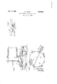
- Fig. 1 is a sectional elevation of one embodiment of the invention
- Fig. 2 is a plan view of the table and its drive, most of the perforated table or grate being broken away
- Fig. 3 is an elevation of a detail showing a modified construction for effecting the up and down motion of the table.
- Fig. 1 shows how the cooler is connected to the rotary kiln in cross-sectional elevation.
- I is the lower end of the rotary kiln, for instance for burning of Portland cement.
- 2 is the kiln hood. 3 is the burner, or pipe through which the fuel is injected into the kiln.
- a funnel shaped cover 4 below which is the round table, or round pan, clinker cooler 5.
- the supports of the kiln and its hood are not shown on the drawing to avoid confusion.
- the clinker is falling on the center of the round table or pan cooler and is covering it with a layer, for instance, a few inches thick. It is kept moving to the periphery of the table by means to be described later, while the cooling air is forced from the wind box 6 through the perforated top 1 of the table or pan and through the layer of clinker 8.
- the cooled clinker is discharged by suitable means from the edge of the table, for instance through an overflow. spout 9 (Fig. 2).
- the air is coming from a fan through pipe l2 into the wind box 6 and is passing through the hot central part of the clinker layer, is heated to high temperature and is moving through the channel It into the kiln.
- the heat of hot clinker is salvaged for the burning process.
- more air is pressed through the clinker than is required for combustion of fuel.
- This excess air heated to a low temperature near the periphery of the pan may be utilized partly as primary air for combustion, or for other purposes. Or it may go to waste on account of its very low temperature and heat content.
- FIGs 1 and 2 show one shape of the apparatus which has been found practical and eflicient. It consists essentially 10 of a double bottom pan mounted on inclined flexible legs ll. Fig. 2 shows, for instance, 4 legs (II) of the pan. On the elevation Fig. 1 only one of the legs is drawn out to avoid confusion in the drawing.
- the upper bottom I is a grate made, for instance, of perforated metal, or narrowly spaced grate bars for air passage.
- the compressed air for cooling is entering through pipe l2.
- the grate may be flat or slightly cupped in the middle.
- the hot material in the center is thinner, and the cooler material near the edges of the pan is thicker. By this means the air fiow through the entire area of the pan 2 may be equalized.
- the flexible and springy inclined legs II are attached in such a way that the pan can have only a tangential, or annular shaking movement around its stationary center as indicated by arrows 30 on Fig. 2.
- a radial movement is hindered.
- the pan is shaken or vibrated in the mentioned movement with a frequency which may be from a few strokes per minute up to the frequencies as employed in the alternating electrical current.
- the stroke of the movement on the edge of the pan may vary from 1/64 of an inch to a few inches. The higher the frequency of the shaking, or vibration, the smaller needs to be the stroke. I have discovered that shaking. the pan in this way the material in it begins to rotate in a fairly regular motion around the center, as indicated by arrow 3
- FIG. 3 shows for instance another way of reaching the same effect.
- 32 indicates the pan,.which is supported on a number of rollers 33 along the edge of the pan.
- Therollers rest on inclined elements 34.
- C011 springs 35 of suitable strength fastened between the shaking .table and the stationary support facilitate the'shaking.
- the shaking of the table in tangential motion may be obtained by different means or methods.
- a rotating, horizontal shaft l3 (Fig. 2) may be attached to the pan through its center with bearings II in the side walls of the pan.
- eccentric weights I! (Fig. 2) are fastened to the shaft and are ofiset under 180 degrees to each other.
- the shaft is rotated through motor l6, speed reducer l1 and flexible coupling l8. Due to centrifugal forces of the eccentric weights the pan is shaken .in an angular or tangential motion.
- the table could be shaken also for instance by reciprocating pushers, fastened to eccentrics on a rotating shaft, or directly by electrcmagnets as employed in vibrating screens.
- the table may be subdivided into a discshaped central part and into a ring-shaped part adJacent to the central part.- Both parts could be shaken separately in order to obtain a more uniform linear stroke on the entire area of the table.
- the described methods of moving the material to be submitted to heat exchange on a table or pan do not preclude other methods or means in order to accomplish the same task.
- the flexibly supported' table may be shaken in a sieving motion in a horizontal plane, so that each point of it, including the center, will describe a small circle; or it may be supported by vertical springs and shaken up and down, or any kind of combined motion between the three different shaking motions may be applied.
- the table or pan may be charged on the periphery and discharged centrally.
- the apparatus described is not restricted to the cooling of cement clinker. It may be used for any material, for instance burned lime, dolomite, sintered flue dust of blast furnaces, calcined hot ores, chemical products, or any other gas permeable material.
- the apparatus described does not serve only for cooling the mentioned materials, but at the sametimeitisalsoaveryeflicientheatexchanger between the heat in the hot material andthe cooling gas.
- Thisheatmaybetransferred with up to ei'llciency and the hot gas may be utilized for combustion purposes, for 5 dryin the materials, or any heating purpose.
- the pan or table is not restricted to the round shape, which form, however, is preferable. Oval, square, polygonal or ring shaped tables or pans m could be used.
- the method of cooling hot granular material and obtaining heat therefrom consisting in forming a substantially circular bed of the mate- 16 rial with portions at the same distance from the center of the same thickness, oscillating the bed to cause each particle thereof to travel in a spiral path, supplying material at one end of the path, discharging it at the other, blowing air through the bed throughout its area and utilizing the exit air heated by its passage through the bed.
- Apparatus for cooling hot granular solid material and obtaining heat therefrom comprising, in combination, a convex substantially circular foraminous table mounted to oscillate 30 about a vertical axis and having an upstanding peripheral flange provided with an overflow spout, a disk like hood disposed over said table and slightly spaced from the top surface of material on the table, said disk having a central a5 aperture through which material is fed to said table, means to oscillate said table to cause particles of material thereon to travel in a spiral path, and means toblow air through the perforations in said table and material thereon. 4o
- Apparatus for cooling solid granular material and obtaining heat therefrom comprising, in combination, a substantially foraminous circular table, means to supply material to be cooled to the center of said table, means to maintain portions of said material on the table at the same distance from the center of the same thickness, means to oscillate said table to advance the particles of material on the table step by step in a spiral path from the central part of the table 50 to its periphery, and means to blow air through the perforations in the table and the material thereon.
- Apparatus-in accordance with claim 4 with means to give'the table an up and down move- 55 ment during each oscillation.
Landscapes
- Engineering & Computer Science (AREA)
- Mechanical Engineering (AREA)
- General Engineering & Computer Science (AREA)
- Furnace Details (AREA)
Description
Dec. 17, 1935. o. LELLEP HEAT EXCHANGER AND CLINKER COOLER Filed Jan. 12, 1934' Patented Dec. 17, 1935 UNITED STATES PATENT OFFICE- 2,024,934 HEAT EXCHANGER AND 01.1mm]: oooLEa Otto Lellep, New York, N. Y. Application January 12, 1934, Serial No. 706,432
' Claims. (01. 34-38) This invention consists in an improved heat exchanger between gas permeable solids and gas. Its main application is in connection with rotary kilns .for burning of Portland cement, particularly for cooling clinker with air. It is of the so called air quench type in which clinker is cooled rapidly by forcing compressed air through a layer of hot clinkers.
A number of clinker coolers of the air-quench type has appeared on the market in recent years. The advantages of my invention consist in its compactness, efliciency and particularly low cost of installation in comparison with known clinker coolers.
Fig. 1 is a sectional elevation of one embodiment of the invention, Fig. 2 is a plan view of the table and its drive, most of the perforated table or grate being broken away, and Fig. 3 is an elevation of a detail showing a modified construction for effecting the up and down motion of the table.
Fig. 1 shows how the cooler is connected to the rotary kiln in cross-sectional elevation. I is the lower end of the rotary kiln, for instance for burning of Portland cement. 2 is the kiln hood. 3 is the burner, or pipe through which the fuel is injected into the kiln. To the lower end of the hood is suspended a funnel shaped cover 4, below which is the round table, or round pan, clinker cooler 5. The supports of the kiln and its hood are not shown on the drawing to avoid confusion. The clinker is falling on the center of the round table or pan cooler and is covering it with a layer, for instance, a few inches thick. It is kept moving to the periphery of the table by means to be described later, while the cooling air is forced from the wind box 6 through the perforated top 1 of the table or pan and through the layer of clinker 8.
The cooled clinker is discharged by suitable means from the edge of the table, for instance through an overflow. spout 9 (Fig. 2). The air is coming from a fan through pipe l2 into the wind box 6 and is passing through the hot central part of the clinker layer, is heated to high temperature and is moving through the channel It into the kiln. Thus the heat of hot clinker is salvaged for the burning process. Usually more air is pressed through the clinker than is required for combustion of fuel. This excess air heated to a low temperature near the periphery of the pan may be utilized partly as primary air for combustion, or for other purposes. Or it may go to waste on account of its very low temperature and heat content.
The movement of clinker or hot furnace product from the center to the edge of round table may be obtained by different means and methods. For thermal and mechanical efficiency of the apparatus it is desirable that the 5 thickness of material at equal distances from the center be equal and that the movement of material be regular. Figures 1 and 2 show one shape of the apparatus which has been found practical and eflicient. It consists essentially 10 of a double bottom pan mounted on inclined flexible legs ll. Fig. 2 shows, for instance, 4 legs (II) of the pan. On the elevation Fig. 1 only one of the legs is drawn out to avoid confusion in the drawing. The upper bottom I is a grate made, for instance, of perforated metal, or narrowly spaced grate bars for air passage.
It is covered by a layer of clinker or material 8,
to be cooled. The compressed air for cooling is entering through pipe l2. The grate may be flat or slightly cupped in the middle.
Through cupping, the hot material in the center is thinner, and the cooler material near the edges of the pan is thicker. By this means the air fiow through the entire area of the pan 2 may be equalized.
The flexible and springy inclined legs II are attached in such a way that the pan can have only a tangential, or annular shaking movement around its stationary center as indicated by arrows 30 on Fig. 2. A radial movement is hindered. By suitable means the pan is shaken or vibrated in the mentioned movement with a frequency which may be from a few strokes per minute up to the frequencies as employed in the alternating electrical current. The stroke of the movement on the edge of the pan may vary from 1/64 of an inch to a few inches. The higher the frequency of the shaking, or vibration, the smaller needs to be the stroke. I have discovered that shaking. the pan in this way the material in it begins to rotate in a fairly regular motion around the center, as indicated by arrow 3| (Fig. 2). This peculiar movement of the material in the shaking pan is caused by the fact that during each stroke of the shaking movement each particle of the material is thrown in an inclined direction upward and tangentially forward as indicated by arrow 3|. In case the pan is operated continuously, charging it centrally and discharging the material on the periphery any particle on the shaking pan is describing an almost regular spiral movement. Shaking motion keeps the material. to be cooled in motion and thus facilitates air e at a low energy cost.
1 Round or spiral motion of the material is caused by the inclination of the flexible legs of the shaking table. This motion makes the layer of material uniform andv submits each particle to a fairly uniform cooling time.
Support of the tangentially shaking pan is not restricted to the flexible springy legs I I. Fig. 3 shows for instance another way of reaching the same effect. 32 indicates the pan,.which is supported on a number of rollers 33 along the edge of the pan. Therollers rest on inclined elements 34. C011 springs 35 of suitable strength fastened between the shaking .table and the stationary support facilitate the'shaking.
The shaking of the table in tangential motion may be obtained by different means or methods. For instance a rotating, horizontal shaft l3 (Fig. 2) may be attached to the pan through its center with bearings II in the side walls of the pan. Near the periphery of the pan two eccentric weights I! (Fig. 2) are fastened to the shaft and are ofiset under 180 degrees to each other. The shaft is rotated through motor l6, speed reducer l1 and flexible coupling l8. Due to centrifugal forces of the eccentric weights the pan is shaken .in an angular or tangential motion. The table could be shaken also for instance by reciprocating pushers, fastened to eccentrics on a rotating shaft, or directly by electrcmagnets as employed in vibrating screens.
The table may be subdivided into a discshaped central part and into a ring-shaped part adJacent to the central part.- Both parts could be shaken separately in order to obtain a more uniform linear stroke on the entire area of the table.
The described methods of moving the material to be submitted to heat exchange on a table or pan do not preclude other methods or means in order to accomplish the same task. For instance, the flexibly supported' table may be shaken in a sieving motion in a horizontal plane, so that each point of it, including the center, will describe a small circle; or it may be supported by vertical springs and shaken up and down, or any kind of combined motion between the three different shaking motions may be applied. The table or pan may be charged on the periphery and discharged centrally.
The apparatus described is not restricted to the cooling of cement clinker. It may be used for any material, for instance burned lime, dolomite, sintered flue dust of blast furnaces, calcined hot ores, chemical products, or any other gas permeable material.
The apparatus described does not serve only for cooling the mentioned materials, but at the sametimeitisalsoaveryeflicientheatexchanger between the heat in the hot material andthe cooling gas. Thisheatmaybetransferred with up to ei'llciency and the hot gas may be utilized for combustion purposes, for 5 dryin the materials, or any heating purpose.
The pan or table is not restricted to the round shape, which form, however, is preferable. Oval, square, polygonal or ring shaped tables or pans m could be used.
I claim:
1. The method of cooling hot granular material and obtaining heat therefrom consisting in forming a substantially circular bed of the mate- 16 rial with portions at the same distance from the center of the same thickness, oscillating the bed to cause each particle thereof to travel in a spiral path, supplying material at one end of the path, discharging it at the other, blowing air through the bed throughout its area and utilizing the exit air heated by its passage through the bed.
2. The method according to claim 1 wherein the bed of material is formed with its upper surface flat and horizontal and its lower surface 25 concave.
3. Apparatus for cooling hot granular solid material and obtaining heat therefrom comprising, in combination, a convex substantially circular foraminous table mounted to oscillate 30 about a vertical axis and having an upstanding peripheral flange provided with an overflow spout, a disk like hood disposed over said table and slightly spaced from the top surface of material on the table, said disk having a central a5 aperture through which material is fed to said table, means to oscillate said table to cause particles of material thereon to travel in a spiral path, and means toblow air through the perforations in said table and material thereon. 4o
4. Apparatus for cooling solid granular material and obtaining heat therefrom, comprising, in combination, a substantially foraminous circular table, means to supply material to be cooled to the center of said table, means to maintain portions of said material on the table at the same distance from the center of the same thickness, means to oscillate said table to advance the particles of material on the table step by step in a spiral path from the central part of the table 50 to its periphery, and means to blow air through the perforations in the table and the material thereon.
5. Apparatus-in accordance with claim 4 with means to give'the table an up and down move- 55 ment during each oscillation.
O'I'I'OLEILEP.
Priority Applications (1)
| Application Number | Priority Date | Filing Date | Title |
|---|---|---|---|
| US706432A US2024934A (en) | 1934-01-12 | 1934-01-12 | Heat exchanger and clinker cooler |
Applications Claiming Priority (1)
| Application Number | Priority Date | Filing Date | Title |
|---|---|---|---|
| US706432A US2024934A (en) | 1934-01-12 | 1934-01-12 | Heat exchanger and clinker cooler |
Publications (1)
| Publication Number | Publication Date |
|---|---|
| US2024934A true US2024934A (en) | 1935-12-17 |
Family
ID=24837537
Family Applications (1)
| Application Number | Title | Priority Date | Filing Date |
|---|---|---|---|
| US706432A Expired - Lifetime US2024934A (en) | 1934-01-12 | 1934-01-12 | Heat exchanger and clinker cooler |
Country Status (1)
| Country | Link |
|---|---|
| US (1) | US2024934A (en) |
Cited By (4)
| Publication number | Priority date | Publication date | Assignee | Title |
|---|---|---|---|---|
| US2480727A (en) * | 1944-01-22 | 1949-08-30 | Kaiser Company Inc | Method for cooling |
| US2543776A (en) * | 1944-05-13 | 1951-03-06 | Allis Chalmers Mfg Co | Apparatus for cooling granular solids |
| US2598931A (en) * | 1950-03-14 | 1952-06-03 | Fuller Co | Clinker cooler |
| US2972197A (en) * | 1954-07-19 | 1961-02-21 | Rice Growers Ass Of California | Continuous vibratory heating apparatus |
-
1934
- 1934-01-12 US US706432A patent/US2024934A/en not_active Expired - Lifetime
Cited By (4)
| Publication number | Priority date | Publication date | Assignee | Title |
|---|---|---|---|---|
| US2480727A (en) * | 1944-01-22 | 1949-08-30 | Kaiser Company Inc | Method for cooling |
| US2543776A (en) * | 1944-05-13 | 1951-03-06 | Allis Chalmers Mfg Co | Apparatus for cooling granular solids |
| US2598931A (en) * | 1950-03-14 | 1952-06-03 | Fuller Co | Clinker cooler |
| US2972197A (en) * | 1954-07-19 | 1961-02-21 | Rice Growers Ass Of California | Continuous vibratory heating apparatus |
Similar Documents
| Publication | Publication Date | Title |
|---|---|---|
| US2668041A (en) | Heat treatment of finely divided solids | |
| US2024934A (en) | Heat exchanger and clinker cooler | |
| JP2019005703A (en) | Cooling apparatus of fly ash | |
| US4728471A (en) | Treatment of expansible materials to form lightweight aggregate | |
| US2861356A (en) | Apparatus for cooling granular materials | |
| US3022988A (en) | Material treating device | |
| US3763011A (en) | Rotary hearth calciner having stationary soaking pit | |
| US1185136A (en) | Apparatus for burning cement and recovering the resulting dust. | |
| GB2153055A (en) | Process and installation for the thermal treatment of granular materials | |
| US4094630A (en) | Welding flux curing apparatus | |
| US2055940A (en) | Clinker cooler | |
| US3274701A (en) | Stationary circular contact cooler for calcined lime and other materials | |
| JPH08189767A (en) | Continuous drying or roasting apparatus | |
| US3766663A (en) | Preheater for lime kiln | |
| US2489211A (en) | Apparatus for producing cement clinker and the like | |
| JPH06206746A (en) | High temperature fired product cooling device | |
| US2822078A (en) | Cooling device | |
| US2471882A (en) | Means for converting material | |
| SU972203A1 (en) | Apparatus for preheating and partly calcinating lump material | |
| US2891321A (en) | Apparatus for cooling cement clinkers | |
| JP3873367B2 (en) | Operation method of mobile hearth furnace | |
| USRE30469E (en) | Preheater for lime kiln | |
| US2793020A (en) | Method and apparatus for supplying a kiln with a uniform flow of secondary combustion air at a constant temperature | |
| JPS6244786Y2 (en) | ||
| RU2618585C2 (en) | Method of finely-divided bulk materials high heat treatment and device for its implementation |