US2024930A - Plumbing fixture - Google Patents
Plumbing fixture Download PDFInfo
- Publication number
- US2024930A US2024930A US35780A US3578035A US2024930A US 2024930 A US2024930 A US 2024930A US 35780 A US35780 A US 35780A US 3578035 A US3578035 A US 3578035A US 2024930 A US2024930 A US 2024930A
- Authority
- US
- United States
- Prior art keywords
- receptacle
- conduit
- head
- discharge head
- joint member
- Prior art date
- Legal status (The legal status is an assumption and is not a legal conclusion. Google has not performed a legal analysis and makes no representation as to the accuracy of the status listed.)
- Expired - Lifetime
Links
- 238000009428 plumbing Methods 0.000 title description 15
- XLYOFNOQVPJJNP-UHFFFAOYSA-N water Substances O XLYOFNOQVPJJNP-UHFFFAOYSA-N 0.000 description 13
- 239000007921 spray Substances 0.000 description 7
- 238000010276 construction Methods 0.000 description 5
- 230000000295 complement effect Effects 0.000 description 2
- 238000004519 manufacturing process Methods 0.000 description 2
- 230000001105 regulatory effect Effects 0.000 description 2
- 238000003287 bathing Methods 0.000 description 1
- 150000001768 cations Chemical class 0.000 description 1
- 210000004907 gland Anatomy 0.000 description 1
- 238000009434 installation Methods 0.000 description 1
- 238000012986 modification Methods 0.000 description 1
- 230000004048 modification Effects 0.000 description 1
- 238000007789 sealing Methods 0.000 description 1
- 239000007787 solid Substances 0.000 description 1
- 238000005406 washing Methods 0.000 description 1
Images
Classifications
-
- E—FIXED CONSTRUCTIONS
- E03—WATER SUPPLY; SEWERAGE
- E03C—DOMESTIC PLUMBING INSTALLATIONS FOR FRESH WATER OR WASTE WATER; SINKS
- E03C1/00—Domestic plumbing installations for fresh water or waste water; Sinks
- E03C1/02—Plumbing installations for fresh water
- E03C1/06—Devices for suspending or supporting the supply pipe or supply hose of a shower-bath
Definitions
- the present invention relates in general to improvements in plumbing iixtures, and relates more specifically to an adjustable fixture for wash receptacles.
- a general object of the invention is to provide a unitary, adjustable plumbing fixture mounted adjacent a tub or receptacle and adjustable to position the discharge head at a considerable elevation above the receptacle, or within or adjacent the receptacle, or positionable throughout a range between said limits, the device serving the purpose of multiple xtures and requiring but a single set of control valves (or a mixing valve).
- a further object of the invention is to provide a xture of the character described in which the discharge head is universally adjustable for directing the discharge therefrom in various directions relative to the receptacle, and in which the head may be arranged for manipulation to convert the discharge from a stream or jet to a spray, and viceversa.
- the present invention is not concerned with the problem of back-siphoning and aims at the provision of a fixture which permits the discharge head to be brought down into the confines of the receptacle for a wide range of adjustment including directing the same upwardly or horizontally.
- Another specific object of the invention is to provide a unitary adjustable fixture for wash receptacles wherein the head is adjustably carried by the outer end of an adjustably mounted, sectional conduit in which the sections of the conduit are also adjustably joined, whereby the entire fixture is susceptible of being adjusted and disposed relative to the receptacle in a great many positions and at various elevations, to suit the position and convenience of the user'.
- Still another object of the invention is to provide a plumbing fixture which can be adjusted and manipulated very simply and rapidly with- 5 out the use of tools.
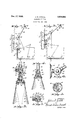
- Fig. 1 is a fragmentary sectional view through 2 a bathtub and adjoining wall and floor portions and showing the improved fixture installed, at its inner end, within the tub, there being broken line showings of various positions of adjustment of the fixture; 30
- Fig. 2 is a similar view only showing the inner end of the iixture installed above the tub;
- Fig. 3 is an enlarged sectional view through the upper or outer joint member and the discharge head, with the regulating disc in one po- 35 sition of adjustment and showing the resulting form of the discharged spray of water;
- Fig. 4 is an enlarged sectional View of a modified form of upper or outer joint member and a modified form of discharge head associated 40 therewith;
- Fig. 5 is an end view of the discharge head of Fig. 3 with a portion of the disc broken away;
- Fig. 6 is an enlarged side View of the inner joint member and the mounting plate therefor; 45 and Fig. 7 is a transverse sectional view taken on line 1-1 of Fig. 3.
- Hot and cold water pipes I3 and I4 shown schematically, extend from a source (not shown) and are concealed rearwardly of the wall 9, and within said pipes are hot and cold water control valvesV I5 and I6 operated by valve rods and handles I1 and I8 projecting exteriorly of the wall 9 a suitable distance above the tub.
- a conventional form of mixing valve may be used, if desired.
- the hot and cold water pipes merge into a single pipe I9 which is extended through the wall.
- Fig. 1 said pipe is extended through the wall portion I9 and through the end of the tub. It may be inconvenient to extend said pipe through the tub and
- Fig. 2 illustrates an arrangement wherein the pipe I9l is extended through the wall portion 9 immediately Vabove the tub.
- a bracket plate 29 embraces the outwardly projecting portion of the pipe I9, and said plate is secured to the outer surface of the wall 9.
- V The bracket plate carries a lower knuckle joint member designated generally by thenumeral 2I.
- Said'knuckle joint member is similar in construction to other knuckle joint members 22 and 22 used in the assembly, one being shown in detail in Figs. 3 and 7 and to be described fully hereinafter.
- the term knuckle joint as used herein and in the claims, is intended to cover any joint which allows relative angular movement between adjacent portions of two pipe or g conduit sections, or between a pipe or conduit section and an adjacent structure.
- the joint member 2l is composed of two relatively movable sections having flat engaging surfaces and pivotally held together by a pin 23.
- connection 25 Adapted to connect and coact with the tubular connection 25 is another elongated rigid, tubular connection 25.
- the inner end portion of this connection is threaded into a boss 25 also Von the joint member 22, the connection 25 and the boss being in commurn'cation with the reservoir portion oi the joint member 22 for water passage purposes.
- this structure forms a two-section jointed conduit. The entire conduit may be moved orgadjusted on the joint member 2I and the outer conduit section 26 may also be moved or adjusted on the joint member 22 and relative to the conduit section 25.
- connection or conduit section 26 is threaded into a boss 21 on the joint member 22.
- the joint member 22 includes a substantially semi-spherical section 28 which is integral with the boss 2?.
- Said section 28 has a fiat face which is in engagement with a flat surface on a complementary semi-spherical section Y 29, the latter section having an integral, externally threaded stem 39 provided with an interior duct 3
- There is a pair of ducts 32 in the section 29 establishing communication with the tubular member 29, at one end; and said ducts, at their other ends, open into a chamber 33 in said section 28.
- Said chamber is complementary to a smaller chamber 34 in the section 29 which communicates with the inner end of the duct 3I.
- the sections 23 and 29 are pivotally held together by a pivot pin 35 extended through a central portion of the section 29 and threaded 1o into a portion of the section 28.
- a tension spring 31 Within a recess 36 in the section 29 and surrounding a portion of the pin 35 there is a tension spring 31.
- the spring is seated against the inner face of an adjustment cap 3B on the outer end of the 15 pin, and said cap may be turned in either direction to vary the tension of said spring.
- the joint member 22' may be exactly similar in construction to the joint members 2
- a spray-spout or discharge head indi- 30 Threaded onto the outer end portion of the stem 39 is a spray-spout or discharge head indi- 30 cated generally by the numeral 40.
- Said discharge head is similar in construction and operation to that shown and described in co-pending application Serial #27,957, led June 22, 1935.
- the disc 4I in said head may be manipulated 35 to cause water toi be discharged in the form of an annular, diverging shower spray, or in the form of a substantially solid jet or stream, as
- Fig. 4 a slight modication is illustrated. 40
- the outer end portion of the conduit section 26 has secured therein a cylindrical Vportion of a ball member 42.
- the ball member has a port 43 therethrough establishing communication between the member 26 and the inner chamber 44 4-5 of a discharge head 49.
- the head is substantially universally movable on the Yball 42 and relative to the member 25 and is adjustably held on said ball by a gland 45 and a ring 46 engaging different portions of the ball member 50 and in threaded engagement with internal, inner end portions of the discharge head.
- the discharge head 49 is of the type shown and described in U. S. Patent #2,011,446, and by ma nipulation of a disc 4I' the form of the dis- 5.3 charged water can be regulated.
- the joint member 2I permits movement of the conduit section 25 relative to the' support
- the joint member 22 permits movement of the conduit section 26 relative to the section 60
- the joint member 22' (or the form of joint shown in Fig. 4) permits movement of the head member relative to the conduit section 23.
- the flow of water through the apparatus is as follows: Assuming that both of the valves I5 and I6 are opened, water flows from the pipes I3 and I4 into the pipe I9 and mixes therein, as well as in the subsequent connections. From the pipe I9 the Water flows through the joint member 2
- the device With the improved apparatus installed as shown, a minimum of fittings and parts are required and they are conveniently located relative to the tub or receptacle.
- the sectional and jointed conduit provides for a great range and variety of positions for the discharge head for various purposes. If the device is to be used as a shower bath it may be adjusted similarly to the full line showings in the drawing and may be disposed or swung to the proper elevation for the person using the apparatus. For shampooing or showering other portions of the body, the device may be manipulated to other intermediate positions. A person may stand in the receptacle or be seated exteriorly of the receptacle and lean over the same.
- the discharge head within the lower portion of the receptacle for directing a jet or spray upwardly relative to a person seated in the receptacle.
- the device With the conduit section 25 turned upwardly and the conduit section 26 turned downwardly, the device may be used to lill, rinse or flush out the receptacle, and for these purposes the head may be moved around on its joint member.
- the apparatus is of particular advantage and is inexpensive to manufacture and install in that it eliminates one complete set of valves and spout necessary in the former combination spray and spout installation.
- the adjustability of the twopart-conduit relative to the support, and the adjustability of the conduit sections relative to one another and the head relative to the conduit gives a wide range of movement and many convenient dispositions for multiple bathing and washing purposes. While the improved plumbing fixture has been shown and described herein as being specically applied to a receptacle in the form of a bathtub, it is the intent to have that term whenever employed herein, cover other types of wash receptacles. The entire structure is unique and attractive in appearance, may be very easily and conveniently adjusted and manipulated, and has demonstrated its practicability in actual use.
- a plumbing fixture comprising a support adjacent a receptacle, a discharge head, and an elongated, sectional conduit between the head and the support and pivotally connected to the latter, the discharge head and the outer end of the conduit being swingable from an elevated position over the receptacle and remote therefrom to a position within the receptacle.
- a plumbing iixture comprising a support adjacent a receptacle, a discharge head, and an elongated, sectional conduit between the head and the support and pivotally' connected to the latter, the sections of the conduit being rigid, the discharge head and the outer end of the conduit being swingable from an elevated position over the receptacle and remote therefrom to a position within the receptacle.
- a plumbing fixture comprising a support adjacent a receptacle, a discharge head, and an elongated, sectional conduit between the head and the support and pivotally connected to the latter, the sections of theconduit being rigid and connected by joint members permitting pivotal movement of one conduit section relative to the adjacent section, the discharge head and the outer end of the conduit being swingable from an elevated position over the receptacle and remote therefrom to a position within the receptacle.
- a plumbing fixture comprising a support adjacent a receptacle, a discharge head, and elongated movable and intermediately jointed means for supporting said head for disposition throughout a range, one limit point of which is considerably above and the other limit point of which is within the receptacle, said jointed means being pivotally connected to the support.
- a plumbing fixture comprising a support adjacent a receptacle, a discharge head, -and elongated movable means for supporting said head for disposition throughout a range, one limit point of which is considerably above and the other limit point of which is directly adjacent the receptacle, said elongated means being formed of rigid conduit sections, and joint means between adjacentiends of said sections, said elongated means being pivotally connected at its inner end. to said support.
- a plumbing fixture comprising an elongated tubular member formed of rigid sections movably connected together and movably supported at one end adjacent a receptacle, and a discharge head movably carried by the other end portion of the tubular member, the elongated member being movable and bendable to position the discharge head throughout a range, one limit point of which is consideraly above and the other limit point of which is directly adjacent a receptacle.
- a plumbing Xture comprising a support adjacent a receptacle, a discharge head, and an elongated conduit between the head and the support and pivotally connected to both of the same, the conduit being formed of a pair of pivotally connected sections, the head and the outer conduit section being swingable throughout a plane longitudinally of the receptacle from an elevated position over the receptacle and remote therefrom to a position directly adjacent the receptacle.
- a plumbing xture comprising a support adjacent a receptacle, a discharge head, and an elongated conduit between the head and the support and pivotally connected to both of the same, the conduit being formed of a pair of pivotally connected sections, the head and the outer conduit section or the head and both conduit sections being swingable throughout a plane longitudinally of the receptacle to dispose the head above the receptacle and remote therefrom, within the receptacle, or in intermediate positions between said limits.
- a plumbing fixture comprising a joint member mounted on a support adjacent a wash receptacle, another joint member pivotally carrying a discharge nozzle, a pair of elongated rigid conduit members interposed between said joint members, and another joint member interposed between the adjacent ends ofA said conduit members, the innermost conduit member being movable on its joint member relative to said support.
Landscapes
- Health & Medical Sciences (AREA)
- Life Sciences & Earth Sciences (AREA)
- Engineering & Computer Science (AREA)
- Hydrology & Water Resources (AREA)
- Public Health (AREA)
- Water Supply & Treatment (AREA)
- Nozzles (AREA)
Description
Dec. 17, 1935. .J. s. JUDELI.
PLUMBING FIXTURE Filed Aug.
ATTORNEY Patented Dec. 17, 1935 UNITED STATES PATENT OFFICE PLUIVIBING FIXTURE Application August 12, 1935, Serial No. 35,780 9 claims.` (o1. 4-148) The present invention relates in general to improvements in plumbing iixtures, and relates more specifically to an adjustable fixture for wash receptacles.
A general object of the invention is to provide a unitary, adjustable plumbing fixture mounted adjacent a tub or receptacle and adjustable to position the discharge head at a considerable elevation above the receptacle, or within or adjacent the receptacle, or positionable throughout a range between said limits, the device serving the purpose of multiple xtures and requiring but a single set of control valves (or a mixing valve).
A further object of the invention is to provide a xture of the character described in which the discharge head is universally adjustable for directing the discharge therefrom in various directions relative to the receptacle, and in which the head may be arranged for manipulation to convert the discharge from a stream or jet to a spray, and viceversa.
In co-pending applications Serials #27,957, liiled June 22, 1935, and 1,754, filed January 1, 1935, issued August 13, 1935, as patent #2,011,- 446, there are disclosed fixtures of the same general type as in the present invention, only said prior fixtures were designed to meet requirements against back-siphoning, which necessitated the location, or limited the disposition of the discharge heads to a position above the top of the tub or receptacle. These prior fixtures could not, therefore, be set with the discharge head or nozzle within the receptacle for the purpose of directing the jet or spray upwardly relative to the body of a person seated within the receptacle. Said prior fixtures, therefore, conned movement of the head to the longitudinal plane of the receptacle, because the head was of necessity kept above the receptacle walls.
The present invention is not concerned with the problem of back-siphoning and aims at the provision of a fixture which permits the discharge head to be brought down into the confines of the receptacle for a wide range of adjustment including directing the same upwardly or horizontally.
Another specific object of the invention is to provide a unitary adjustable fixture for wash receptacles wherein the head is adjustably carried by the outer end of an adjustably mounted, sectional conduit in which the sections of the conduit are also adjustably joined, whereby the entire fixture is susceptible of being adjusted and disposed relative to the receptacle in a great many positions and at various elevations, to suit the position and convenience of the user'.
Still another object of the invention is to provide a plumbing fixture which can be adjusted and manipulated very simply and rapidly with- 5 out the use of tools.
Other specific objects of the invention are to provide an adjustable, multiple-purpose fixture of the character described which is simple in construction, which may be conveniently in- 10 stalled, assembled, or dismantled, which is inexpensive to manufacture, and which is highly effective and efficient in operation.
The above and other objects and advantages will be apparent from the following detailed de- 15 scription.
A clear conception of the several embodiments of the improvement and of the mode of constructing, manipulating and operating devices constructed in accordance therewith may be had 20 by referring to the drawing accompanying and forming a part of this specification, in which like reference characters designate the same o1' similar parts in the various views.
Fig. 1 is a fragmentary sectional view through 2 a bathtub and adjoining wall and floor portions and showing the improved fixture installed, at its inner end, within the tub, there being broken line showings of various positions of adjustment of the fixture; 30
Fig. 2 is a similar view only showing the inner end of the iixture installed above the tub;
Fig. 3 is an enlarged sectional view through the upper or outer joint member and the discharge head, with the regulating disc in one po- 35 sition of adjustment and showing the resulting form of the discharged spray of water;
Fig. 4 is an enlarged sectional View of a modified form of upper or outer joint member and a modified form of discharge head associated 40 therewith;
Fig. 5 is an end view of the discharge head of Fig. 3 with a portion of the disc broken away;
Fig. 6 is an enlarged side View of the inner joint member and the mounting plate therefor; 45 and Fig. 7 is a transverse sectional view taken on line 1-1 of Fig. 3.
While the invention has been shown herein as being specifically applied to a bathtub, it will 50 be apparent that the novel features are more generally applicable to other types of receptacles, containers, sinks, and the like.
Referring now more particularly to the drawing, it will be apparent that by way of illustrationY the improved fixture is shown as beingV associated with a conventional bathtub 8, of the built-in type, and the adjoining end wall portions of the room wherein the tub is installed are represented by the numerals 9 and I9 respectively. The tub is provided with the usual bottom drain opening II. Hot and cold water pipes I3 and I4, shown schematically, extend from a source (not shown) and are concealed rearwardly of the wall 9, and within said pipes are hot and cold water control valvesV I5 and I6 operated by valve rods and handles I1 and I8 projecting exteriorly of the wall 9 a suitable distance above the tub. ln lieu of the separate Y valves and valve handles, it is obvious that a conventional form of mixing valve may be used, if desired. The hot and cold water pipes merge into a single pipe I9 which is extended through the wall. In Fig. 1 said pipe is extended through the wall portion I9 and through the end of the tub. It may be inconvenient to extend said pipe through the tub and Fig. 2 illustrates an arrangement wherein the pipe I9l is extended through the wall portion 9 immediately Vabove the tub. Y
A bracket plate 29 embraces the outwardly projecting portion of the pipe I9, and said plate is secured to the outer surface of the wall 9. VThe bracket plate carries a lower knuckle joint member designated generally by thenumeral 2I.
Said'knuckle joint member is similar in construction to other knuckle joint members 22 and 22 used in the assembly, one being shown in detail in Figs. 3 and 7 and to be described fully hereinafter. The term knuckle joint as used herein and in the claims, is intended to cover any joint which allows relative angular movement between adjacent portions of two pipe or g conduit sections, or between a pipe or conduit section and an adjacent structure. Suiiice it to say thatthe joint member 2l is composed of two relatively movable sections having flat engaging surfaces and pivotally held together by a pin 23. Ihe end of the pipe I9 which is embraced by the bracket plate 29 opens into a hollow reservoir Within the joint member 2I, and through certain ports water is discharged into a boss 24 into which is threaded the inner end portion of an elongated, rigid, tubularconnection 25. The other end portion of said connection 25 is threaded into a boss 24 on the joint member 22.
Adapted to connect and coact with the tubular connection 25 is another elongated rigid, tubular connection 25. The inner end portion of this connection is threaded into a boss 25 also Von the joint member 22, the connection 25 and the boss being in commurn'cation with the reservoir portion oi the joint member 22 for water passage purposes. Obviously this structure forms a two-section jointed conduit. The entire conduit may be moved orgadjusted on the joint member 2I and the outer conduit section 26 may also be moved or adjusted on the joint member 22 and relative to the conduit section 25. The
outer end portion of the connection or conduit section 26 is threaded into a boss 21 on the joint member 22. e
With special reference to Figs. 3 and 7, it will be observed that the joint member 22 includes a substantially semi-spherical section 28 which is integral with the boss 2?. Said section 28 has a fiat face which is in engagement with a flat surface on a complementary semi-spherical section Y 29, the latter section having an integral, externally threaded stem 39 provided with an interior duct 3|. There is a pair of ducts 32 in the section 29 establishing communication with the tubular member 29, at one end; and said ducts, at their other ends, open into a chamber 33 in said section 28. Said chamber is complementary to a smaller chamber 34 in the section 29 which communicates with the inner end of the duct 3I. The sections 23 and 29 are pivotally held together by a pivot pin 35 extended through a central portion of the section 29 and threaded 1o into a portion of the section 28. Within a recess 36 in the section 29 and surrounding a portion of the pin 35 there is a tension spring 31. The spring is seated against the inner face of an adjustment cap 3B on the outer end of the 15 pin, and said cap may be turned in either direction to vary the tension of said spring. Adjacent the meeting portions of the flat faces of the sections 28 and 29, disposed in suitable recesses, is a sealing ring or washer 39 to prevent leak- 2G age between said sections. As previously men-v tioned, the joint member 22', just described, may be exactly similar in construction to the joint members 2| and 22, the only difference being that the tension springs employed in the mem- 25 bers 2l and 22 may be of diierent degrees of strength and tension than that employed in the member 22.
Threaded onto the outer end portion of the stem 39 is a spray-spout or discharge head indi- 30 cated generally by the numeral 40. Said discharge head is similar in construction and operation to that shown and described in co-pending application Serial #27,957, led June 22, 1935. The disc 4I in said head may be manipulated 35 to cause water toi be discharged in the form of an annular, diverging shower spray, or in the form of a substantially solid jet or stream, as
desired. Y
In Fig. 4 a slight modication is illustrated. 40 The outer end portion of the conduit section 26 has secured therein a cylindrical Vportion of a ball member 42. The ball member has a port 43 therethrough establishing communication between the member 26 and the inner chamber 44 4-5 of a discharge head 49. The head is substantially universally movable on the Yball 42 and relative to the member 25 and is adjustably held on said ball by a gland 45 and a ring 46 engaging different portions of the ball member 50 and in threaded engagement with internal, inner end portions of the discharge head. The discharge head 49 is of the type shown and described in U. S. Patent #2,011,446, and by ma nipulation of a disc 4I' the form of the dis- 5.3 charged water can be regulated.
Obviously, the joint member 2I permits movement of the conduit section 25 relative to the' support, the joint member 22 permits movement of the conduit section 26 relative to the section 60 25, and the joint member 22' (or the form of joint shown in Fig. 4) permits movement of the head member relative to the conduit section 23. By this arrangement a great variety of positions of the apparatus may be attained, as appears 65 from the full and broken line showings in Figs. 1 and 2.
The flow of water through the apparatus is as follows: Assuming that both of the valves I5 and I6 are opened, water flows from the pipes I3 and I4 into the pipe I9 and mixes therein, as well as in the subsequent connections. From the pipe I9 the Water flows through the joint member 2| and into and through the conduit Section 25. At the outer end thereof the Water 75 passes through the joint member 22 and then into and through the conduit section 26. At the end of this conduit section the water passes through the outermost joint member and into and through the discharge head, from whence it is discharged as a spray or jet.
With the improved apparatus installed as shown, a minimum of fittings and parts are required and they are conveniently located relative to the tub or receptacle. The sectional and jointed conduit provides for a great range and variety of positions for the discharge head for various purposes. If the device is to be used as a shower bath it may be adjusted similarly to the full line showings in the drawing and may be disposed or swung to the proper elevation for the person using the apparatus. For shampooing or showering other portions of the body, the device may be manipulated to other intermediate positions. A person may stand in the receptacle or be seated exteriorly of the receptacle and lean over the same. It is also possible, as illustrated in broken lines, to position the discharge head within the lower portion of the receptacle for directing a jet or spray upwardly relative to a person seated in the receptacle. With the conduit section 25 turned upwardly and the conduit section 26 turned downwardly, the device may be used to lill, rinse or flush out the receptacle, and for these purposes the head may be moved around on its joint member.
The apparatus is of particular advantage and is inexpensive to manufacture and install in that it eliminates one complete set of valves and spout necessary in the former combination spray and spout installation. The adjustability of the twopart-conduit relative to the support, and the adjustability of the conduit sections relative to one another and the head relative to the conduit gives a wide range of movement and many convenient dispositions for multiple bathing and washing purposes. While the improved plumbing fixture has been shown and described herein as being specically applied to a receptacle in the form of a bathtub, it is the intent to have that term whenever employed herein, cover other types of wash receptacles. The entire structure is unique and attractive in appearance, may be very easily and conveniently adjusted and manipulated, and has demonstrated its practicability in actual use.
It should be understood that it is not desired to limit the present invention to the exact details of construction shown and described, for various modifications within the scope of the claims may occur to persons skilled in the art.
What is claimed as the invention is:-
l. A plumbing fixture, comprising a support adjacent a receptacle, a discharge head, and an elongated, sectional conduit between the head and the support and pivotally connected to the latter, the discharge head and the outer end of the conduit being swingable from an elevated position over the receptacle and remote therefrom to a position within the receptacle.
2. A plumbing iixture, comprising a support adjacent a receptacle, a discharge head, and an elongated, sectional conduit between the head and the support and pivotally' connected to the latter, the sections of the conduit being rigid, the discharge head and the outer end of the conduit being swingable from an elevated position over the receptacle and remote therefrom to a position within the receptacle.
3. A plumbing fixture, comprising a support adjacent a receptacle, a discharge head, and an elongated, sectional conduit between the head and the support and pivotally connected to the latter, the sections of theconduit being rigid and connected by joint members permitting pivotal movement of one conduit section relative to the adjacent section, the discharge head and the outer end of the conduit being swingable from an elevated position over the receptacle and remote therefrom to a position within the receptacle.
4. A plumbing fixture, comprising a support adjacent a receptacle, a discharge head, and elongated movable and intermediately jointed means for supporting said head for disposition throughout a range, one limit point of which is considerably above and the other limit point of which is within the receptacle, said jointed means being pivotally connected to the support.
5. A plumbing fixture, comprising a support adjacent a receptacle, a discharge head, -and elongated movable means for supporting said head for disposition throughout a range, one limit point of which is considerably above and the other limit point of which is directly adjacent the receptacle, said elongated means being formed of rigid conduit sections, and joint means between adjacentiends of said sections, said elongated means being pivotally connected at its inner end. to said support.
6. A plumbing fixture, comprising an elongated tubular member formed of rigid sections movably connected together and movably supported at one end adjacent a receptacle, and a discharge head movably carried by the other end portion of the tubular member, the elongated member being movable and bendable to position the discharge head throughout a range, one limit point of which is consideraly above and the other limit point of which is directly adjacent a receptacle.
7. A plumbing Xture, comprising a support adjacent a receptacle, a discharge head, and an elongated conduit between the head and the support and pivotally connected to both of the same, the conduit being formed of a pair of pivotally connected sections, the head and the outer conduit section being swingable throughout a plane longitudinally of the receptacle from an elevated position over the receptacle and remote therefrom to a position directly adjacent the receptacle.
8. A plumbing xture, comprising a support adjacent a receptacle, a discharge head, and an elongated conduit between the head and the support and pivotally connected to both of the same, the conduit being formed of a pair of pivotally connected sections, the head and the outer conduit section or the head and both conduit sections being swingable throughout a plane longitudinally of the receptacle to dispose the head above the receptacle and remote therefrom, within the receptacle, or in intermediate positions between said limits.
9. A plumbing fixture, comprising a joint member mounted on a support adjacent a wash receptacle, another joint member pivotally carrying a discharge nozzle, a pair of elongated rigid conduit members interposed between said joint members, and another joint member interposed between the adjacent ends ofA said conduit members, the innermost conduit member being movable on its joint member relative to said support.
Priority Applications (1)
| Application Number | Priority Date | Filing Date | Title |
|---|---|---|---|
| US35780A US2024930A (en) | 1935-08-12 | 1935-08-12 | Plumbing fixture |
Applications Claiming Priority (1)
| Application Number | Priority Date | Filing Date | Title |
|---|---|---|---|
| US35780A US2024930A (en) | 1935-08-12 | 1935-08-12 | Plumbing fixture |
Publications (1)
| Publication Number | Publication Date |
|---|---|
| US2024930A true US2024930A (en) | 1935-12-17 |
Family
ID=21884742
Family Applications (1)
| Application Number | Title | Priority Date | Filing Date |
|---|---|---|---|
| US35780A Expired - Lifetime US2024930A (en) | 1935-08-12 | 1935-08-12 | Plumbing fixture |
Country Status (1)
| Country | Link |
|---|---|
| US (1) | US2024930A (en) |
Cited By (79)
| Publication number | Priority date | Publication date | Assignee | Title |
|---|---|---|---|---|
| US2472030A (en) * | 1946-02-05 | 1949-05-31 | Ivar V Thulin | Bathtub shower bath appliance |
| DE1059309B (en) * | 1955-06-09 | 1959-06-11 | Jacques Muller | Liquid dispensing device, especially for gas stations |
| US3205522A (en) * | 1963-08-28 | 1965-09-14 | Karl P Then | Universally adjustable tool holder |
| US3206769A (en) * | 1963-08-26 | 1965-09-21 | American Sterilizer Co | Apparatus for rinsing bed pans |
| US3208774A (en) * | 1962-07-16 | 1965-09-28 | Adjustable Fixture Company | Lamp fixtures |
| US3409315A (en) * | 1966-05-17 | 1968-11-05 | Swivelier Company Inc | Swivel joint |
| US3736986A (en) * | 1971-07-28 | 1973-06-05 | Gen Fire Extinguisher Corp | Swivel assembly |
| US4084271A (en) * | 1977-01-12 | 1978-04-18 | Ginsberg Irwin L | Steam bath device for shower |
| US5146639A (en) * | 1990-09-10 | 1992-09-15 | Wilbur Krause | Combination bath, shower and bidet spout |
| FR2682037A1 (en) * | 1989-01-06 | 1993-04-09 | Marielle Jean | Massage shower with articulated support arm, especially for bath |
| US5398978A (en) * | 1993-12-02 | 1995-03-21 | Henlex Inc. | Adjustable coupling for linking conduits |
| US5865378A (en) * | 1997-01-10 | 1999-02-02 | Teledyne Industries, Inc. | Flexible shower arm assembly |
| USD406636S (en) * | 1998-01-06 | 1999-03-09 | Teledyne Industries, Inc. | Flexible shower arm |
| US6164570A (en) * | 1994-11-14 | 2000-12-26 | Water Pik, Inc. | Self-supporting reconfigurable hose |
| USD440641S1 (en) | 1997-01-10 | 2001-04-17 | Water Pik, Inc. | Flexible shower arm |
| US6442775B1 (en) * | 2000-09-27 | 2002-09-03 | Friedrich Grohe Ag & Co. Kg | Pivotal dual-head shower fixture |
| US20030150969A1 (en) * | 2002-01-24 | 2003-08-14 | Sam Zhadanov | Device for holding a hand-held showerhead and the like |
| US6626210B2 (en) | 2001-01-12 | 2003-09-30 | Water Pik, Inc. | Flexible arm assembly |
| US6641057B2 (en) | 2000-12-12 | 2003-11-04 | Water Pik, Inc. | Shower head assembly |
| WO2004106651A1 (en) * | 2003-06-03 | 2004-12-09 | Idrosystem S.R.L. | Height-adjustable showerhead |
| US20050055765A1 (en) * | 2003-09-15 | 2005-03-17 | Roland Lagasse | Non-rotatable joints for shower head |
| US20060059616A1 (en) * | 2002-12-13 | 2006-03-23 | Klaus Grohe | Shower support |
| USD527440S1 (en) | 2004-09-01 | 2006-08-29 | Water Pik, Inc. | Drenching shower head |
| USD528631S1 (en) | 2000-12-12 | 2006-09-19 | Water Pik, Inc. | Pan head shower head |
| USD529151S1 (en) | 2004-10-18 | 2006-09-26 | Water Pik, Inc. | Articulating shower arm |
| US7114666B2 (en) | 2002-12-10 | 2006-10-03 | Water Pik, Inc. | Dual massage shower head |
| USD533253S1 (en) | 2004-11-03 | 2006-12-05 | Water Pik, Inc. | Elliptical shower head |
| USD577099S1 (en) | 2006-11-29 | 2008-09-16 | Water Pik, Inc. | Showerhead assembly |
| USD577793S1 (en) | 2006-11-29 | 2008-09-30 | Water Pik, Inc. | Showerhead assembly |
| USD580012S1 (en) | 2007-12-20 | 2008-11-04 | Water Pik, Inc. | Showerhead |
| USD580513S1 (en) | 2007-12-20 | 2008-11-11 | Water Pik, Inc. | Hand shower |
| USD581014S1 (en) | 2007-12-20 | 2008-11-18 | Water Pik, Inc. | Hand shower |
| USD590048S1 (en) | 2007-12-20 | 2009-04-07 | Water Pik, Inc. | Hand shower |
| USD592278S1 (en) | 2007-12-20 | 2009-05-12 | Water Pik, Inc. | Showerhead |
| US7533906B2 (en) | 2003-10-14 | 2009-05-19 | Water Pik, Inc. | Rotatable and pivotable connector |
| USD600777S1 (en) | 2008-09-29 | 2009-09-22 | Water Pik, Inc. | Showerhead assembly |
| USD603935S1 (en) | 2007-12-20 | 2009-11-10 | Water Pik, Inc. | Hand shower |
| USD605731S1 (en) | 2007-12-26 | 2009-12-08 | Water Pik, Inc. | Bracket for hand shower |
| USD606623S1 (en) | 2008-09-29 | 2009-12-22 | Water Pik, Inc. | Hand shower |
| USD616061S1 (en) | 2008-09-29 | 2010-05-18 | Water Pik, Inc. | Showerhead assembly |
| US7740186B2 (en) | 2004-09-01 | 2010-06-22 | Water Pik, Inc. | Drenching shower head |
| USD618766S1 (en) | 2008-05-01 | 2010-06-29 | Water Pik, Inc. | Showerhead arm |
| US7770822B2 (en) | 2006-12-28 | 2010-08-10 | Water Pik, Inc. | Hand shower with an extendable handle |
| US7789326B2 (en) | 2006-12-29 | 2010-09-07 | Water Pik, Inc. | Handheld showerhead with mode control and method of selecting a handheld showerhead mode |
| USD624156S1 (en) | 2008-04-30 | 2010-09-21 | Water Pik, Inc. | Pivot ball attachment |
| USD625776S1 (en) | 2009-10-05 | 2010-10-19 | Water Pik, Inc. | Showerhead |
| US7905429B2 (en) | 2005-10-18 | 2011-03-15 | Water Pik, Inc. | Dispensing system and method for shower arm |
| US8020787B2 (en) | 2006-11-29 | 2011-09-20 | Water Pik, Inc. | Showerhead system |
| US8024822B2 (en) | 2004-06-14 | 2011-09-27 | Water Pik, Inc. | Articulating shower arm |
| US8028935B2 (en) | 2007-05-04 | 2011-10-04 | Water Pik, Inc. | Low flow showerhead and method of making same |
| USD673649S1 (en) | 2012-01-27 | 2013-01-01 | Water Pik, Inc. | Ring-shaped wall mount showerhead |
| US8348181B2 (en) | 2008-09-15 | 2013-01-08 | Water Pik, Inc. | Shower assembly with radial mode changer |
| USD674050S1 (en) | 2012-01-27 | 2013-01-08 | Water Pik, Inc. | Ring-shaped handheld showerhead |
| US8366024B2 (en) | 2006-12-28 | 2013-02-05 | Water Pik, Inc. | Low speed pulsating showerhead |
| USD692111S1 (en) | 2012-10-11 | 2013-10-22 | Water Pik, Inc. | Mounting bracket for water flosser |
| US8616470B2 (en) | 2010-08-25 | 2013-12-31 | Water Pik, Inc. | Mode control valve in showerhead connector |
| US8733675B2 (en) | 2006-04-20 | 2014-05-27 | Water Pik, Inc. | Converging spray showerhead |
| US8794543B2 (en) | 2006-12-28 | 2014-08-05 | Water Pik, Inc. | Low-speed pulsating showerhead |
| USD711505S1 (en) | 2013-05-20 | 2014-08-19 | Water Pik, Inc. | Shower arm |
| USD711506S1 (en) | 2013-05-20 | 2014-08-19 | Water Pik, Inc. | Showerhead with arm |
| USD744065S1 (en) | 2014-06-13 | 2015-11-24 | Water Pik, Inc. | Handheld showerhead |
| USD744066S1 (en) | 2014-06-13 | 2015-11-24 | Water Pik, Inc. | Wall mount showerhead |
| USD744064S1 (en) | 2014-06-13 | 2015-11-24 | Water Pik, Inc. | Handheld showerhead |
| USD744614S1 (en) | 2014-06-13 | 2015-12-01 | Water Pik, Inc. | Wall mount showerhead |
| USD744612S1 (en) | 2014-06-13 | 2015-12-01 | Water Pik, Inc. | Handheld showerhead |
| USD744611S1 (en) | 2014-06-13 | 2015-12-01 | Water Pik, Inc. | Handheld showerhead |
| USD745111S1 (en) | 2014-06-13 | 2015-12-08 | Water Pik, Inc. | Wall mount showerhead |
| US9347208B2 (en) | 2012-06-22 | 2016-05-24 | Water Pik, Inc. | Bracket for showerhead with integral flow control |
| US9404243B2 (en) | 2013-06-13 | 2016-08-02 | Water Pik, Inc. | Showerhead with turbine driven shutter |
| US9700909B2 (en) | 2006-10-09 | 2017-07-11 | Water Pik, Inc. | Shower arm attachment assembly |
| USD803981S1 (en) | 2016-02-01 | 2017-11-28 | Water Pik, Inc. | Handheld spray nozzle |
| USD843549S1 (en) | 2017-07-19 | 2019-03-19 | Water Pik, Inc. | Handheld spray nozzle |
| US10265710B2 (en) | 2016-04-15 | 2019-04-23 | Water Pik, Inc. | Showerhead with dual oscillating massage |
| US10441960B2 (en) | 2016-09-08 | 2019-10-15 | Water Pik, Inc. | Pause assembly for showerheads |
| US10449558B2 (en) | 2016-02-01 | 2019-10-22 | Water Pik, Inc. | Handheld pet spray wand |
| USD872227S1 (en) | 2018-04-20 | 2020-01-07 | Water Pik, Inc. | Handheld spray device |
| US10730061B2 (en) | 2014-10-03 | 2020-08-04 | Water Pik, Inc. | Automatically locking shower arm joint |
| USD970684S1 (en) | 2016-04-15 | 2022-11-22 | Water Pik, Inc. | Showerhead |
| US20240042465A1 (en) * | 2020-12-11 | 2024-02-08 | Marco Antonio GARCÍA VILLAREAL | System for a shower head, with a rotary body, flow regulator, hinged arm, wall mount and reinforced connector |
-
1935
- 1935-08-12 US US35780A patent/US2024930A/en not_active Expired - Lifetime
Cited By (123)
| Publication number | Priority date | Publication date | Assignee | Title |
|---|---|---|---|---|
| US2472030A (en) * | 1946-02-05 | 1949-05-31 | Ivar V Thulin | Bathtub shower bath appliance |
| DE1059309B (en) * | 1955-06-09 | 1959-06-11 | Jacques Muller | Liquid dispensing device, especially for gas stations |
| US3208774A (en) * | 1962-07-16 | 1965-09-28 | Adjustable Fixture Company | Lamp fixtures |
| US3206769A (en) * | 1963-08-26 | 1965-09-21 | American Sterilizer Co | Apparatus for rinsing bed pans |
| US3205522A (en) * | 1963-08-28 | 1965-09-14 | Karl P Then | Universally adjustable tool holder |
| US3409315A (en) * | 1966-05-17 | 1968-11-05 | Swivelier Company Inc | Swivel joint |
| US3736986A (en) * | 1971-07-28 | 1973-06-05 | Gen Fire Extinguisher Corp | Swivel assembly |
| US4084271A (en) * | 1977-01-12 | 1978-04-18 | Ginsberg Irwin L | Steam bath device for shower |
| FR2682037A1 (en) * | 1989-01-06 | 1993-04-09 | Marielle Jean | Massage shower with articulated support arm, especially for bath |
| US5146639A (en) * | 1990-09-10 | 1992-09-15 | Wilbur Krause | Combination bath, shower and bidet spout |
| US5398978A (en) * | 1993-12-02 | 1995-03-21 | Henlex Inc. | Adjustable coupling for linking conduits |
| US6164570A (en) * | 1994-11-14 | 2000-12-26 | Water Pik, Inc. | Self-supporting reconfigurable hose |
| US5865378A (en) * | 1997-01-10 | 1999-02-02 | Teledyne Industries, Inc. | Flexible shower arm assembly |
| USD440641S1 (en) | 1997-01-10 | 2001-04-17 | Water Pik, Inc. | Flexible shower arm |
| US6629651B1 (en) | 1997-01-10 | 2003-10-07 | Water Pik, Inc. | Flexible shower arm assembly |
| US7066411B2 (en) | 1997-01-10 | 2006-06-27 | Water Pik, Inc. | Flexible shower arm assembly |
| USD406636S (en) * | 1998-01-06 | 1999-03-09 | Teledyne Industries, Inc. | Flexible shower arm |
| US6442775B1 (en) * | 2000-09-27 | 2002-09-03 | Friedrich Grohe Ag & Co. Kg | Pivotal dual-head shower fixture |
| US7111798B2 (en) | 2000-12-12 | 2006-09-26 | Thomas Gary J | Shower head assembly |
| USD528631S1 (en) | 2000-12-12 | 2006-09-19 | Water Pik, Inc. | Pan head shower head |
| US6641057B2 (en) | 2000-12-12 | 2003-11-04 | Water Pik, Inc. | Shower head assembly |
| US6626210B2 (en) | 2001-01-12 | 2003-09-30 | Water Pik, Inc. | Flexible arm assembly |
| US20030150969A1 (en) * | 2002-01-24 | 2003-08-14 | Sam Zhadanov | Device for holding a hand-held showerhead and the like |
| US9795975B2 (en) | 2002-12-10 | 2017-10-24 | Water Pik, Inc. | Dual turbine showerhead |
| US7520448B2 (en) | 2002-12-10 | 2009-04-21 | Water Pik, Inc. | Shower head with enhanced pause mode |
| US8020788B2 (en) | 2002-12-10 | 2011-09-20 | Water Pik, Inc. | Showerhead with enhanced pause mode |
| US7114666B2 (en) | 2002-12-10 | 2006-10-03 | Water Pik, Inc. | Dual massage shower head |
| US8905332B2 (en) | 2002-12-10 | 2014-12-09 | Water Pik, Inc. | Dual turbine showerhead |
| US20060059616A1 (en) * | 2002-12-13 | 2006-03-23 | Klaus Grohe | Shower support |
| WO2004106651A1 (en) * | 2003-06-03 | 2004-12-09 | Idrosystem S.R.L. | Height-adjustable showerhead |
| US20050055765A1 (en) * | 2003-09-15 | 2005-03-17 | Roland Lagasse | Non-rotatable joints for shower head |
| US7533906B2 (en) | 2003-10-14 | 2009-05-19 | Water Pik, Inc. | Rotatable and pivotable connector |
| US8621681B2 (en) | 2004-06-14 | 2014-01-07 | Water Pik, Inc. | Articulating shower arm |
| US8024822B2 (en) | 2004-06-14 | 2011-09-27 | Water Pik, Inc. | Articulating shower arm |
| US7740186B2 (en) | 2004-09-01 | 2010-06-22 | Water Pik, Inc. | Drenching shower head |
| US8292200B2 (en) | 2004-09-01 | 2012-10-23 | Water Pik, Inc. | Drenching showerhead |
| USD527440S1 (en) | 2004-09-01 | 2006-08-29 | Water Pik, Inc. | Drenching shower head |
| USD529151S1 (en) | 2004-10-18 | 2006-09-26 | Water Pik, Inc. | Articulating shower arm |
| USD533253S1 (en) | 2004-11-03 | 2006-12-05 | Water Pik, Inc. | Elliptical shower head |
| US9157218B2 (en) | 2005-10-18 | 2015-10-13 | Water Pik, Inc. | Dispensing system and method for shower arm |
| US7905429B2 (en) | 2005-10-18 | 2011-03-15 | Water Pik, Inc. | Dispensing system and method for shower arm |
| US8733675B2 (en) | 2006-04-20 | 2014-05-27 | Water Pik, Inc. | Converging spray showerhead |
| US9700909B2 (en) | 2006-10-09 | 2017-07-11 | Water Pik, Inc. | Shower arm attachment assembly |
| US10215309B2 (en) * | 2006-10-09 | 2019-02-26 | Water Pik, Inc. | Shower arm attachment assembly |
| USD577793S1 (en) | 2006-11-29 | 2008-09-30 | Water Pik, Inc. | Showerhead assembly |
| USD577099S1 (en) | 2006-11-29 | 2008-09-16 | Water Pik, Inc. | Showerhead assembly |
| US8132745B2 (en) | 2006-11-29 | 2012-03-13 | Water Pik, Inc. | Showerhead with tube connectors |
| US8109450B2 (en) | 2006-11-29 | 2012-02-07 | Water Pik, Inc. | Connection structure for handheld showerhead |
| US8020787B2 (en) | 2006-11-29 | 2011-09-20 | Water Pik, Inc. | Showerhead system |
| US7770822B2 (en) | 2006-12-28 | 2010-08-10 | Water Pik, Inc. | Hand shower with an extendable handle |
| US8366024B2 (en) | 2006-12-28 | 2013-02-05 | Water Pik, Inc. | Low speed pulsating showerhead |
| US8794543B2 (en) | 2006-12-28 | 2014-08-05 | Water Pik, Inc. | Low-speed pulsating showerhead |
| US9623424B2 (en) | 2006-12-29 | 2017-04-18 | Water Pik, Inc. | Handheld showerhead with mode selector in handle |
| US8967497B2 (en) | 2006-12-29 | 2015-03-03 | Water Pik, Inc. | Handheld showerhead with mode selector in handle |
| US8584972B2 (en) | 2006-12-29 | 2013-11-19 | Water Pik, Inc. | Handheld showerhead with fluid passageways |
| US9623425B2 (en) | 2006-12-29 | 2017-04-18 | Water Pik, Inc. | Showerhead with rotatable control valve |
| US9636694B2 (en) | 2006-12-29 | 2017-05-02 | Water Pik, Inc. | Showerhead with movable control valve |
| US7789326B2 (en) | 2006-12-29 | 2010-09-07 | Water Pik, Inc. | Handheld showerhead with mode control and method of selecting a handheld showerhead mode |
| US8146838B2 (en) | 2006-12-29 | 2012-04-03 | Water Pik, Inc. | Handheld showerhead with mode control in handle |
| US9127794B2 (en) | 2007-05-04 | 2015-09-08 | Water Pik, Inc. | Pivot attachment for showerheads |
| US8371618B2 (en) | 2007-05-04 | 2013-02-12 | Water Pik, Inc. | Hidden pivot attachment for showers and method of making same |
| US8028935B2 (en) | 2007-05-04 | 2011-10-04 | Water Pik, Inc. | Low flow showerhead and method of making same |
| US8789218B2 (en) | 2007-05-04 | 2014-07-29 | Water Pik, Inc. | Molded arm for showerheads and method of making same |
| USD581014S1 (en) | 2007-12-20 | 2008-11-18 | Water Pik, Inc. | Hand shower |
| USD580513S1 (en) | 2007-12-20 | 2008-11-11 | Water Pik, Inc. | Hand shower |
| USD580012S1 (en) | 2007-12-20 | 2008-11-04 | Water Pik, Inc. | Showerhead |
| USD592278S1 (en) | 2007-12-20 | 2009-05-12 | Water Pik, Inc. | Showerhead |
| USD603935S1 (en) | 2007-12-20 | 2009-11-10 | Water Pik, Inc. | Hand shower |
| USD590048S1 (en) | 2007-12-20 | 2009-04-07 | Water Pik, Inc. | Hand shower |
| USD605731S1 (en) | 2007-12-26 | 2009-12-08 | Water Pik, Inc. | Bracket for hand shower |
| USD624156S1 (en) | 2008-04-30 | 2010-09-21 | Water Pik, Inc. | Pivot ball attachment |
| USD618766S1 (en) | 2008-05-01 | 2010-06-29 | Water Pik, Inc. | Showerhead arm |
| US8757517B2 (en) | 2008-09-15 | 2014-06-24 | Water Pik, Inc. | Showerhead with flow directing plates and radial mode changer |
| US8348181B2 (en) | 2008-09-15 | 2013-01-08 | Water Pik, Inc. | Shower assembly with radial mode changer |
| USD606623S1 (en) | 2008-09-29 | 2009-12-22 | Water Pik, Inc. | Hand shower |
| USD600777S1 (en) | 2008-09-29 | 2009-09-22 | Water Pik, Inc. | Showerhead assembly |
| USD616061S1 (en) | 2008-09-29 | 2010-05-18 | Water Pik, Inc. | Showerhead assembly |
| USD641831S1 (en) | 2009-10-05 | 2011-07-19 | Water Pik, Inc. | Showerhead |
| USD625776S1 (en) | 2009-10-05 | 2010-10-19 | Water Pik, Inc. | Showerhead |
| US8616470B2 (en) | 2010-08-25 | 2013-12-31 | Water Pik, Inc. | Mode control valve in showerhead connector |
| USD673649S1 (en) | 2012-01-27 | 2013-01-01 | Water Pik, Inc. | Ring-shaped wall mount showerhead |
| USD674050S1 (en) | 2012-01-27 | 2013-01-08 | Water Pik, Inc. | Ring-shaped handheld showerhead |
| USD678467S1 (en) | 2012-01-27 | 2013-03-19 | Water Pik, Inc. | Ring-shaped handheld showerhead |
| USD678463S1 (en) | 2012-01-27 | 2013-03-19 | Water Pik, Inc. | Ring-shaped wall mount showerhead |
| US10532369B2 (en) | 2012-06-22 | 2020-01-14 | Water Pik, Inc. | Showerhead bracket |
| US10226777B2 (en) | 2012-06-22 | 2019-03-12 | Water Pik, Inc. | Showerhead bracket |
| US9347208B2 (en) | 2012-06-22 | 2016-05-24 | Water Pik, Inc. | Bracket for showerhead with integral flow control |
| USD692111S1 (en) | 2012-10-11 | 2013-10-22 | Water Pik, Inc. | Mounting bracket for water flosser |
| USD711506S1 (en) | 2013-05-20 | 2014-08-19 | Water Pik, Inc. | Showerhead with arm |
| USD711505S1 (en) | 2013-05-20 | 2014-08-19 | Water Pik, Inc. | Shower arm |
| US10525488B2 (en) | 2013-06-13 | 2020-01-07 | Water Pik, Inc. | Showerhead with engine release assembly |
| US9404243B2 (en) | 2013-06-13 | 2016-08-02 | Water Pik, Inc. | Showerhead with turbine driven shutter |
| US10478837B2 (en) | 2013-06-13 | 2019-11-19 | Water Pik, Inc. | Method for assembling a showerhead |
| US11173502B2 (en) | 2013-06-13 | 2021-11-16 | Water Pik, Inc. | Showerhead with plurality of modes |
| US11648573B2 (en) | 2013-06-13 | 2023-05-16 | Water Pik, Inc. | Showerhead |
| US10994289B2 (en) | 2013-06-13 | 2021-05-04 | Water Pik, Inc. | Showerhead with turbine driven shutter |
| USD744612S1 (en) | 2014-06-13 | 2015-12-01 | Water Pik, Inc. | Handheld showerhead |
| USD744064S1 (en) | 2014-06-13 | 2015-11-24 | Water Pik, Inc. | Handheld showerhead |
| USD744614S1 (en) | 2014-06-13 | 2015-12-01 | Water Pik, Inc. | Wall mount showerhead |
| USD744066S1 (en) | 2014-06-13 | 2015-11-24 | Water Pik, Inc. | Wall mount showerhead |
| USD744611S1 (en) | 2014-06-13 | 2015-12-01 | Water Pik, Inc. | Handheld showerhead |
| USD745111S1 (en) | 2014-06-13 | 2015-12-08 | Water Pik, Inc. | Wall mount showerhead |
| USD744065S1 (en) | 2014-06-13 | 2015-11-24 | Water Pik, Inc. | Handheld showerhead |
| US10730061B2 (en) | 2014-10-03 | 2020-08-04 | Water Pik, Inc. | Automatically locking shower arm joint |
| USD803981S1 (en) | 2016-02-01 | 2017-11-28 | Water Pik, Inc. | Handheld spray nozzle |
| US11413632B2 (en) | 2016-02-01 | 2022-08-16 | Water Pik, Inc. | Handheld showerhead with linear nozzle arrays |
| US10449558B2 (en) | 2016-02-01 | 2019-10-22 | Water Pik, Inc. | Handheld pet spray wand |
| US11883834B2 (en) | 2016-02-01 | 2024-01-30 | Water Pik, Inc. | Handheld showerhead with linear nozzle arrays |
| US10265710B2 (en) | 2016-04-15 | 2019-04-23 | Water Pik, Inc. | Showerhead with dual oscillating massage |
| USD970684S1 (en) | 2016-04-15 | 2022-11-22 | Water Pik, Inc. | Showerhead |
| USD1029184S1 (en) | 2016-04-15 | 2024-05-28 | Water Pik, Inc. | Showerhead |
| US11084047B2 (en) | 2016-04-15 | 2021-08-10 | Water Pik, Inc. | Showerhead with dual oscillating massage |
| USD983322S1 (en) | 2016-04-15 | 2023-04-11 | Water Pik, Inc. | Showerhead |
| USD950011S1 (en) | 2016-04-15 | 2022-04-26 | Water Pik, Inc. | Showerhead with dual oscillating massage |
| US10441960B2 (en) | 2016-09-08 | 2019-10-15 | Water Pik, Inc. | Pause assembly for showerheads |
| US11458488B2 (en) | 2016-09-08 | 2022-10-04 | Water Pik, Inc. | Linearly actuated pause assembly for showerheads |
| US11759801B2 (en) | 2016-09-08 | 2023-09-19 | Water Pik, Inc. | Pause assembly for showerheads |
| USD902348S1 (en) | 2016-09-08 | 2020-11-17 | Water Pik, Inc. | Handheld spray nozzle |
| USD875210S1 (en) | 2017-07-19 | 2020-02-11 | Water Pik, Inc. | Handheld spray nozzle |
| USD843549S1 (en) | 2017-07-19 | 2019-03-19 | Water Pik, Inc. | Handheld spray nozzle |
| USD872227S1 (en) | 2018-04-20 | 2020-01-07 | Water Pik, Inc. | Handheld spray device |
| USD912767S1 (en) | 2018-04-20 | 2021-03-09 | Water Pik, Inc. | Handheld spray device |
| US20240042465A1 (en) * | 2020-12-11 | 2024-02-08 | Marco Antonio GARCÍA VILLAREAL | System for a shower head, with a rotary body, flow regulator, hinged arm, wall mount and reinforced connector |
Similar Documents
| Publication | Publication Date | Title |
|---|---|---|
| US2024930A (en) | Plumbing fixture | |
| US2011446A (en) | Bathtub shower-spout fixture | |
| US3012251A (en) | Tub and shower fixtures | |
| US3471872A (en) | Plumbing fixture for baths | |
| US6442775B1 (en) | Pivotal dual-head shower fixture | |
| US3680780A (en) | Ablutionary appliances | |
| US2173064A (en) | Plumbing fixture | |
| WO2008124997A1 (en) | Water flow controller and shower device hanged on the wall | |
| US3034138A (en) | Mixing valves | |
| US2846691A (en) | Spout-shower plumbing fixture | |
| US3779467A (en) | Ablutionary appliances | |
| US1924771A (en) | Combination bath fixture | |
| CN210459410U (en) | Faucet with convenient adjustment | |
| US2344150A (en) | Plumbing fixture | |
| US1960839A (en) | Bidet | |
| US2673572A (en) | Combination spout and shower fixture | |
| US1665436A (en) | Valve construction | |
| US2754137A (en) | Adjustable water supply unit for washstands and the like | |
| US2070622A (en) | Water supply arrangement for bidets | |
| US2438665A (en) | Bathroom equipment | |
| US833527A (en) | Needle-bath apparatus. | |
| US1550448A (en) | Lavatory-basin faucet | |
| US2276433A (en) | Valve structure | |
| US1743804A (en) | Mixing faucet fixture | |
| US1845627A (en) | Combination water faucet |