US2024926A - Oil pressure switch - Google Patents
Oil pressure switch Download PDFInfo
- Publication number
- US2024926A US2024926A US2024926DA US2024926A US 2024926 A US2024926 A US 2024926A US 2024926D A US2024926D A US 2024926DA US 2024926 A US2024926 A US 2024926A
- Authority
- US
- United States
- Prior art keywords
- oil
- diaphragm
- pressure
- cup
- engine
- Prior art date
- Legal status (The legal status is an assumption and is not a legal conclusion. Google has not performed a legal analysis and makes no representation as to the accuracy of the status listed.)
- Expired - Lifetime
Links
- 239000003921 oil Substances 0.000 description 49
- 238000002485 combustion reaction Methods 0.000 description 8
- 239000000463 material Substances 0.000 description 7
- 239000004020 conductor Substances 0.000 description 6
- 230000001050 lubricating effect Effects 0.000 description 4
- 229910001369 Brass Inorganic materials 0.000 description 3
- 239000010951 brass Substances 0.000 description 3
- 238000010276 construction Methods 0.000 description 3
- 239000002184 metal Substances 0.000 description 3
- 239000000314 lubricant Substances 0.000 description 2
- 239000010802 sludge Substances 0.000 description 2
- 230000003292 diminished effect Effects 0.000 description 1
- 239000000835 fiber Substances 0.000 description 1
- 230000001771 impaired effect Effects 0.000 description 1
- 239000011810 insulating material Substances 0.000 description 1
- 239000010687 lubricating oil Substances 0.000 description 1
- 238000004519 manufacturing process Methods 0.000 description 1
- 238000007789 sealing Methods 0.000 description 1
Images
Classifications
-
- H—ELECTRICITY
- H01—ELECTRIC ELEMENTS
- H01H—ELECTRIC SWITCHES; RELAYS; SELECTORS; EMERGENCY PROTECTIVE DEVICES
- H01H35/00—Switches operated by change of a physical condition
- H01H35/24—Switches operated by change of fluid pressure, by fluid pressure waves, or by change of fluid flow
- H01H35/34—Switches operated by change of fluid pressure, by fluid pressure waves, or by change of fluid flow actuated by diaphragm
- H01H35/346—Switches operated by change of fluid pressure, by fluid pressure waves, or by change of fluid flow actuated by diaphragm in which the movable contact is formed or directly supported by the diaphragm
Definitions
- my invention is particularly designed for use in connection with motor vehicle engines, it is likewise advantageously applicable to all types of internal combustion engines 5 wherein the oil is supplied by means of forced feed.
- Such failure may be caused either by a diminution in the oil supply or by failure of the pump or other source of pressure.
- the object which I have in view is the provision of means independent of the watchfulness of the operator for automatically stopping the operation of the engine when the oil pressure fails or falls below the safety limit.
- my invention comprises an improvement in the ignition systems for internal combustion engines
- an automatic oil-controlled safety cutout device is interposed in the ignition system, which device is maintained in its closed position to complete such system as long as the proper oil pressure is maintained, but is automatically opened, interrupting the ignition system when the oil falls below a predetermined pressure.
- My improved safety cut-out device comprises a diaphragm chamber in which the same pressure is maintained as in the oiling system of the engine and as lonfr as said pressure is maintained the ignition system of the engine is complete, but when said pressure falls below the safety point the diaphragm in said chamber relaxes and causes an interruption in the ignition system.
- Oil controlled safety devices for internal combustion engines have been previously designed rbut their operation has not been commercially satisfactory.
- One fault has been the delay in establishing suicient pressure in the safety device to complete the ignition circuit when the engine is started.
- Means are provided whereby the operator may temporarily complete the ignition system to start the engine, which means are automatically 5 rendered inoperative when the engine has been started or the working oil pressure is established.
- Fig. i is an elevation showing my invention applied to the ignition 15 system and oil pressure line of an internal combustionV engine.
- Fig. 2 is a Vertical section showing the preferred form of the diaphragm chamber.
- Fig. 3 is a like view of a modified form of the 20 same.
- Fig. e is an enlarged broken vertical section of the diaphragm chamber and associated parts taken on a plane parallel to that of Fig. l.
- Fig. 5 is a perspective showing the insulating 25 disk and the spring contact member, the disk being inverted.
- Fig. 6 is a perspective of the diaphragm.
- l represents pressure oil supply line of the internal combustion 30 engine in which is interposed the T-iitting 2 with its stem extending upwardly.
- 3 is the diaphragm cup which is mounted on the upwardly extending stem of the fitting and whose open top is exteriorly threaded. 35
- the cup 3 is preferably of the construction shown in Fig. 2 and cut from a block of brass with an integral stand pipe fl extending upwardly therein to, a short distance, say about one sixteenth of an inch below the plane of the 40 top of the cup.
- the bore of standpipe is open through the bottom of the cup and is countersunk and threaded as at 5 adjacent to its lower end so that the cup may be mounted in a vertical position by screwing it onto the upwardly 45 extending stem of the T-tting.
- 3a represents a metal strap by means of which the cup may be mounted on a convenient portion of the vehicle.
- the standpipe may be a separate element, as shown in Fig. 3 wherein the bottom of 50 the cup is provided with a threaded hole 6 by means of which the cup may be screwed onto the stem of the fitting 2, and the standpipe may be a smaller tube 'l whose threaded lower end is screwed into the interi-orly threaded stem of the T-rltting. Again the tube l may be soldered in place.
- il represents a gasket of compressible material and of L-shaped cross sectional form which rests on the upper end of the cup 3, and s represents a diaphragm which fits down in said gasket to close the upper end ofthe cup.
- Said diaphragm may be formed of any suitable flexible material, such, for instance, as thin sheet brass.
- I2 and i3 represent a pair of tubular terminal posts, preferably made of brass, which are rigidly xed to the nbre disk le, the base of said posts being exposed at the inner or under side of said disk.
- i2 represents a spring metal contact plate of conductive material which is secured to the under or inner side of the disk Iii as by means of a rivet i5.
- the disk is bowed transversely as shown in Figs. 4 and 5 so that normally it is out ,of contact with the inner ends of the posts I 2 and 93 and preferably rests lightly upon the diaphragm 9.
- I5 represents an annular cap provided with a depending internally threaded flange which is vscrewed on the top of the cup, and also with an "inwardly overhanging flange Il which bears on the disk Iii forcing it downwardly to hold the parts in place and to compress the gasket 8 to prevent the escape of oil from the cup past the diaphragm 9.
- the ignition system is complete but if the oil pressure falls below the predetermined safety limit then the ignition system is automatically interrupted and the operation of the engine ceases.
- I provide means for temporarily connecting up the ignition system when the engine is to be started.
- I provide a by-pass conductor 2i? the ignition system which is connected to the binding post I3, to which the conductor i9 is also connected, and said conductor 2o has inserted therein a spring-opened switch 2 l, which in the case of a motor vehicle may be .mounted on the instrument board and which thereafter maintains its operation owing to the 10 fact that sufficient oil pressure is now maintained in the line i and in the cup 3 and thus the binding posts i2 and I3 have been electrically connected by the contact plateV le, thereby completing the conductor lai-9. 15
- the function of the standpipe in the cup is to maintain at all times a body of oil in the latter so that when the oil pressure fails or falls below the safety limit, the cup will not Vbe drained but will remain almost filled however with the top 20 of the oil out of contact with the diaphragm. 'Ihus when the proper pressure is reestablished the admission of a relatively small quantity of additional oil is required to extend the diaphragm and complete the ignition circuit.
- the operator of the motor vehicle may be un- 55 conscious of such an occurrence or he may feel that he can complete a trip before the bearings are injured. The result is burned o ut or very badly damaged bearings and engine parts.
- a self-contained safety pressure switch for use in the ignition system of an internal combustion engine which is provided with aV lubricating oil supplyV under pressure, thecombination of a vertically disposed receptacle having its upper walls cylindrical, a trap formed by Va pipe Aextending upwardly within the receptacle4 and connected at its lower end with the pressure oil supply, a disk of insulating material closing 'f5Y Frequently bearings 50 the upper end of the receptacle, a metallic diaphragm mounted within the container adjacent said disk and insulated from the container, the inner end of the pipe being closely adjacent the diaphragm, said diaphragm sealing the oil from the disk, and binding posts carried by the disk and having their bases exposed at the inner surface of the disk and said posts protruding outwardly to be connected in the ignition system, said diaphragm when expanded upwardly by normal oil pressure in the receptacle being arranged to complete the circuit between the bases of said posts but breaking the circuit when the failure of oil
- a switch for completing the ignition circuit of an internal combustion engine which has an oil lubricating system under pressure
- a sludge trap comprising an oil chamber having vertically disposed upper walls, a diaphragm closing the top of said chamber, contacts interposed in the ignition circuit and arranged to be closed by the upward expansion of said diaphragm, and means connecting said chamber with the oil lubricating system to eX- pand said diaphragm under normal oil pressure
- said means opening into said chamber at a point closely adjacent the diaphragm to prevent such a material diminution of the oil in the chamber when the oil pressure falls as would produce a material lag in the subsequent closing of the switch, and also to at all times maintain the trap substantially full of oil.
- a switch for completing the ignition circuit of an internal combustion engine which has an oil lubricating system under pressure
- the combination with an oil chamber, a diaphragm mounted normal to the wall of said chamber and closing the same contacts interposed in the ignition circuit and arranged to be operated by the expansion of the diaphragm, of means connecting said chamber with the oil lubricating system to expand said diaphragm under normal oil pressure, said means opening into said chamber at a point closly adjacent the diaphragm and arranged to produce an effective oil pressure chamber and a relatively deep sludge trap, the surface of the oil in the trap forming one wall of the eiective oil pressure chamber, thus providing a minimum pressure chamber.
Landscapes
- Physics & Mathematics (AREA)
- Fluid Mechanics (AREA)
- Lubrication Of Internal Combustion Engines (AREA)
- Output Control And Ontrol Of Special Type Engine (AREA)
Description
17, 1935.. B 111 HOLMAN on, PRESSURE swITcH Filed may 23, 1933 Q Il! INVENTOR Patented Dec. 17, 1935 UNITED STATES PATENT OFFICE OIL PRESSURE SWITCH Sylvania Application May 23, 1933, Serial No. 672,425
3 Claims.
Although my invention is particularly designed for use in connection with motor vehicle engines, it is likewise advantageously applicable to all types of internal combustion engines 5 wherein the oil is supplied by means of forced feed.
In modern internal combustion engine practice the oil is supplied to the bearings and parts Ain moving contact by means of pressure, and
thus when from any cause the oil pressure falls below the safety limit, a sufficient supply of lubricant is no longer maintained and the continued operation of the engine will result in damage, such as burned out bearings.
Such failure may be caused either by a diminution in the oil supply or by failure of the pump or other source of pressure.
The object which I have in view is the provision of means independent of the watchfulness of the operator for automatically stopping the operation of the engine when the oil pressure fails or falls below the safety limit.
For the accomplishment of this purpose, my invention comprises an improvement in the ignition systems for internal combustion engines,
wherein an automatic oil-controlled safety cutout device is interposed in the ignition system, which device is maintained in its closed position to complete such system as long as the proper oil pressure is maintained, but is automatically opened, interrupting the ignition system when the oil falls below a predetermined pressure.
My improved safety cut-out device comprises a diaphragm chamber in which the same pressure is maintained as in the oiling system of the engine and as lonfr as said pressure is maintained the ignition system of the engine is complete, but when said pressure falls below the safety point the diaphragm in said chamber relaxes and causes an interruption in the ignition system.
Oil controlled safety devices for internal combustion engines have been previously designed rbut their operation has not been commercially satisfactory. One fault has been the delay in establishing suicient pressure in the safety device to complete the ignition circuit when the engine is started.
I overcome this fault by maintaining a body of lubricant at all times in the diaphragm chamber, preventing material drainage when the oil pressure fails. Thus when the engine is started the supply of oil in the chamber is quickly replen- 55 -ished-fand the diaphragm is almost instantaneously expanded and the normal ignition circuit completed.
Means are provided whereby the operator may temporarily complete the ignition system to start the engine, which means are automatically 5 rendered inoperative when the engine has been started or the working oil pressure is established.
Other novel features of construction and also of arrangement of parts will appear from the 10 following description.
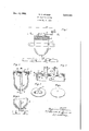
In the accompanying drawing wherein I have illustrated a practical embodiment of the principles of my invention, Fig. i is an elevation showing my invention applied to the ignition 15 system and oil pressure line of an internal combustionV engine.
Fig. 2 is a Vertical section showing the preferred form of the diaphragm chamber.
Fig. 3 is a like view of a modified form of the 20 same.
Fig. e is an enlarged broken vertical section of the diaphragm chamber and associated parts taken on a plane parallel to that of Fig. l.
Fig. 5 is a perspective showing the insulating 25 disk and the spring contact member, the disk being inverted.
Fig. 6 is a perspective of the diaphragm. Referring to the drawing, l represents pressure oil supply line of the internal combustion 30 engine in which is interposed the T-iitting 2 with its stem extending upwardly. 3 is the diaphragm cup which is mounted on the upwardly extending stem of the fitting and whose open top is exteriorly threaded. 35
The cup 3 is preferably of the construction shown in Fig. 2 and cut from a block of brass with an integral stand pipe fl extending upwardly therein to, a short distance, say about one sixteenth of an inch below the plane of the 40 top of the cup. The bore of standpipe is open through the bottom of the cup and is countersunk and threaded as at 5 adjacent to its lower end so that the cup may be mounted in a vertical position by screwing it onto the upwardly 45 extending stem of the T-tting. 3a represents a metal strap by means of which the cup may be mounted on a convenient portion of the vehicle.
However the standpipe may be a separate element, as shown in Fig. 3 wherein the bottom of 50 the cup is provided with a threaded hole 6 by means of which the cup may be screwed onto the stem of the fitting 2, and the standpipe may be a smaller tube 'l whose threaded lower end is screwed into the interi-orly threaded stem of the T-rltting. Again the tube l may be soldered in place.
However, I prefer the construction illustrated in Fig. 2 as the same is less expensive to manufacture and the elevation of the upper end of the standpipe relative to the top of the cup can not be changed as it be in connection with the structure illustrated in Fig. 3.
il represents a gasket of compressible material and of L-shaped cross sectional form which rests on the upper end of the cup 3, and s represents a diaphragm which fits down in said gasket to close the upper end ofthe cup. Said diaphragm may be formed of any suitable flexible material, such, for instance, as thin sheet brass.
It represents a stiff disk of fibre or other suitable nonccnducting material which seats down in the gasket I prefer to interpose a metal spacing ring Il between the diaphragm and disk.
I2 and i3 represent a pair of tubular terminal posts, preferably made of brass, which are rigidly xed to the nbre disk le, the base of said posts being exposed at the inner or under side of said disk.
i2 represents a spring metal contact plate of conductive material which is secured to the under or inner side of the disk Iii as by means of a rivet i5. The disk is bowed transversely as shown in Figs. 4 and 5 so that normally it is out ,of contact with the inner ends of the posts I 2 and 93 and preferably rests lightly upon the diaphragm 9.
I5 represents an annular cap provided with a depending internally threaded flange which is vscrewed on the top of the cup, and also with an "inwardly overhanging flange Il which bears on the disk Iii forcing it downwardly to hold the parts in place and to compress the gasket 8 to prevent the escape of oil from the cup past the diaphragm 9. V
I8 and le representjone-of the lead Wires of the ignition system lwhich is interrupted, the ends being connected to the posts l2 and I 3 as by screws. Y
When there is no oil pressure in the line I and the cup Si the diaphragm 9 is retracted and the spring contact plate lll is out of contact with the bases of the posts I2 and is, but when the pressure is applied to the oil the diaphragm is eX- panded upwardly, forcing the contact plate into electrical contact with the posts I2 and I3 and thus completing the conductorV I8-I9. However shouldthe pressure fall in line I and consequently in the cup 3, the `diaphragm will con- V tract, allowing the contact plate to spring away Vfrom the posts' l2 and i3, thus interrupting the conductor ISS- and thus stopping the engine. To prevent back pressure above the diaphragm I provide the disk with an air port Illa.
Thus while the oil pressure is maintained the ignition system is complete but if the oil pressure falls below the predetermined safety limit then the ignition system is automatically interrupted and the operation of the engine ceases.
Insomuch as the pressure in the oil line will be below operating pressure when the engine is not going, I provide means for temporarily connecting up the ignition system when the engine is to be started. Thus I provide a by-pass conductor 2i? the ignition system which is connected to the binding post I3, to which the conductor i9 is also connected, and said conductor 2o has inserted therein a spring-opened switch 2 l, which in the case of a motor vehicle may be .mounted on the instrument board and which thereafter maintains its operation owing to the 10 fact that sufficient oil pressure is now maintained in the line i and in the cup 3 and thus the binding posts i2 and I3 have been electrically connected by the contact plateV le, thereby completing the conductor lai-9. 15
The function of the standpipe in the cup is to maintain at all times a body of oil in the latter so that when the oil pressure fails or falls below the safety limit, the cup will not Vbe drained but will remain almost filled however with the top 20 of the oil out of contact with the diaphragm. 'Ihus when the proper pressure is reestablished the admission of a relatively small quantity of additional oil is required to extend the diaphragm and complete the ignition circuit.
This is a very important consideration, since if the cup were fully or to a material extent, drained by the failure of or fall in pressure, the cup would require refilling when the pressure is reestablished before the ignition system would be 30 l completed. ThusY the operator would be required tohold the switch 2i closed for quite: a lengthy period before the ignition system could begin normal operation.v This is particularly true in the case of the motor vehicles manu- ,35;
factured of late wherein oil lines of reduced capacity are employed.
With the standpipe extending up to within a short distance of the top of the cup, say within a sixteenth of an inch, the quantity of oil lost 40.-
by drainage from the cup when the pressure falls is relatively slight and thus this small quantity is almost instantaneously replaced when the pressure is reestablished or in other words when the engine is started with the switch 2l held 45 closed, and therefore the period within which said switch must be held closed is hardly more than a moment.
It is obvious from the foregoing that my invention is of great value. are burned out because the oil supply has been dangerously diminished or has failed or the operation of the oil pump has either ceased or been impaired. v
The operator of the motor vehicle may be un- 55 conscious of such an occurrence or he may feel that he can complete a trip before the bearings are injured. The result is burned o ut or very badly damaged bearings and engine parts.
`With the use of my invention the operation 00 of the vehicle is immediately halted when such failure occurs and the operator is compelled to have the oil supply replenished or the pump put into efficient Voperation before he can continue the normal operation ofV the vehicle. Y V55 I claim:-
l. In a self-contained safety pressure switch for use in the ignition system of an internal combustion engine which is provided with aV lubricating oil supplyV under pressure, thecombination of a vertically disposed receptacle having its upper walls cylindrical, a trap formed by Va pipe Aextending upwardly within the receptacle4 and connected at its lower end with the pressure oil supply, a disk of insulating material closing 'f5Y Frequently bearings 50 the upper end of the receptacle, a metallic diaphragm mounted within the container adjacent said disk and insulated from the container, the inner end of the pipe being closely adjacent the diaphragm, said diaphragm sealing the oil from the disk, and binding posts carried by the disk and having their bases exposed at the inner surface of the disk and said posts protruding outwardly to be connected in the ignition system, said diaphragm when expanded upwardly by normal oil pressure in the receptacle being arranged to complete the circuit between the bases of said posts but breaking the circuit when the failure of oil pressure causes the diaphragm to retract.
2. In a switch for completing the ignition circuit of an internal combustion engine which has an oil lubricating system under pressure, the combination of a sludge trap comprising an oil chamber having vertically disposed upper walls, a diaphragm closing the top of said chamber, contacts interposed in the ignition circuit and arranged to be closed by the upward expansion of said diaphragm, and means connecting said chamber with the oil lubricating system to eX- pand said diaphragm under normal oil pressure,
said means opening into said chamber at a point closely adjacent the diaphragm to prevent such a material diminution of the oil in the chamber when the oil pressure falls as would produce a material lag in the subsequent closing of the switch, and also to at all times maintain the trap substantially full of oil.
3. In a switch for completing the ignition circuit of an internal combustion engine which has an oil lubricating system under pressure, the combination with an oil chamber, a diaphragm mounted normal to the wall of said chamber and closing the same, contacts interposed in the ignition circuit and arranged to be operated by the expansion of the diaphragm, of means connecting said chamber with the oil lubricating system to expand said diaphragm under normal oil pressure, said means opening into said chamber at a point closly adjacent the diaphragm and arranged to produce an effective oil pressure chamber and a relatively deep sludge trap, the surface of the oil in the trap forming one wall of the eiective oil pressure chamber, thus providing a minimum pressure chamber.
Publications (1)
| Publication Number | Publication Date |
|---|---|
| US2024926A true US2024926A (en) | 1935-12-17 |
Family
ID=3427574
Family Applications (1)
| Application Number | Title | Priority Date | Filing Date |
|---|---|---|---|
| US2024926D Expired - Lifetime US2024926A (en) | Oil pressure switch |
Country Status (1)
| Country | Link |
|---|---|
| US (1) | US2024926A (en) |
-
0
- US US2024926D patent/US2024926A/en not_active Expired - Lifetime
Similar Documents
| Publication | Publication Date | Title |
|---|---|---|
| US3132331A (en) | Fluid level signal system | |
| US2162174A (en) | Automatic protector against over | |
| US2780692A (en) | Fluid level responsive switch | |
| US2537354A (en) | Oil pressure switch | |
| US2166498A (en) | Switching means | |
| US2466111A (en) | Pressure operated switch for hydraulic brake systems | |
| US2024926A (en) | Oil pressure switch | |
| US1951245A (en) | Pressure actuated switch | |
| US2149068A (en) | Pressure fed lubricating system | |
| US1387746A (en) | Engine-stopping device | |
| US1951882A (en) | Apparatus and method of operation of braking systems and stop lights | |
| US3499130A (en) | Safety device and method | |
| US2251648A (en) | Pressure operated electric switch | |
| US2136504A (en) | Safety device fob motors | |
| US1821853A (en) | Henby m | |
| US1975748A (en) | Ignition system for internal | |
| US2506208A (en) | Switch | |
| US1633521A (en) | Automatic switch | |
| US2465516A (en) | Float operated switch | |
| US2501660A (en) | Fluid pressure switch | |
| US1924251A (en) | Automatic drain valve | |
| US1960662A (en) | Pressure ignition switch | |
| US4135859A (en) | Pollution control device adapted for attachment to reservoir gland stuffing boxes | |
| US2191216A (en) | Circuit controller | |
| US1770264A (en) | Harvey huber eslinger |