US2024921A - Method of determining slope of subsurface rock beds - Google Patents
Method of determining slope of subsurface rock beds Download PDFInfo
- Publication number
- US2024921A US2024921A US642561A US64256132A US2024921A US 2024921 A US2024921 A US 2024921A US 642561 A US642561 A US 642561A US 64256132 A US64256132 A US 64256132A US 2024921 A US2024921 A US 2024921A
- Authority
- US
- United States
- Prior art keywords
- point
- waves
- records
- formation
- feet
- Prior art date
- Legal status (The legal status is an assumption and is not a legal conclusion. Google has not performed a legal analysis and makes no representation as to the accuracy of the status listed.)
- Expired - Lifetime
Links
- 238000000034 method Methods 0.000 title description 35
- 239000011435 rock Substances 0.000 title description 26
- 230000015572 biosynthetic process Effects 0.000 description 32
- 238000005755 formation reaction Methods 0.000 description 32
- 238000005474 detonation Methods 0.000 description 6
- 230000002596 correlated effect Effects 0.000 description 5
- 239000002360 explosive Substances 0.000 description 4
- 230000000694 effects Effects 0.000 description 3
- 239000000463 material Substances 0.000 description 3
- 230000007423 decrease Effects 0.000 description 2
- 241000581364 Clinitrachus argentatus Species 0.000 description 1
- 208000022639 SchC6pf-Schulz-Passarge syndrome Diseases 0.000 description 1
- 208000001364 Schopf-Schulz-Passarge syndrome Diseases 0.000 description 1
- 241000364021 Tulsa Species 0.000 description 1
- 238000012937 correction Methods 0.000 description 1
- 238000005553 drilling Methods 0.000 description 1
- 230000002452 interceptive effect Effects 0.000 description 1
- 150000003839 salts Chemical class 0.000 description 1
Images

Classifications
-
- G—PHYSICS
- G01—MEASURING; TESTING
- G01V—GEOPHYSICS; GRAVITATIONAL MEASUREMENTS; DETECTING MASSES OR OBJECTS; TAGS
- G01V1/00—Seismology; Seismic or acoustic prospecting or detecting
- G01V1/003—Seismic data acquisition in general, e.g. survey design
Definitions
- the velocities at which sound earths surface and reflected back by subterrawaves traverse the earth are from 10,100 to 11,- nean formations, and oscillographs for recording 000 feet per second and the slopes usually inthe amplitude of the waves.
- Fig. 2 is a diagrammatic View showing three for example, every 200 feet, in a straight line consecutive positions of a group of ve seismo- 40 from a shot point or source of sound (S. SJ. graphs for detecting sound waves originating 40
- S. SJ. graphs for detecting sound waves originating 40
- Figl 3 is a similar View showing the relative from the sound source.
- Fig. 2 wherein the full lines indicate sound waves emanating from a source of sound and reflected back by the horizon of the rock bed to the group of detectors located in a zone A at stations designated IA to 5A.
- the resulting reections detected by the ve seismographs are recorded on a single film strip in the manner indicated on the uppermost strip A of Fig. 4 of the drawings.
- the detector at station 5A is located 1,000 feet from SS, the point where the sound Wave reaching this detector strikes the rock bed is only 500 feet horizontally from SS or half Way between SS and 5A.
- the reflecting point of the wave reaching the detector at station IA is feet horizontally from SS so that the total length surveyed of the rock bed surface by the group of five detectors is only 400 feet.
- the records made at the respective stations IA2A3A4A, and 5A are correspondingly designated in Fig. 4.
- the process of obtaining records may be continued by consecutively moving the seismographs to stations ID to 5D, IE to 5E and. after it becomes impossible, because of too great an angle of incidence, to any longer obtain reflections of Waves emanating from the point SS', the source of sound is moved to the next station or SS (Fig. 1) and the group of detectors is successively placed at stations IF to 5F and so on.
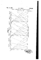
- the resulting records are finally arranged in proper correlation in much the same manner as shown in Fig. 4 and lines 6, l, 8, 9, I0, and II may be drawn across consecutive groups of records to follow a particular reflecting surface indicated by the traces. will, of course, be evident that all of the recording stations and the points of sound. source should be arranged in a straight line so that the contour of the rock bed surface is surveyed along' a correspondingly straight line.
- delta d/2 represents a delta time, or normal delta T for the level subsurface assumed.
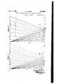
- This normal delta T increases as the surface of a rock bed declines, and increases in proportion to the inclination of the surface as illustrated in Fig. 3.
- Calculation of the slope of a subsurface bed from a record as shown in Fig. 4 is thus comparatively simple. tively loose or unconsolidated layer of weathered material extending downwardly from the surface of the earth at varying distances trans- ⁇ mits sound at a very low velocity it is necessary to first find the base of this layer', designated i5, Fig. 3, and to thereafter make the neces- .sary corrections on the records so that the final calculation will be as nearlyaccurate as possible.
- the depth of the weathered layer at each detector station may be determined by any well known method. y
- the method of profiling a subsurface formation including detonating an explosive charge at one point, recording the refiection of sound waves set up by the detonation and reflected from said formation at a series of spaced detecting' points, advancing such series of ldetecting points in definite relation to the first series of detecting points so that the rst one of the detecting points .of the second series is common to a detecting point of the first series,
- l 3 The method of profiling a subsurface forl mation including generating sound waves at a4 point above said formation, recording reception of said waves reflected from said formation at a plurality of aligned points spaced from saidgenerating point to determinefpoints of incidence ⁇ of said waves with said formation, generating similarN waves at a point spaced from said -first generating point and common to one of said points of reception, and recording reception 'of the waves reflected from saidv formation at a plurality of spaced points from the second genera'ting point, the first of 'which being wavesl reflected through the last point of incidence by a different path to provide a plurality of records whereby a continuousprofile of said formation is determined by correlation of said records.
- the method of profiling a subsurface formation including progressively vproducing at l0 spaced sources successive sets of seismic waves, ⁇ and recording reception of the sets of waves reflected from said formation at such regularly spaced distance relation to effect reception of one set of reiiected waves from one source through an incidence point on the formation common to the incidence point of a vrecorded set of re- ⁇ flected waves from an adjacent source.
- the method of profiling ya subsurface formation including producing sets of sound waves at aI common source above said formation, recording reception of the sets of waves reflected from progressively spaced incidence points on said formation and to the approach of a point producing a critical incidence angle, producing similar sets of sound waves at a point common to. one of said recording points, and recording reception of the sets of waves reflected by the formation'from said second source to establish a ⁇ series of records each having a recording common to a recording on another whereby the records are correlated to determine profile ofsaid formation. .f
- the method of profiling a subsurface formation including producing sets of sound waves at a source above said formation, recording reception of the sets of waves reflected from progressively spaced incidence points on vsaid formation and to the approach of a point producing a critical incidence angle, producing similar sets of sound Waves at a source spaced from said ⁇ first source and common to one of 'said points of reception, and recording v:recep ⁇ tion of the sets of Waves reflected by the formation from said second-source in such spaced dis-l tance relation to effect reception of one set of reflected waves from the second source through an incidence point on the formation common to an incidence point of a reflected wave recorded from the first source.
- the method of profiling a subsurface formation including detonating an explosive charge at one point, recording the reection of sound waves set up by the detonation and reected from said formation at a series of spaced detecting points, progressively advancing said series of detecting points in definite relation to the preceding series of detecting points so that one of the detecting points of a succeeding series is common to a detecting point of the preceding series, detonating an explosive charge at said first point of detonation for each series of detecting points to provide a plurality of records each having a recording common to a recording from a preceding record, and correlating said records relatively to said common recordings wherefrom a continuous prole of said formation is determined.
Landscapes
- Engineering & Computer Science (AREA)
- Remote Sensing (AREA)
- Physics & Mathematics (AREA)
- Life Sciences & Earth Sciences (AREA)
- Acoustics & Sound (AREA)
- Environmental & Geological Engineering (AREA)
- Geology (AREA)
- General Life Sciences & Earth Sciences (AREA)
- General Physics & Mathematics (AREA)
- Geophysics (AREA)
- Geophysics And Detection Of Objects (AREA)
Description
W. G. GREEN METHOD OF DETERMINING SLOPE OF SUBSURFCE ROCK BEDS` Filed NOV. 14, 1932 3 Sheets-Sheet 1 INVENTOR MNMNN mNmSQN WNNQN Wl? BY ATTORNEY Dec. 17, 1935. W Q GREEN l 024,921
METHOD OF DETERMINING SLOPE OF SUBSURFACE ROCK BEDS E Filed Nov. 14, 1952 .s sheets-sheet 2 fiy. j aw m ma ze 36 d6 .5670 55 IH 7 go Za EN lNvENToR mi/mf me ATTORN EY W. G. GREEN Dec. 17, 1935.
METHOD OF DETERMINING SLOPE OF SUBSURFACE ROCKBEDS Filed Nov. 14, 1932 s sneets-sneet' Patented Dec. 17, 1'935 A UNITED STATESv PATENT 'or-FICE METHOD F DETERMJNING SLOPE 0F SUBSURFACE ROCK BEDS vWilliam G. Green, Tulsa, Okla. V Application November 14, 1932, Serial No. 642,561
8 Claims. (Cl. 181-05) My invention relates to the art -of surveying. four detectors spaced at 200 feet intervals are subterranean areas from the surface of the used would be the difference between 100 and earth for locating formations indicating the 400 feet or 300 feet. In localities such as the presence of oil and more particularly to a meth- American Gulf Coastal area where the subsurod for determining slope of subsurface rock beds. face velocities are comparatively low or ap-4 5 In attempts to nd the approximate contours proximately 9,000 feet per second, the latter of subterranean strata and the depth at which -method is very suitable particularly in View of these formations are located, methods are comthe fact that the inclinationvof slopes around monly followed requiring the use of instruments salt domes of this area is comparatively great.
10 such as seismographs for detecting sound waves, However, in the Mid-Continent area of the 10 sent out by detonation of a shot on or near the United States the velocities at which sound earths surface and reflected back by subterrawaves traverse the earth are from 10,100 to 11,- nean formations, and oscillographs for recording 000 feet per second and the slopes usually inthe amplitude of the waves. With one excep- Cline only from 0 to 40 feet per 1,000 feet of horition all of the methods practiced in the above zontal length of a subsurface stratum, It will 15 manner, of which I am aware, depend on the thus be evident that the latter method is un# correlation of records obtained from several difreliable for use in high velocity material since ferent points, the correlated records indicating v the dierence in time noted between the lirst the dierence in slope of a bed lat different and last-instruments would be so small as to points. If the records are correctly correlated make an accurate selection and reading ofthe 50 the computation of slope therefrom is a relativerecords extremely diicult and Often impossible.
ly simple matter. However, it is often extremely It is the principal object of my invention dicult because of interfering waves and lack therefore, t0 eliminate the. COIlfllSiOi incident t0 of clarity of the records for various reasons to practicing the foregoing methods and t0 PIO- accurately and positively correlate the reiiection vide a method whereby slope of subsurface rocks impulses and the drilling of numerous wells at beds can be mOI'B Positively and allaiely degreat expense has proved that the conclusions termined. v
arrived at by the above method are frequently This object I accomplish primarily by surveyunreliable. ing as great a continuous length of the reect- 3@ The single exception referredto above is a ing horizon as required for definitely indicating method used in low velocity material where a, the contour prole oi'` the rock bed and have difference in time between the first and last re-v illustrated SSPS and XeSlllS 0f this' mefJhOd in cording instruments on one set-up of instruthe accompanying drawings, wherein: ments is used to determine the slope of the sub- Fig. 1 iS a da'ammeti View illlllrating the surface bed between two depth points corresuccessive positioning oi detectors and sound spending to these instruments. In following Sources for surveying an extended area of a rock this method, the usual practice is to space four bed. seismograph detectors at regular intervals, as Fig. 2 is a diagrammatic View showing three for example, every 200 feet, in a straight line consecutive positions of a group of ve seismo- 40 from a shot point or source of sound (S. SJ. graphs for detecting sound waves originating 40 Thus, the four consecutive instruments would from a single shot point. be respectively spaced 200, 400, 600 and 800 feet Figl 3 is a similar View showing the relative from the sound source. From well known laws decrease and increase in distances travelled by the depth determined by the record obtained sound waves reflected respectively from inclined 4@ from the rst instrument (200 feet from S. S.) and declined reflecting horizons. 45 would be that of a vertical line extending e is a copy of a set of correlated records downwardly from a point half way between the obtained by Iollowingrny improved method.
S. S. and first instrument to the reflecting hori- Referring more in detail to the drawings: zon or rock bed. The depth point determined The lines l and 2 respectively designate the 5U' by a record from the last instrument (800 feet earths surface and the surface of a subterranean v0 from S. S.) would accordingly be 400 feet h cuin rock bed. A sound source or shot point, usually zcntaliy from the source oi sound, considering comprising a charge of dynamite, is designated the subsurface to be level. Consequently, the by SS and seismograph detectors are indicated actual horizontal length of subsurface area surby the numeral 3. The arrangement and equal yeyed by this method when a single Si. S. and spacing of the detectors in a line with the SS 5a is particularly illustrated in Fig. 2 wherein the full lines indicate sound waves emanating from a source of sound and reflected back by the horizon of the rock bed to the group of detectors located in a zone A at stations designated IA to 5A.
The resulting reections detected by the ve seismographs are recorded on a single film strip in the manner indicated on the uppermost strip A of Fig. 4 of the drawings. As above referred to, it will be noted, however, that if the detector at station 5A is located 1,000 feet from SS, the point where the sound Wave reaching this detector strikes the rock bed is only 500 feet horizontally from SS or half Way between SS and 5A. Similarly, the reflecting point of the wave reaching the detector at station IA is feet horizontally from SS so that the total length surveyed of the rock bed surface by the group of five detectors is only 400 feet. The records made at the respective stations IA2A3A4A, and 5A are correspondingly designated in Fig. 4.
Assuming that the surface of the bed inclined 10 feet to every 1,000 feet of horizontal length it will be readily evident that the 4 foot rise in the length surveyed would result in such a small difference in the time of arrival of the waves at the rst and last detectors from the normal time of arrival if the surface were level that the records would be of little or no value since it would be impossible to make accurate computations therefrom.
Upon obtaining the first record I, therefore, move the five detectors respectively to a zone B including the live stations indicated at IB to 5B, the station IB being identical with the station 5A so that the last record on one lm Will be as nearly like the first record of the next lm as is possible.
Another shot is then detonated at SS and the resulting Waves, indicated by the dot and dash lines in Fig. 2 are recorded by the group of five detectors at their stations in zone B. The lin B thus obtained is correlated with and mounted' adjacent 4the first lm A as in Fig. 4. 'I'his is readily accomplished by comparing the trace 5A on lm A with the trace IB on film B. Since they were made at the saine station and from the same shot point SS they would be' substantially alike although they may vary slightly in intensity due to the fact that the detector Was previously moved from IA to IB so that differences in ground contact or possibly differences in depth of the holes in which the detector was planted may have affected the character of the traces. However the counted vibrations are the same. 'I'he actual distance surveyed on the rock bed surface has now been increased to 800 feet and by repeating the foregoing steps and moving the detectors to stations IC to 5C in zone C so that the sound waves indicated by dotted lines (Fig. 2) are recorded at this location, the surveyed distance is further increased to 1,200 feet.
Considering the inclination of the slope to have continued at the rate of 10 feet per 1,000 feet the last depth point recorded would be only 12 feet nearer the earths surface than the rst recorded depth point, an elevational difference so small that accurate computations from the records thus far obtained Would probably be impossible. The groups of detectors are, therefore, successively moved to stations ID to 5D in zone D and IE to 5E in zone E (Fig. 1) -and the previously described steps repeated for obtaining record lms D" and E. This process may be continued indefinitely or until the angle of incidence to the subsurface rock bed increases to the critical angle of refraction. It is, therefore, possible to survey from one shot point a distance on the rock bed approximately equal to the depth of the bed below the surface of the earth.
In order to carry the steps of surveying still further it now becomes necessary to move the SS to the point SS (Fig. 1) and it should be noted that this point is so arranged in a straight line with the previous detector stations that the Waves from the rst detonated shot at the new sound source and picked up by the iirst detector or 3C adjacent this source strikes the rock bed at the identical point where the last recorded Wave from SS struck the bed thereby producing a record as nearly as possible like the last record theretofore obtained.
Thereupon the process of obtaining records may be continued by consecutively moving the seismographs to stations ID to 5D, IE to 5E and. after it becomes impossible, because of too great an angle of incidence, to any longer obtain reflections of Waves emanating from the point SS', the source of sound is moved to the next station or SS (Fig. 1) and the group of detectors is successively placed at stations IF to 5F and so on. The resulting records are finally arranged in proper correlation in much the same manner as shown in Fig. 4 and lines 6, l, 8, 9, I0, and II may be drawn across consecutive groups of records to follow a particular reflecting surface indicated by the traces. will, of course, be evident that all of the recording stations and the points of sound. source should be arranged in a straight line so that the contour of the rock bed surface is surveyed along' a correspondingly straight line.
As will be notedI from the copy of a'n actual record (Fig. 4) the first portions of the traces are frequently indefinite due to the excessive initial amplitude of the waves but the latter portions are clear and by having a number of records showing the results of surveying an extensive area it is possible to determine With accuracy the general slope of a subsurface rock bed.
The procedure of calculating the depths of a bed from records divided by transverse lines I3 into equal time intervals is well known to those skilled in-the art. For computation purposes it is desirable to assume the rock bed to be level as shown in Fig. 2, and it will be clear from this figure that the depth obtained from the rst instrument reflection at Station IA is approximately one-half the distance from SS to the rock bed and back to the deector at this station or d/2. Since the record of the reflecting Wave takes nothing into account except the time consumed in traversing the path from SS to the rock bed and back to station IA, d is recorded as a function of the time T of the reflection.
By taking the station ASS as a center and swinging an arc I4 from the rock bed it is found that the length of path traversed by the waves increases in proportionto the spacing of the detectors from the sound source. Thusl the increase in the path d/2 as the distance of the detector from SS increases is designated delta d/2 which represents a delta time, or normal delta T for the level subsurface assumed. This normal delta T increases as the surface of a rock bed declines, and increases in proportion to the inclination of the surface as illustrated in Fig. 3.
If, on computing the recorded reflections of an instrument set-up a delta time is observed which differs from the expected delta T, this difference, after correcting for elevations, weathering, etc., would be due-to the difference in time required for the waves to travel their paths and would designate the slope of the bed. Therefore, the difference between the normal expected delta T and the observed delta T for any particular distance from the S. S. will be the result of a slope in the surveyed portion of the surface of the rock bed.
For the purposes of simplifying and expediting the computation of records obtained by the method above described a graphical solution has been worked out whereby the amount and direction of a slope may be accurately ascertained. Formulas showing the relation of the various quantities may also be derived to simplify the process of calculating the amount of slope.
Calculation of the slope of a subsurface bed from a record as shown in Fig. 4 is thus comparatively simple. tively loose or unconsolidated layer of weathered material extending downwardly from the surface of the earth at varying distances trans-` mits sound at a very low velocity it is necessary to first find the base of this layer', designated i5, Fig. 3, and to thereafter make the neces- .sary corrections on the records so that the final calculation will be as nearlyaccurate as possible. The depth of the weathered layer at each detector station may be determined by any well known method. y
In practice I compute this depth by the refraction method from the first arrival time of the records, this time being indicated by a sudden break in a trace near its beginning as shown at I5 on the fourth record strip of Fig. 4. The indication, in the trace, of the exact instant at which the shot was detonated would be to the left of the break I5 and is not shown in this figure. j
From the foregoing it will be apparent` that in practicing thepresent invention, a positive correlation of various records and an accurate and reliable calculation of depths is made possible. Since the difference in depth from one point to another can be accurately determined and this process continued indefinitely it is possible with my method to obtain a complete profile of the surveyed slope of a subsurface -rock bed. In order to check the computations made on the records obtained by the process above de.
scribed the same procedure may be followed but in the reverse direction, thus producing an effect opposite Yto the former, i. e., an incline indicated by the latter should correspond to a decline disclosed by the former procedure and vice versa.
What I claim and desire to secure by Letters Patent is:
i. The method of profiling a subsurface formation including detonating an explosive charge at one point, recording the refiection of sound waves set up by the detonation and reflected from said formation at a series of spaced detecting' points, advancing such series of ldetecting points in definite relation to the first series of detecting points so that the rst one of the detecting points .of the second series is common to a detecting point of the first series,
detonating a second explosive charge at said However, because the relarst point of detonation, recording the sound waves set up by the second detonation and reflected from said formation to said second series of detecting points, and correlatingsaid records relatively to recordings from said common detect- 5 ing points wherefrom a continuous prole of said f formation is determined.
dence by a different path to provide a plurality of records whereby profile of said `formation is 20 determined by correlation of said records. l 3. The method of profiling a subsurface forl mation including generating sound waves at a4 point above said formation, recording reception of said waves reflected from said formation at a plurality of aligned points spaced from saidgenerating point to determinefpoints of incidence `of said waves with said formation, generating similarN waves at a point spaced from said -first generating point and common to one of said points of reception, and recording reception 'of the waves reflected from saidv formation at a plurality of spaced points from the second genera'ting point, the first of 'which being wavesl reflected through the last point of incidence by a different path to provide a plurality of records whereby a continuousprofile of said formation is determined by correlation of said records.
4. The method of profiling a subsurface formation including progressively vproducing at l0 spaced sources successive sets of seismic waves,` and recording reception of the sets of waves reflected from said formation at such regularly spaced distance relation to effect reception of one set of reiiected waves from one source through an incidence point on the formation common to the incidence point of a vrecorded set of re-` flected waves from an adjacent source.
5. The method of profiling ya subsurface formation including producing sets of sound waves at aI common source above said formation, recording reception of the sets of waves reflected from progressively spaced incidence points on said formation and to the approach of a point producing a critical incidence angle, producing similar sets of sound waves at a point common to. one of said recording points, and recording reception of the sets of waves reflected by the formation'from said second source to establish a` series of records each having a recording common to a recording on another whereby the records are correlated to determine profile ofsaid formation. .f
6. The method of profiling a subsurface formation including producing sets of sound waves at a source above said formation, recording reception of the sets of waves reflected from progressively spaced incidence points on vsaid formation and to the approach of a point producing a critical incidence angle, producing similar sets of sound Waves at a source spaced from said`first source and common to one of 'said points of reception, and recording v:recep\ tion of the sets of Waves reflected by the formation from said second-source in such spaced dis-l tance relation to effect reception of one set of reflected waves from the second source through an incidence point on the formation common to an incidence point of a reflected wave recorded from the first source.
7. The method of profiling a subsurface formation including detonating an explosive charge at one point, recording the reection of sound waves set up by the detonation and reected from said formation at a series of spaced detecting points, progressively advancing said series of detecting points in definite relation to the preceding series of detecting points so that one of the detecting points of a succeeding series is common to a detecting point of the preceding series, detonating an explosive charge at said first point of detonation for each series of detecting points to provide a plurality of records each having a recording common to a recording from a preceding record, and correlating said records relatively to said common recordings wherefrom a continuous prole of said formation is determined.
8. The method of proling a subsurface formation including generating sound waves at a point above said formation', recording reception of said sound waves r'eected from said formation at a plurality of spaced points, generating a similar set of waves at the point of reception of one of said reflected waves from the rst generating point, and recording reception of the waves reilected by( the formation from said second generating point at a plurality of spaced points including one of the rst points of reception to provide a plurality of records each 15 WILLIAM G. GREEN. 20
Priority Applications (1)
| Application Number | Priority Date | Filing Date | Title |
|---|---|---|---|
| US642561A US2024921A (en) | 1932-11-14 | 1932-11-14 | Method of determining slope of subsurface rock beds |
Applications Claiming Priority (1)
| Application Number | Priority Date | Filing Date | Title |
|---|---|---|---|
| US642561A US2024921A (en) | 1932-11-14 | 1932-11-14 | Method of determining slope of subsurface rock beds |
Publications (1)
| Publication Number | Publication Date |
|---|---|
| US2024921A true US2024921A (en) | 1935-12-17 |
Family
ID=24577106
Family Applications (1)
| Application Number | Title | Priority Date | Filing Date |
|---|---|---|---|
| US642561A Expired - Lifetime US2024921A (en) | 1932-11-14 | 1932-11-14 | Method of determining slope of subsurface rock beds |
Country Status (1)
| Country | Link |
|---|---|
| US (1) | US2024921A (en) |
Cited By (5)
| Publication number | Priority date | Publication date | Assignee | Title |
|---|---|---|---|---|
| US2499605A (en) * | 1943-02-25 | 1950-03-07 | Nicolson Alexander Mclean | Method and apparatus for detecting waves |
| US2539220A (en) * | 1944-06-22 | 1951-01-23 | Continental Oil Co | Seismographic record correlation system |
| US2732906A (en) * | 1950-07-07 | 1956-01-31 | William Harry Mayne | Seismic surveying |
| US3212600A (en) * | 1961-12-28 | 1965-10-19 | Phillips Petroleum Co | Seismic exploration of water covered areas |
| US20210333424A1 (en) * | 2020-04-23 | 2021-10-28 | Saudi Arabian Oil Company | Methods and Systems for Gridding of Salt Structures |
-
1932
- 1932-11-14 US US642561A patent/US2024921A/en not_active Expired - Lifetime
Cited By (6)
| Publication number | Priority date | Publication date | Assignee | Title |
|---|---|---|---|---|
| US2499605A (en) * | 1943-02-25 | 1950-03-07 | Nicolson Alexander Mclean | Method and apparatus for detecting waves |
| US2539220A (en) * | 1944-06-22 | 1951-01-23 | Continental Oil Co | Seismographic record correlation system |
| US2732906A (en) * | 1950-07-07 | 1956-01-31 | William Harry Mayne | Seismic surveying |
| US3212600A (en) * | 1961-12-28 | 1965-10-19 | Phillips Petroleum Co | Seismic exploration of water covered areas |
| US20210333424A1 (en) * | 2020-04-23 | 2021-10-28 | Saudi Arabian Oil Company | Methods and Systems for Gridding of Salt Structures |
| US11714208B2 (en) * | 2020-04-23 | 2023-08-01 | Saudi Arabian Oil Company | Methods and systems for gridding of salt structures |
Similar Documents
| Publication | Publication Date | Title |
|---|---|---|
| Hagedoorn | The plus‐minus method of interpreting seismic refraction sections | |
| US2732906A (en) | Seismic surveying | |
| Rockwell | A general wavefront method | |
| US2321450A (en) | Seismic surveying | |
| US1899970A (en) | Seismic exploration of geologic formations | |
| US2555806A (en) | Seismic prospecting method, including generation of a cylindrical wave front | |
| US2024921A (en) | Method of determining slope of subsurface rock beds | |
| US2329721A (en) | Geophysical exploration system | |
| US3417370A (en) | Seismic velocity correlation | |
| GB2066467A (en) | Process and an apparatus for seismic geophysics with processing by focuses | |
| Weatherby | The history and development of seismic prospecting | |
| US2596463A (en) | Method for determining subsurface geological structure by seismic surveying employing refraction shooting | |
| US2156624A (en) | Subsurface seismic surveying | |
| Van Melle et al. | Ghost reflections caused by energy initially reflected above the level of the shot | |
| US2331080A (en) | Method of seismic reflection surveying | |
| US2503904A (en) | Seismic prospecting method | |
| US1799398A (en) | Method of recording seismic waves | |
| US2154548A (en) | Seismic surveying | |
| US2148422A (en) | Method of determining the dips of geological strata with substantially vertical reflections | |
| US3354985A (en) | Seismic prospecting method of locating a suspected fault | |
| US2449921A (en) | Seismic method of locating faults | |
| US2117365A (en) | Seismic surveying | |
| US3018838A (en) | Method of seismic prospecting | |
| US2153920A (en) | Seismograph prospecting | |
| RU2445651C2 (en) | Method to build seismic depth and/or time section "kong-macro" (versions) |