US2024913A - Detachable pouring spout - Google Patents
Detachable pouring spout Download PDFInfo
- Publication number
- US2024913A US2024913A US31906A US3190635A US2024913A US 2024913 A US2024913 A US 2024913A US 31906 A US31906 A US 31906A US 3190635 A US3190635 A US 3190635A US 2024913 A US2024913 A US 2024913A
- Authority
- US
- United States
- Prior art keywords
- container
- stem
- pouring spout
- cutter
- detachable
- Prior art date
- Legal status (The legal status is an assumption and is not a legal conclusion. Google has not performed a legal analysis and makes no representation as to the accuracy of the status listed.)
- Expired - Lifetime
Links
- 239000007788 liquid Substances 0.000 description 12
- 230000008020 evaporation Effects 0.000 description 4
- 238000001704 evaporation Methods 0.000 description 4
- 230000000149 penetrating effect Effects 0.000 description 4
- 238000004873 anchoring Methods 0.000 description 2
- 238000011109 contamination Methods 0.000 description 2
- 235000013290 Sagittaria latifolia Nutrition 0.000 description 1
- 230000015572 biosynthetic process Effects 0.000 description 1
- 235000015246 common arrowhead Nutrition 0.000 description 1
- 238000010276 construction Methods 0.000 description 1
- 238000012856 packing Methods 0.000 description 1
- 230000035515 penetration Effects 0.000 description 1
- 238000007789 sealing Methods 0.000 description 1
Images
Classifications
-
- B—PERFORMING OPERATIONS; TRANSPORTING
- B67—OPENING, CLOSING OR CLEANING BOTTLES, JARS OR SIMILAR CONTAINERS; LIQUID HANDLING
- B67B—APPLYING CLOSURE MEMBERS TO BOTTLES JARS, OR SIMILAR CONTAINERS; OPENING CLOSED CONTAINERS
- B67B7/00—Hand- or power-operated devices for opening closed containers
- B67B7/24—Hole-piercing devices
- B67B7/26—Hole-piercing devices combined with spouts
Definitions
- This invention relates to detachable pouring spouts for sealed containers, and has for the primary object the provision of a device of this character which is easy to apply and at the same time forms in the container a port so that the liquid content thereof may enter the device when the container is tilted for passage through said device in a controlled or restricted flow to permit dispensing of the liquid content without danger of spilling.l
- Another object of this invention is the provision of means. whereby the device may be secured to the container with a liquid seal to prevent evaporation of the liquid content of the container when the latter has been once opened and not emptied.
- this invention consists in certain novel features of construction, combination and arrangement of parts to be hereinafter more fully described and claimed.
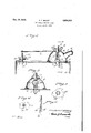
- Figure 1 is a fragmentary vertical sectional viewshowing a detachable pouring spout adapted to a container and constructed in accordance with my invention.
- Figure 2 is a sectional view taken on the line 2-2 of Figure l.
- Figure 3 is a sectional view taken on the line 3 3 of Figure 1.
- Figure 4 is a. sectionalvview taken on the line 4-4 of Figure 1.
- Figure 5 is a detail sectional view showing a modified form of my invention.
- the numeral I indicates a conventional type of sealed container employed for sealing liquids to prevent inferior liquids from being sold in lieu of a requested brand and quality of liquid.
- a container of this kind is minus any means of pouring or dispensing its contents and if opened in the ordinary manner it is difcult to dispense the liquid without danger of spilling or Wasting.
- To equip a container of this kind with a. pennanent dispensing medium would, besides materially increasing its cost, render handling of the container and thel packing of the container with others difficult.
- a container of the character described can be readily opened and the content poured therefrom without danger of spilling and which will also act as an effective seal or closure for vthe container when once opened whereby any liquid left in the container will be protected against evaporation or contamination by foreign matter.
- My invention is hereinafter described in detail and consists of an inverted substantially dome- 5 shaped member 2 forming a receptacle to receive the content of the container when the latter has been opened by my invention and tilted and has formed integrally with one side thereof a pouring spout 3 closed by a removable 10 cap 4.
- the edges of the member 2 are equipped with a gasket 5 to contact the top or a wall of the container I, as shown in Figure 1.
- the member 2 has an opening 6 through which extends .a stem 1, a portion of ⁇ which is screw 16 threaded, as. shown at 8, and projects outwardly of the member 2 and has threaded thereon a.
- wing nut 9 A slot I0 is formed in the stem through which a guide pin II extends.
- the pin II is suitably secured to opposite walls of the 20 member 2.
- a cutter I2 Secured to the inner end of the 'stem 1 is a cutter I2 which is of hollow formation and of elliptical shape in cross section and has its free end cut on an angle and sharpened so that when brought in contact with the con- I tainer with force it will readily penetrate the container.
- Notches I3 are provided in opposite sides of the cutter I2 between its cutting end and the attached end for the purpose of receiving opposite walls of the opening formed in the container by turning the ⁇ cutter through rotation of the stem 1 after the penetration of the container by the cutter.
- the shoulders I4 of the cutter defined by the notches I3 underlie the inner face of the punctured wall of the container preventing Withdrawal of the cutter from the container.
- the wing nut By turning the wing nut tightly down against the member 2, the latter or gasket 5 thereof is forced tightly against the wall of the container about the punctured opening in the container and with the pouring spout 3 closed by the cap 4 the container is sealed to prevent evaporation of the content.
- the content can be readily dispensed by tilting the container with the cap 4 removed from the spout 3 45 in a controlled fiow.
- a vent opening forming device I5 consisting of a screw threaded stem I6, in this instance connected to the stem 1 50 by a strip I1.
- some other means may be provided for the connection between the stem I5 and the stem 1.4 'Ihe stem I6 terminates at one end in an arrow head shape to form a penetrating portion I8.
- a wing nut I9 is threaded 55 the application of the pouring device tothe container, the end I8 of the stem I6 is forced through the container and the wing nut turned to bring the gasket tightly against the wall of the container to close the opening formed by the penetrating end I8 of the stem.
- a device which is compact, simple, and easily applied to a container for the purpose of forming therein openings, one of which to admit the liquid content of the container to and through the pouring spout of the device during tilting of the container and the other to admit atmospheric pressure to the interior of the container during the dispensing of its content. Further, it will be noted that the device will effectively close the container when once opened to prevent evaporation and contamination of the content.
- the stem 'I may have one end shaped to form a cutter 2l in lieu of employing a separable cutter I2.
- the stem 1 in this instance is equipped with the notches Ill and the slot I Il thereof extends through the end ofthe stem having the cutter 2I so that the liquid content of the container may pass through the slot Il! into the member 2 during the tilting of the container instead of through the notches I3 of the cutter I2.
- a detachable pouring spout and closure for sealed containers comprising a closure member to engage a container, a pouring spout for said on ⁇ the stem I6 and carries a gasket 20.
- a removable cap for said pouring spout After member, a removable cap for said pouring spout, a s tem slidably connected to said closure member and extending exteriorly thereof and screw threaded, a combined cutting and anchoring medium carried by said stem to form an opening in the container and to secure said stem to the container in a given position, a gasket carried by said closure member to contact the container, an attaching medium connected to the stem, a second stem connected 10 to the attaching medium and having one end shaped to form a penetrating point to pass through the container to form a vent opening, and means movably mounted on the second stem for closing the vent opening.
- a detachable pouring spout and closure for sealed containers comprising a closure member to engage a container, a pouring spout for said member, a removable cap for said pouring spout,
- a stem slidably connected to said closure mem- 2Q ber and extending exteriorly thereof and screw threaded, a combined cutting and anchoring me-l dium can'ied by said stem to form an opening in 'the container and t'o secure said stem to the container when in a given position, a gasket carried by said closure member to contact the container, an attaching' medium connectedr to the stem, a second stem connected to the attaching medium and having one end shaped to form a penetrating point to pass through the container to form a vent opening, a nutthreaded to the second stem, a gasket carried by the secondnamed nut to contact the container about the vent opening for closing the latter.
- a detachable pouring spout and clure for sealed containers comprising a closure member, a stem adjustabiy secured to the closure member, means for adjusting said stem, a cutter carried by said stem and including a holiJw portion opening outwardly through one end thereof and having said end cut away to provide a cutting portion, said hollow portion between the stem and the cutting portion being notched to provide ports and shoulders.
Landscapes
- Engineering & Computer Science (AREA)
- Mechanical Engineering (AREA)
- Closures For Containers (AREA)
Description
. 17, 1935. E. F. DILLEY DETACHABL POURING SPOUT.
Filed Ju1`y 17, 1935 ATTORNEY Patented Dec. 17, 1935 UNITED STATE-syrefrein" Nori-fici:
DETACHABLE POURING sPoU'r Edward F. Dilley, Williamsport, Ind.
Application July 17, 1935, Serial No. 31,906
a claims. (c1. azi-'23) This invention relates to detachable pouring spouts for sealed containers, and has for the primary object the provision of a device of this character which is easy to apply and at the same time forms in the container a port so that the liquid content thereof may enter the device when the container is tilted for passage through said device in a controlled or restricted flow to permit dispensing of the liquid content without danger of spilling.l
Another object of this invention is the provision of means. whereby the device may be secured to the container with a liquid seal to prevent evaporation of the liquid content of the container when the latter has been once opened and not emptied.
With these and other objects in view, this invention consists in certain novel features of construction, combination and arrangement of parts to be hereinafter more fully described and claimed.
For a complete understanding of my invention, reference is to be had to the following description and accompanying drawing, in which Figure 1 'is a fragmentary vertical sectional viewshowing a detachable pouring spout adapted to a container and constructed in accordance with my invention.
Figure 2 is a sectional view taken on the line 2-2 of Figure l.
Figure 3 is a sectional view taken on the line 3 3 of Figure 1.
Figure 4 is a. sectionalvview taken on the line 4-4 of Figure 1.
Figure 5 is a detail sectional view showing a modified form of my invention.
Referring in detail to the drawing, the numeral I indicates a conventional type of sealed container employed for sealing liquids to prevent inferior liquids from being sold in lieu of a requested brand and quality of liquid. A container of this kind is minus any means of pouring or dispensing its contents and if opened in the ordinary manner it is difcult to dispense the liquid without danger of spilling or Wasting. To equip a container of this kind with a. pennanent dispensing medium would, besides materially increasing its cost, render handling of the container and thel packing of the container with others difficult. Therefore, with the use of my invention a container of the character described can be readily opened and the content poured therefrom without danger of spilling and which will also act as an effective seal or closure for vthe container when once opened whereby any liquid left in the container will be protected against evaporation or contamination by foreign matter.
My invention is hereinafter described in detail and consists of an inverted substantially dome- 5 shaped member 2 forming a receptacle to receive the content of the container when the latter has been opened by my invention and tilted and has formed integrally with one side thereof a pouring spout 3 closed by a removable 10 cap 4. The edges of the member 2 are equipped with a gasket 5 to contact the top or a wall of the container I, as shown in Figure 1. The member 2 has an opening 6 through which extends .a stem 1, a portion of `which is screw 16 threaded, as. shown at 8, and projects outwardly of the member 2 and has threaded thereon a. wing nut 9. A slot I0 is formed in the stem through which a guide pin II extends. The pin II is suitably secured to opposite walls of the 20 member 2. Secured to the inner end of the 'stem 1 is a cutter I2 which is of hollow formation and of elliptical shape in cross section and has its free end cut on an angle and sharpened so that when brought in contact with the con- I tainer with force it will readily penetrate the container.I Notches I3 are provided in opposite sides of the cutter I2 between its cutting end and the attached end for the purpose of receiving opposite walls of the opening formed in the container by turning the `cutter through rotation of the stem 1 after the penetration of the container by the cutter. The shoulders I4 of the cutter defined by the notches I3 underlie the inner face of the punctured wall of the container preventing Withdrawal of the cutter from the container. By turning the wing nut tightly down against the member 2, the latter or gasket 5 thereof is forced tightly against the wall of the container about the punctured opening in the container and with the pouring spout 3 closed by the cap 4 the container is sealed to prevent evaporation of the content. The content can be readily dispensed by tilting the container with the cap 4 removed from the spout 3 45 in a controlled fiow.
Suitably'secured to the stem 1 or to some other part of the device described is a vent opening forming device I5 consisting of a screw threaded stem I6, in this instance connected to the stem 1 50 by a strip I1. However, some other means may be provided for the connection between the stem I5 and the stem 1.4 'Ihe stem I6 terminates at one end in an arrow head shape to form a penetrating portion I8. A wing nut I9 is threaded 55 the application of the pouring device tothe container, the end I8 of the stem I6 is forced through the container and the wing nut turned to bring the gasket tightly against the wall of the container to close the opening formed by the penetrating end I8 of the stem. When dispensing liquid from the container the wing nut shown in Figure 1, to prevent accidental withdrawal of the stem IIi from the container.
From the foregoing description taken in connection with the accompanying drawing, it will be seen that a device has been provided which is compact, simple, and easily applied to a container for the purpose of forming therein openings, one of which to admit the liquid content of the container to and through the pouring spout of the device during tilting of the container and the other to admit atmospheric pressure to the interior of the container during the dispensing of its content. Further, it will be noted that the device will effectively close the container when once opened to prevent evaporation and contamination of the content.
Referring to my modified form of invention,
as shown in Figure 5, the stem 'I may have one end shaped to form a cutter 2l in lieu of employing a separable cutter I2. The stem 1 in this instance is equipped with the notches Ill and the slot I Il thereof extends through the end ofthe stem having the cutter 2I so that the liquid content of the container may pass through the slot Il! into the member 2 during the tilting of the container instead of through the notches I3 of the cutter I2.
Having described the invention, I claim:
1. A detachable pouring spout and closure for sealed containers comprising a closure member to engage a container, a pouring spout for said on `the stem I6 and carries a gasket 20. After member, a removable cap for said pouring spout, a s tem slidably connected to said closure member and extending exteriorly thereof and screw threaded, a combined cutting and anchoring medium carried by said stem to form an opening in the container and to secure said stem to the container in a given position, a gasket carried by said closure member to contact the container, an attaching medium connected to the stem, a second stem connected 10 to the attaching medium and having one end shaped to form a penetrating point to pass through the container to form a vent opening, and means movably mounted on the second stem for closing the vent opening. L
2. A detachable pouring spout and closure for sealed containers comprising a closure member to engage a container, a pouring spout for said member, a removable cap for said pouring spout,
a stem slidably connected to said closure mem- 2Q ber and extending exteriorly thereof and screw threaded, a combined cutting and anchoring me-l dium can'ied by said stem to form an opening in 'the container and t'o secure said stem to the container when in a given position, a gasket carried by said closure member to contact the container, an attaching' medium connectedr to the stem, a second stem connected to the attaching medium and having one end shaped to form a penetrating point to pass through the container to form a vent opening, a nutthreaded to the second stem, a gasket carried by the secondnamed nut to contact the container about the vent opening for closing the latter.
3. A detachable pouring spout and clure for sealed containers comprising a closure member, a stem adjustabiy secured to the closure member, means for adjusting said stem, a cutter carried by said stem and including a holiJw portion opening outwardly through one end thereof and having said end cut away to provide a cutting portion, said hollow portion between the stem and the cutting portion being notched to provide ports and shoulders.
EDWARD F. DILLEY.
Priority Applications (1)
| Application Number | Priority Date | Filing Date | Title |
|---|---|---|---|
| US31906A US2024913A (en) | 1935-07-17 | 1935-07-17 | Detachable pouring spout |
Applications Claiming Priority (1)
| Application Number | Priority Date | Filing Date | Title |
|---|---|---|---|
| US31906A US2024913A (en) | 1935-07-17 | 1935-07-17 | Detachable pouring spout |
Publications (1)
| Publication Number | Publication Date |
|---|---|
| US2024913A true US2024913A (en) | 1935-12-17 |
Family
ID=21862048
Family Applications (1)
| Application Number | Title | Priority Date | Filing Date |
|---|---|---|---|
| US31906A Expired - Lifetime US2024913A (en) | 1935-07-17 | 1935-07-17 | Detachable pouring spout |
Country Status (1)
| Country | Link |
|---|---|
| US (1) | US2024913A (en) |
Cited By (4)
| Publication number | Priority date | Publication date | Assignee | Title |
|---|---|---|---|---|
| US2671576A (en) * | 1952-11-26 | 1954-03-09 | Harry E Kuehn | Can opening and contents dispensing device |
| US2975938A (en) * | 1958-12-31 | 1961-03-21 | William J Ruano | Can spout |
| US2999612A (en) * | 1958-10-20 | 1961-09-12 | Ralph A Valvano | Can opener and sealer |
| US3071286A (en) * | 1960-07-13 | 1963-01-01 | Ralph A Valvano | Can opener and sealer |
-
1935
- 1935-07-17 US US31906A patent/US2024913A/en not_active Expired - Lifetime
Cited By (4)
| Publication number | Priority date | Publication date | Assignee | Title |
|---|---|---|---|---|
| US2671576A (en) * | 1952-11-26 | 1954-03-09 | Harry E Kuehn | Can opening and contents dispensing device |
| US2999612A (en) * | 1958-10-20 | 1961-09-12 | Ralph A Valvano | Can opener and sealer |
| US2975938A (en) * | 1958-12-31 | 1961-03-21 | William J Ruano | Can spout |
| US3071286A (en) * | 1960-07-13 | 1963-01-01 | Ralph A Valvano | Can opener and sealer |
Similar Documents
| Publication | Publication Date | Title |
|---|---|---|
| US3262612A (en) | Receptacle closures | |
| US3750915A (en) | Wine pourer and resealer | |
| US5497909A (en) | Reuseable pouch fitment | |
| US3333740A (en) | Screw actuated dispenser | |
| US2073292A (en) | Dispensing closure | |
| AU2016417798A1 (en) | Plastic cover for cans with opener for opening and re-closure | |
| US2324338A (en) | Pouring can | |
| US2024913A (en) | Detachable pouring spout | |
| US2919057A (en) | Container closure and pouring spout | |
| US1726642A (en) | Tube container and closure therefor | |
| US1963050A (en) | Bottle cap | |
| US1556206A (en) | Detachable can spout and opener | |
| US2061462A (en) | Handy top for containers | |
| US20130068799A1 (en) | Retractable spout assemblies for containers, and containers having such assemblies mounted therein | |
| US3406879A (en) | Reclosable dispensing cap | |
| US2142644A (en) | Valve controlled bottle closure | |
| US1943314A (en) | Captive screw cap for cans | |
| US2119502A (en) | Metallic receptacle | |
| US2042772A (en) | Honey gate | |
| US2780396A (en) | Liquid dispensing device | |
| US2110697A (en) | Serving device for cans | |
| US1615127A (en) | Collapsible tube | |
| US2006963A (en) | Container | |
| JPS6435828U (en) | ||
| US2234168A (en) | Nozzle and closure therefor |