US20240417841A1 - Coating for hydraulic rods and other sliding components and method of producing the same - Google Patents
Coating for hydraulic rods and other sliding components and method of producing the same Download PDFInfo
- Publication number
- US20240417841A1 US20240417841A1 US18/334,782 US202318334782A US2024417841A1 US 20240417841 A1 US20240417841 A1 US 20240417841A1 US 202318334782 A US202318334782 A US 202318334782A US 2024417841 A1 US2024417841 A1 US 2024417841A1
- Authority
- US
- United States
- Prior art keywords
- coating
- thermal spray
- size distribution
- particle size
- gas
- Prior art date
- Legal status (The legal status is an assumption and is not a legal conclusion. Google has not performed a legal analysis and makes no representation as to the accuracy of the status listed.)
- Pending
Links
Images


Classifications
-
- C—CHEMISTRY; METALLURGY
- C23—COATING METALLIC MATERIAL; COATING MATERIAL WITH METALLIC MATERIAL; CHEMICAL SURFACE TREATMENT; DIFFUSION TREATMENT OF METALLIC MATERIAL; COATING BY VACUUM EVAPORATION, BY SPUTTERING, BY ION IMPLANTATION OR BY CHEMICAL VAPOUR DEPOSITION, IN GENERAL; INHIBITING CORROSION OF METALLIC MATERIAL OR INCRUSTATION IN GENERAL
- C23C—COATING METALLIC MATERIAL; COATING MATERIAL WITH METALLIC MATERIAL; SURFACE TREATMENT OF METALLIC MATERIAL BY DIFFUSION INTO THE SURFACE, BY CHEMICAL CONVERSION OR SUBSTITUTION; COATING BY VACUUM EVAPORATION, BY SPUTTERING, BY ION IMPLANTATION OR BY CHEMICAL VAPOUR DEPOSITION, IN GENERAL
- C23C4/00—Coating by spraying the coating material in the molten state, e.g. by flame, plasma or electric discharge
- C23C4/04—Coating by spraying the coating material in the molten state, e.g. by flame, plasma or electric discharge characterised by the coating material
- C23C4/06—Metallic material
- C23C4/067—Metallic material containing free particles of non-metal elements, e.g. carbon, silicon, boron, phosphorus or arsenic
-
- C—CHEMISTRY; METALLURGY
- C23—COATING METALLIC MATERIAL; COATING MATERIAL WITH METALLIC MATERIAL; CHEMICAL SURFACE TREATMENT; DIFFUSION TREATMENT OF METALLIC MATERIAL; COATING BY VACUUM EVAPORATION, BY SPUTTERING, BY ION IMPLANTATION OR BY CHEMICAL VAPOUR DEPOSITION, IN GENERAL; INHIBITING CORROSION OF METALLIC MATERIAL OR INCRUSTATION IN GENERAL
- C23C—COATING METALLIC MATERIAL; COATING MATERIAL WITH METALLIC MATERIAL; SURFACE TREATMENT OF METALLIC MATERIAL BY DIFFUSION INTO THE SURFACE, BY CHEMICAL CONVERSION OR SUBSTITUTION; COATING BY VACUUM EVAPORATION, BY SPUTTERING, BY ION IMPLANTATION OR BY CHEMICAL VAPOUR DEPOSITION, IN GENERAL
- C23C4/00—Coating by spraying the coating material in the molten state, e.g. by flame, plasma or electric discharge
- C23C4/04—Coating by spraying the coating material in the molten state, e.g. by flame, plasma or electric discharge characterised by the coating material
- C23C4/06—Metallic material
- C23C4/073—Metallic material containing MCrAl or MCrAlY alloys, where M is nickel, cobalt or iron, with or without non-metal elements
-
- C—CHEMISTRY; METALLURGY
- C23—COATING METALLIC MATERIAL; COATING MATERIAL WITH METALLIC MATERIAL; CHEMICAL SURFACE TREATMENT; DIFFUSION TREATMENT OF METALLIC MATERIAL; COATING BY VACUUM EVAPORATION, BY SPUTTERING, BY ION IMPLANTATION OR BY CHEMICAL VAPOUR DEPOSITION, IN GENERAL; INHIBITING CORROSION OF METALLIC MATERIAL OR INCRUSTATION IN GENERAL
- C23C—COATING METALLIC MATERIAL; COATING MATERIAL WITH METALLIC MATERIAL; SURFACE TREATMENT OF METALLIC MATERIAL BY DIFFUSION INTO THE SURFACE, BY CHEMICAL CONVERSION OR SUBSTITUTION; COATING BY VACUUM EVAPORATION, BY SPUTTERING, BY ION IMPLANTATION OR BY CHEMICAL VAPOUR DEPOSITION, IN GENERAL
- C23C4/00—Coating by spraying the coating material in the molten state, e.g. by flame, plasma or electric discharge
- C23C4/04—Coating by spraying the coating material in the molten state, e.g. by flame, plasma or electric discharge characterised by the coating material
- C23C4/06—Metallic material
- C23C4/08—Metallic material containing only metal elements
-
- C—CHEMISTRY; METALLURGY
- C23—COATING METALLIC MATERIAL; COATING MATERIAL WITH METALLIC MATERIAL; CHEMICAL SURFACE TREATMENT; DIFFUSION TREATMENT OF METALLIC MATERIAL; COATING BY VACUUM EVAPORATION, BY SPUTTERING, BY ION IMPLANTATION OR BY CHEMICAL VAPOUR DEPOSITION, IN GENERAL; INHIBITING CORROSION OF METALLIC MATERIAL OR INCRUSTATION IN GENERAL
- C23C—COATING METALLIC MATERIAL; COATING MATERIAL WITH METALLIC MATERIAL; SURFACE TREATMENT OF METALLIC MATERIAL BY DIFFUSION INTO THE SURFACE, BY CHEMICAL CONVERSION OR SUBSTITUTION; COATING BY VACUUM EVAPORATION, BY SPUTTERING, BY ION IMPLANTATION OR BY CHEMICAL VAPOUR DEPOSITION, IN GENERAL
- C23C4/00—Coating by spraying the coating material in the molten state, e.g. by flame, plasma or electric discharge
- C23C4/04—Coating by spraying the coating material in the molten state, e.g. by flame, plasma or electric discharge characterised by the coating material
- C23C4/10—Oxides, borides, carbides, nitrides or silicides; Mixtures thereof
-
- C—CHEMISTRY; METALLURGY
- C23—COATING METALLIC MATERIAL; COATING MATERIAL WITH METALLIC MATERIAL; CHEMICAL SURFACE TREATMENT; DIFFUSION TREATMENT OF METALLIC MATERIAL; COATING BY VACUUM EVAPORATION, BY SPUTTERING, BY ION IMPLANTATION OR BY CHEMICAL VAPOUR DEPOSITION, IN GENERAL; INHIBITING CORROSION OF METALLIC MATERIAL OR INCRUSTATION IN GENERAL
- C23C—COATING METALLIC MATERIAL; COATING MATERIAL WITH METALLIC MATERIAL; SURFACE TREATMENT OF METALLIC MATERIAL BY DIFFUSION INTO THE SURFACE, BY CHEMICAL CONVERSION OR SUBSTITUTION; COATING BY VACUUM EVAPORATION, BY SPUTTERING, BY ION IMPLANTATION OR BY CHEMICAL VAPOUR DEPOSITION, IN GENERAL
- C23C4/00—Coating by spraying the coating material in the molten state, e.g. by flame, plasma or electric discharge
- C23C4/12—Coating by spraying the coating material in the molten state, e.g. by flame, plasma or electric discharge characterised by the method of spraying
- C23C4/123—Spraying molten metal
-
- C—CHEMISTRY; METALLURGY
- C23—COATING METALLIC MATERIAL; COATING MATERIAL WITH METALLIC MATERIAL; CHEMICAL SURFACE TREATMENT; DIFFUSION TREATMENT OF METALLIC MATERIAL; COATING BY VACUUM EVAPORATION, BY SPUTTERING, BY ION IMPLANTATION OR BY CHEMICAL VAPOUR DEPOSITION, IN GENERAL; INHIBITING CORROSION OF METALLIC MATERIAL OR INCRUSTATION IN GENERAL
- C23C—COATING METALLIC MATERIAL; COATING MATERIAL WITH METALLIC MATERIAL; SURFACE TREATMENT OF METALLIC MATERIAL BY DIFFUSION INTO THE SURFACE, BY CHEMICAL CONVERSION OR SUBSTITUTION; COATING BY VACUUM EVAPORATION, BY SPUTTERING, BY ION IMPLANTATION OR BY CHEMICAL VAPOUR DEPOSITION, IN GENERAL
- C23C4/00—Coating by spraying the coating material in the molten state, e.g. by flame, plasma or electric discharge
- C23C4/12—Coating by spraying the coating material in the molten state, e.g. by flame, plasma or electric discharge characterised by the method of spraying
- C23C4/129—Flame spraying
-
- C—CHEMISTRY; METALLURGY
- C23—COATING METALLIC MATERIAL; COATING MATERIAL WITH METALLIC MATERIAL; CHEMICAL SURFACE TREATMENT; DIFFUSION TREATMENT OF METALLIC MATERIAL; COATING BY VACUUM EVAPORATION, BY SPUTTERING, BY ION IMPLANTATION OR BY CHEMICAL VAPOUR DEPOSITION, IN GENERAL; INHIBITING CORROSION OF METALLIC MATERIAL OR INCRUSTATION IN GENERAL
- C23C—COATING METALLIC MATERIAL; COATING MATERIAL WITH METALLIC MATERIAL; SURFACE TREATMENT OF METALLIC MATERIAL BY DIFFUSION INTO THE SURFACE, BY CHEMICAL CONVERSION OR SUBSTITUTION; COATING BY VACUUM EVAPORATION, BY SPUTTERING, BY ION IMPLANTATION OR BY CHEMICAL VAPOUR DEPOSITION, IN GENERAL
- C23C4/00—Coating by spraying the coating material in the molten state, e.g. by flame, plasma or electric discharge
- C23C4/12—Coating by spraying the coating material in the molten state, e.g. by flame, plasma or electric discharge characterised by the method of spraying
- C23C4/134—Plasma spraying
-
- C—CHEMISTRY; METALLURGY
- C23—COATING METALLIC MATERIAL; COATING MATERIAL WITH METALLIC MATERIAL; CHEMICAL SURFACE TREATMENT; DIFFUSION TREATMENT OF METALLIC MATERIAL; COATING BY VACUUM EVAPORATION, BY SPUTTERING, BY ION IMPLANTATION OR BY CHEMICAL VAPOUR DEPOSITION, IN GENERAL; INHIBITING CORROSION OF METALLIC MATERIAL OR INCRUSTATION IN GENERAL
- C23C—COATING METALLIC MATERIAL; COATING MATERIAL WITH METALLIC MATERIAL; SURFACE TREATMENT OF METALLIC MATERIAL BY DIFFUSION INTO THE SURFACE, BY CHEMICAL CONVERSION OR SUBSTITUTION; COATING BY VACUUM EVAPORATION, BY SPUTTERING, BY ION IMPLANTATION OR BY CHEMICAL VAPOUR DEPOSITION, IN GENERAL
- C23C4/00—Coating by spraying the coating material in the molten state, e.g. by flame, plasma or electric discharge
- C23C4/18—After-treatment
-
- F—MECHANICAL ENGINEERING; LIGHTING; HEATING; WEAPONS; BLASTING
- F16—ENGINEERING ELEMENTS AND UNITS; GENERAL MEASURES FOR PRODUCING AND MAINTAINING EFFECTIVE FUNCTIONING OF MACHINES OR INSTALLATIONS; THERMAL INSULATION IN GENERAL
- F16J—PISTONS; CYLINDERS; SEALINGS
- F16J1/00—Pistons; Trunk pistons; Plungers
- F16J1/01—Pistons; Trunk pistons; Plungers characterised by the use of particular materials
-
- F—MECHANICAL ENGINEERING; LIGHTING; HEATING; WEAPONS; BLASTING
- F16—ENGINEERING ELEMENTS AND UNITS; GENERAL MEASURES FOR PRODUCING AND MAINTAINING EFFECTIVE FUNCTIONING OF MACHINES OR INSTALLATIONS; THERMAL INSULATION IN GENERAL
- F16J—PISTONS; CYLINDERS; SEALINGS
- F16J1/00—Pistons; Trunk pistons; Plungers
- F16J1/10—Connection to driving members
- F16J1/12—Connection to driving members with piston-rods, e.g. rigid connections
Definitions
- the present invention generally relates to coatings that are optimized with a surface finish suitable for preventing leakage or without damaging seal components.
- the optimized metallic thermal spray coating has a specific combination of surface roughness parameters, each of which has defined upper limits and/or ranges that produces an exceptional surface finish coating capable of providing improved seal performance over conventional HVOF (High Velocity Oxy-Fuel) metallic coatings.
- Hydraulic systems are used in a variety of applications, including aerospace, construction equipment, agricultural equipment, and other machinery.
- hydraulic cylinders initiate pressure of a fluid and then converts the energy of the fluid into a force that moves the cylinder in a linear direction.
- the hydraulic cylinder consists of a cylinder barrel, in which a piston connected to a piston rod moves back and forth. Friction between a cylinder rod and its seals can result in wear and has a crucial influence on the efficiency and service life of hydraulic cylinders. Frictional properties of the piston-rod and the seals are becoming increasingly important to the operators of modern fluid-power systems.
- Coatings can be applied to the piston rod and other sliding components.
- Surface roughness parameters of the finished coating affect frictional characteristics, coating and seal wear, fluid leakage rate, and overall performance of the hydraulic system.
- hard-chrome plating has been applied on hydraulic piston rods and hydraulic cylinders.
- the plating process of hard-chrome contains hexavalent chromium (VI), which is toxic and heavily regulated by the U.S. Environmental Protection Agency (EPA). It is a human carcinogen, and the EPA considers it a hazardous air pollutant under the Clean Air Act, a hazardous substance under the Clean Water Act, and a hazardous waste under the Resource Conservation and Recovery Act. Therefore, the by-products of the plating process are strongly regulated.
- VI hexavalent chromium
- Carbide based coatings applied by HVOF (High Velocity Oxy-Fuel) or other thermal spray processes are used as an alternative for hard chrome plating.
- HVOF High Velocity Oxy-Fuel
- such coating can potentially be damaging to the mating surface of polymeric and metallic seals and cause fluid leakage.
- the invention may include any of the following aspects in various combinations and may also include any other aspect of the present invention described below in the written description.
- an optimized metallic thermal spray coating suitable for sliding against—a surface of a hydraulic seal without damaging the surface of the hydraulic seal said optimized metallic thermal spray coating having a measured surface finish defined as a combination of (i) an arithmetical mean roughness designated as (Ra) between about 2-5 microinches; (ii) a maximum profile peak height designated as (Rp) no greater than about 8 microinches; (iii) a mean roughness depth designated as (Rz) no greater than about 40 microinches; (iv) a skewness designated as (Rsk) between about ⁇ 0.1 to ⁇ 3.0; and (v) a roughness relative material ratio designated as R mr (p,d c ) determined using ISO 21920-2:2021, wherein R mr (p,d c ) is the percentage of the coating above a predetermined depth, wherein R mr (p,d c ) is between 70-90% of the material above the predetermined depth, wherein p represents an amount of topmost material
- a method for creating an optimized metallic thermal spray coating with a desired finish comprising the step of: providing a gas atomized, pre-alloyed fine powder, said gas atomized, pre-alloyed fine powder comprising a metallic alloy, said metallic alloy having a particle size distribution where a 10 th percentile of the particle size distribution has a diameter of less than or equal to about 5 microns, and a 90 th percentile of the particle size distribution has a diameter of less than or equal to about 15 microns; providing a sliding component; providing a high velocity oxygen fuel (HVOF) thermal spray torch, said torch comprising a combustion chamber with a nozzle downstream of the combustion chamber; pre-mixing oxygen gas with an inert gas to produce diluted oxygen, wherein the pre-mixing occurs prior to the oxygen gas entering a combustion chamber; introducing the diluted oxygen gas into the combustion chamber; introducing a fuel into the combustion chamber; combusting the fuel with the diluted oxygen gas to generate a flame; introducing the pre-
- HVOF high
- FIG. 1 a shows a three-dimensional microscopy image of a metallic coating applied using a pre-alloyed metallic powder with powder size distribution (PSD1) and a conventional HVOF coating process after performing the step of superfinishing;
- PSD1 pre-alloyed metallic powder with powder size distribution
- FIG. 1 b shows a two-dimensional microscopy image of FIG. 1 a , and further provides a numerical scale to indicate the depth of the pits or pullouts in the coating of FIG. 1 a;
- FIG. 2 a shows a three-dimensional microscopy of another metallic coating applied using a pre-alloyed metallic powder with powder size distribution (PSD2), and a conventional HVOF coating process after performing the step of superfinishing;
- PSD2 pre-alloyed metallic powder with powder size distribution
- FIG. 2 b shows a two-dimensional microscopy image of FIG. 2 a , and further provides numerical scale to indicate the depth of the pits or pullouts in the coating of FIG. 2 a;
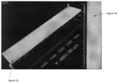
- FIG. 3 a shows a three-dimensional microscopy image of a coating in accordance with the principles of the present invention after performing the step of superfinishing
- FIG. 3 b shows a two-dimensional microscopy image of FIG. 3 a , and further provides a numerical scale to indicate the depth of the pits or pullouts in the coating of FIG. 3 a , which are significantly less in comparison to that of FIG. 2 b and FIG. 1 b;
- FIGS. 4 a , 4 b and 4 c show corresponding images of the superfinished coatings of FIGS. 1 a , 2 a and 3 a , where the presence of dark regions represents pits or pullouts created in the coating after the step of superfinishing;
- FIG. 5 a shows the evaluation length roughness profile
- FIG. 5 b corresponds to FIG. 5 a and shows the Rmr value along the x-axis and the depth of the material along the y-axis.
- the disclosure is set out herein in various embodiments, and with reference to various features and aspects of the invention.
- the disclosure contemplates such features, aspects and embodiments in various permutations and combinations, as being within the scope of the disclosure.
- the disclosure may therefore be specified as comprising, consisting or consisting essentially of, any of such combinations and permutations of these specific features, aspects and embodiments, or a selected one or ones thereof.
- the present invention offers a metallic HVOF coating capable of achieving a desirable surface finish having surface roughness parameters that represent a significant improvement over conventional metallic thermal spray coatings.
- compositions herein are in weight percentage.
- Optimized metallic thermal spray coating as used herein and throughout is intended to mean a thermal spray coating able to achieve desirable surface roughness parameters such that it slides against a hydraulic seal without damaging the surface of the hydraulic seal.
- the present invention relates to a novel coating produced from the pre-alloyed metallic powder that meets surface finished characteristics of carbide coatings.
- the coating finish has been specifically designed to have a combination of five specific roughness parameters consisting of (i) an arithmetical mean roughness designated as (Ra); (ii) a maximum profile peak height designated as (Rp); (iii) a mean roughness depth designated as (Rz); (iv) a degree of skew designated as (Rsk); and (v) a roughness relative material ratio designated as R mr (p,d c ).
- each of the roughness parameters (i), (ii), (iii), (iv) and (v) is maintained at specific values or within a particular range.
- the inventors have discovered that producing a coating that exhibits each of the five roughness parameters at a particular value or within the prescribed range creates an optimized surface profile suitable for sliding against the seal components without damaging the mating seals.
- the finish of the coating translates into minimal damage to the seal by the piston rod surface of a hydraulic system, thereby improving seal integrity and maintaining a leak-free seal between the mating surfaces of the sliding components. In this manner, the present invention offers exceptional seal performance.
- the first surface finishing parameter of the present invention is an arithmetical mean roughness designated as (Ra) between about 2-5 microinches.
- Ra measures the average length between the peaks and valleys and the deviation from the mean line on the entire surface within the sampling length. It is the arithmetic average of all of the absolute values of the profile height deviations from the mean line. Maintaining Ra values within a range of about 2-5 microinches. minimizes the peaks of the coating.
- Ra by itself is not sufficient to properly create an optimized coating finish for hydraulic systems.
- the second surface finishing parameter required is a maximum profile peak height designated as (Rp).
- Rp is no greater than about 8 microinches.
- Rp represents the maximum peak of a surface profile within the sampling length.
- the third surface finishing parameter is a mean roughness depth designated as (Rz).
- Rz represents the average of the vertical distances from the highest peak to the lowest valley that is measured within the sampling lengths.
- the present invention requires the Rz value to be no greater than about 40 microinches.
- the fourth surface finishing parameter is a degree of skew designated as (Rsk).
- Rsk is a numerical indicator of the surface profile that represents the degree of non-symmetry. Rsk is unitless and is required to have a value between about ⁇ 0.1 to ⁇ 3.0, which is indicative of a negative skewness profile.
- a negative skewness profile is generally indicative of a coated surface profile that has more valleys than peaks.
- the fifth surface finishing parameter is a Roughness Relative Material ratio designated as R mr (p,d c ) determined using ISO 21920-2:2021.
- R mr (p,dc) is indicative of the amount of material that is located within a certain depth of the coating material.
- R mr (p,dc) is expressed as a percentage of the material whereby between 70-90% of the material sample is required to be present above a predetermined depth.
- the predetermined depth is determined by traversing down into the material by an amount equal to de from a starting point equal to a value of p, where p represents an amount of topmost material to exclude due to potential false readings.
- P is equal to 5% of the material depth measured from a highest peak.
- De represents the predetermined depth as measured from a starting depth equal to a value of p followed by traversing down into the material by an amount dc that is equal to 0.25*Rz, where Rz is the mean roughness depth described hereinabove.
- Rz is the mean roughness depth described hereinabove.
- the Rmr value between 70-90% ensures there is an adequate amount of material to impart sufficient wear resistance and maintain seal integrity and performance.
- FIG. 5 a shows a surface profile within depth dc. Taking the sum of each of the material lengths designated as Ln along the evaluation length designated as Le and dividing by Le provides the percentage of coating material at depth dc, which represents the vertical distance into the coating material measured from p. In particular, at a depth of dc, FIG. 5 b shows that 80% of the coating material resides above depth dc. Such a relatively high amount of material assists with seal integrity to the hydraulic system.
- FIG. 5 a represents one data point along the curve of FIG. 5 b .
- 5 b graphically is constructed by plotting the evaluation length roughness profile and drawing a horizontal line at various depths from the highest peak. From the depth, the total length as a percentage of evaluation length is calculated. The process is repeated from 0 to 100% and from highest peak to lowest valley as shown in FIGS. 5 a and 5 b.
- the optimized metallic thermal spray coating has a surface that is substantially free of pullouts.
- the powder utilized to produce the coating is pre-alloyed and gas atomized.
- the powder has a particle size distribution defined by a 10 th percentile of the particle size distribution having a diameter of less than or equal to about 5 microns, and a 90 th percentile of the particle size distribution having a diameter of less than or equal to about 13 microns.
- the 50 th percentile of the particle size distribution has a diameter of about 8 microns.
- a modified high velocity oxy-fuel (HVOF) process is utilized to spray the pre-alloyed, gas atomized fine powder.
- oxygen is pre-mixed with an inert gas to produce a diluted oxygen stream.
- the pre-mixing occurs prior to the oxygen entering the combustion chamber of a HVOF thermal spray torch.
- the flow ratio of the inert gas to the oxygen ranges from 8:92 to 50:50, preferably between 10:90 to 30:70 and more preferably between 12:88 to 18:82. Further details for creating the diluted oxygen stream are disclosed in Applicants' application U.S. Patent Pub. No. 2020/0048573, which is incorporated by reference in its entirety for all purposes.
- the diluted oxygen stream After the diluted oxygen stream is created, it is fed into the combustion chamber where it combusts with a suitable hydrocarbon fuel (e.g., kerosene) to generate a flame.
- a suitable hydrocarbon fuel e.g., kerosene
- the pre-alloyed, gas atomized fine powder is then fed into the spray nozzle where it is heated to a molten or semi-molten state.
- the heated powder is directed onto a surface of a sliding hydraulic component to produce an as-deposited coating.
- the as-deposited coating is then superfinished by applying an abrasive film onto the coating at a predetermined abrasive oscillation and pressure.
- the net result is an optimized metallic thermal spray coating having the combination of surface finish parameters discussed.
- the tests utilized pre-alloyed, metallic, gas atomized powders with one of the following particle size distributions (“PSD”) was utilized for each of the tests:
- a pre-alloyed, gas atomized powder having the formulation 42 wt % W, 34 wt % Cr, 20 wt % Co and 4 wt % C was employed to produce a coating onto a test substrate using a conventional High Velocity Oxygen Fuel (“HVOF”) coating process.
- HVOF High Velocity Oxygen Fuel
- Oxygen and kerosene were axially introduced separately into the inlet of the combustion chamber of a commercially available thermal spray HVOF torch made by Praxair TAFA).
- Pre-alloyed gas atomized powder was injected into the spray nozzle.
- the pre-alloyed gas atomized powder had a particle size distribution designated as PSD1 in which a 10 th percentile of the particle size distribution had a diameter of less than or equal to about 25.1 microns and a 90 th percentile of the particle size distribution had a diameter of less or equal to about 53.7 microns.
- the 50 th percentile was 38.1 microns.
- the oxygen gas was not pre-mixed with an inert gas.
- the pre-alloyed gas atomized powder was injected into the spray nozzle. Nitrogen carrier gas was used to convey the pre-alloyed gas atomized powder into the spray nozzle.
- test substrate of 2 inches diameter to be coated was rotating at 900 inch per minute surface speed while the thermal spray torch was traversed across the substrate at 28.6 inches per minute.
- the standoff distance between the torch and part was 15 inches. In this manner, the coating was formed on the test substrate.
- the as-deposited coating was superfinished by applying an abrasive film onto the coating at a predetermined abrasive oscillation and pressure. With the coated substrate rotating, the abrasive film traversed the coating surface in a side-to-side pattern in an attempt to produce the required surface finished pattern.
- the measurements of the superfinished coating were performed with a profilometer stylus, which consisted of a 2-micron radius tip skidded probe.
- Various parameters, such as cutoff length, evaluation length and sampling length were set in accordance with the ISO Standard 4288-1996 to collect the surface roughness measurements.
- the profilometer stylus traversed the coated surface an evaluation length of 0.157 in. to collect the data for purposes of calculating the roughness parameters. In this manner, surface roughness measurements were collected along the evaluation length of the surface of the superfinished coating.
- a cutoff length (i.e., sample length) of 0.032 inches was utilized to filter out roughness waviness of the primary profile of raw data to ensure the remaining data only contained the roughness profile to be captured, as the primary profile may have contained some longer waviness that can interfere with the roughness measurements of interest to be captured in the raw data.
- the results of the superfinishing were Ra: 4.41 ⁇ in; Rp: 6.27 ⁇ in; Rz: 90.8 ⁇ in; Rsk: ⁇ 7.8; and R mr : 96.48%. The measurements indicated that the values for Rz. Rsk, R mr (p,d c ) did not meet the required surface finish criteria.
- FIG. 1 a shows a 3d microscopy image of the superfinished coating.
- FIG. 1 a represents an isometric view of the surface of the superfinished coating to reveal peaks and valleys extending into the coating surface.
- FIG. 1 a illustrates mostly downward needles. The downward needles indicate the number and size of the pits (i.e., the depth of the imperfection) that were created from the superfinishing step.
- FIG. 1 b is a vertical two-dimensional image of FIG. 1 a and provides a numerical scale that corresponds to the size of the valleys or pits of FIG. 2 a .
- FIG. 4 b shows an optical microscopy image of the superfinished coating. The image is intended to show the number and size of any pits that were created after the superfinishing step of the as-deposited coating. The dark regions indicate the pits in the superfinished coating. The pits are indicative of a coating with roughness measurements that did not meet applicable criteria.
- a pre-alloyed, gas atomized powder having the formulation 42 wt % W, 34 wt % Cr, 20 wt % Co and 4 wt % C was employed to produce a coating onto a test substrate using a conventional High Velocity Oxygen Fuel (“HVOF”) coating process.
- HVOF High Velocity Oxygen Fuel
- Oxygen and kerosene fuel were axially introduced separately into the inlet of the combustion chamber of a commercially available thermal spray HVOF torch (Praxair TAFA) and the pre-alloyed gas atomized powder was injected into the spray nozzle.
- the pre-alloyed gas atomized powder had a particle size distribution designated as PSD2 in which a 10 th percentile of the particle size distribution had a diameter of less than or equal to about 12.4 microns and a 90 th percentile of the particle size distribution had a diameter of less or equal to about 24.8 microns.
- the 50 th percentile was 17.1 microns.
- the pre-alloyed gas atomized powder was injected into the spray nozzle. Nitrogen carrier gas was used to convey the pre-alloyed gas atomized powder into the spray nozzle.
- a pre-alloyed, gas atomized powder having the formulation 42 wt % W, 34 wt % Cr, 20 wt % Co and 4 wt % C was employed to produce a coating onto a test substrate using a modified HVOF coating process that pre-mixed oxygen with an inert gas.
- the pre-mixed oxygen and kerosene fuel were axially introduced separately into the inlet of the combustion chamber of a commercially available thermal spray torch (made by Praxair TAFA) and the pre-alloyed gas atomized powder was injected into the spray nozzle.
- the pre-alloyed gas atomized powder designated as PSD2 had a particle size distribution in which a 10 th percentile of the particle size distribution had a diameter of less than or equal to about 12.4 microns and a 90 th percentile of the particle size distribution had a diameter of less or equal to about 24.8 microns.
- the 50 th percentile was 17.1 microns.
- Nitrogen carrier gas was used to convey the pre-alloyed gas atomized powder into the spray nozzle.
- test substrate of 2 inches diameter to be coated was rotating at 2400 inch per minute surface speed while the thermal spray torch was traversed and indexed across the substrate at 76.4 inches per minute.
- the standoff distance between the torch and part was 10 inches. In this manner, the coating was formed on the test substrate.
- the as-deposited coating was superfinished by applying an abrasive film onto the coating at a predetermined abrasive oscillation and pressure. With the coated substrate rotating, the abrasive film traversed the coating surface in a side-to-side pattern to produce the desired surface finish parameters.
- the measurements of the superfinished coating were performed with a profilometer stylus, which consisted of a 2 micron radius tip skidded probe.
- Various parameters, such as cutoff length, evaluation length and sampling length were set in accordance with the ISO Standard 4288-1996 to collect the surface roughness measurements.
- the profilometer stylus traversed the coated surface with an evaluation length of 0.157 in to collect the data for purposes of calculating the roughness parameters. In this manner, surface roughness measurements were collected along the evaluation length of the surface of the superfinished coating.
- a cutoff length of 0.032 inches was utilized to filter out roughness waviness of the primary profile of raw data to ensure the remaining data only contained the roughness profile, as the primary profile may have contained some longer waviness that may have interfered with the roughness measurements of interest in the captured raw data.
- the results of the superfinishing were Ra: 2.61 ⁇ in; Rp: 7.2 ⁇ in; Rz: 64.41 ⁇ in; Rsk: ⁇ 6.261; and R mr (p,d c ): 96.74%. The measurements indicate that the values for Rz, R mr (p,d c ) and Rsk did not meet the required surface finish criteria.
- FIG. 2 a shows a 3d microscopy image of the coating and represents an isometric view of the surface of the superfinished coating to reveal peaks and valleys extending into the coating surface.
- FIG. 2 a illustrates mostly downward needles. The downward needles indicate the number and size of the pits (i.e., the depth of the imperfection) created from the superfinishing step.
- FIG. 2 b is a vertical 2d image of FIG. 2 a and provides a numerical scale that corresponds to the size of the valleys or pits of FIG. 2 a .
- FIGS. 2 a and 2 b show less pits than the coating produced in Comparative Example 1. Specifically, the coating exhibited Rsk and Rz values that were less out of specification than that of Comparative Example 1.
- FIG. 4 b shows an optical microscopy image of the superfinished coating. The images are intended to show the number and size of any pits that were created after the superfinishing step of the as-deposited coating. The dark voids indicate the pits in the superfinished coating. The pits are indicative of a coating with roughness measurements that did not meet applicable criteria.
- FIG. 4 b indicates smaller pits than those created in FIG. 4 a.
- a pre-alloyed, gas atomized powder having the formulation 42 wt % W, 34 wt % Cr. 20 wt % Co and 4 wt % C was employed to produce a coating onto a test substrate using a conventional High Velocity Oxy-Fuel (“HVOF”) coating process.
- HVOF High Velocity Oxy-Fuel
- Oxygen and kerosene fuel were axially introduced separately into the inlet of the combustion chamber of a commercially available thermal spray torch (made by Praxair TAFA) and the pre-alloyed gas atomized powder was injected into the spray nozzle.
- the pre-alloyed gas atomized powder had a particle size distribution in which a 10 th percentile of the particle size distribution had a diameter of less than or equal to about 4.7 microns and a 90 th percentile of the particle size distribution had a diameter of less or equal to about 13.0 microns.
- the 50 th percentile was 7.8 microns.
- the pre-alloyed gas atomized powder was injected into the spray nozzle. Nitrogen carrier gas was used to convey the pre-alloyed gas atomized powder into the spray nozzle.
- the attempt to apply the pre alloyed powder with this particle size distribution through the conventional HVOF thermal spray torch failed as a result of severe powder adherence to the walls of the nozzle. The HVOF process was aborted, and no coating was produced.
- a pre-alloyed, gas atomized powder having the formulation 42 wt % W, 34 wt % Cr. 20 wt % Co and 4 wt % C was employed to produce a coating onto a test substrate using a modified High Velocity Oxy-Fuel (“HVOF”) coating process that pre-mixed oxygen with an inert gas.
- HVOF High Velocity Oxy-Fuel
- the pre-mixed oxygen and kerosene fuel were axially introduced separately into the inlet of the combustion chamber of a commercially available thermal spray torch (made by Praxair TAFA) and the pre-alloyed gas atomized powder was injected into the spray nozzle.
- the pre-alloyed, gas atomized powder had a particle size distribution designated as PSD3 in which a 10 th percentile of the particle size distribution had a diameter of less than or equal to about 4.7 microns and a 90 th percentile of the particle size distribution had a diameter of less than or equal to about 13.0 microns.
- the 50 th percentile was 7.8 microns.
- Nitrogen carrier gas was used to convey the pre-alloyed gas atomized powder into the spray nozzle.
- test substrate of 2 inches diameter to be coated was rotating at 2400 inch per minute surface speed while the thermal spray torch was traversed and indexed across the substrate at 76.4 inches per minute.
- the standoff distance between the torch and part was 10 inches. In this manner, the coating was formed on the test substrate.
- the as-deposited coating was superfinished by applying an abrasive film onto the coating at predetermined abrasive oscillation and pressure. With the coated substrate rotating, the abrasive film traversed the coating surface in a side-to-side pattern in an attempt to produce the required surface finish parameters.
- the measurements of the superfinished coating were performed with a profilometer stylus, which consisted of a 2-micron radius tip skidded probe.
- Various parameters, such as cutoff length, evaluation length and sampling length were set in accordance with the ISO Standard 4288-1996 to collect the surface roughness measurements.
- the profilometer stylus traversed the coated surface an evaluation length of 0.157 inch to collect the data for purposes of calculating the roughness parameters. In this manner, surface roughness measurements were collected along the evaluation length of the surface of the superfinished coating.
- a cutoff length of 0.032 inches was utilized to filter out roughness waviness of the primary profile of raw data to ensure the remaining data only contained the roughness profile, as the primary profile may have contained some longer waviness that may have interfered with the roughness measurements of interest in the captured raw data.
- the results of the superfinishing were Ra: 3.23 ⁇ in; Rp: 6.2 ⁇ in; Rz: 37.49 ⁇ in; Rsk: ⁇ 2.6; and R mr (p,d c ): 87.7%.
- the measurements indicate that each of the surface finish values for Ra, Rp, Rz, Rmr and Rsk met the required surface finish criteria.
- FIG. 3 a shows a three-dimensional microscopy image of the coating and represents an isometric view of the surface of the superfinished coating to reveal peaks and valleys extending into the coating surface.
- FIG. 3 a illustrates less downward needles than those produced in Comparative Example 1 ( FIGS. 1 a and 1 b ) and Comparative Example 3 ( FIGS. 2 a and 2 b ).
- the downward needles indicate the number and size of the pits (i.e., the depth of the imperfection) created from the superfinishing step.
- FIG. 3 b is a vertical two-dimensional image of FIG. 3 a and provides a numerical scale that corresponds to the size of the valleys or pits of FIG. 2 a .
- FIG. 4 c shows an optical microscopy image of the superfinished coating. The images are intended to show the number and size of any pits that were created after the superfinishing step of the as-deposited coating. Virtually no dark regions can be seen. The lack of pits and relatively small size of the pits are indicative of a coating with roughness characteristics that met applicable criteria.
Landscapes
- Chemical & Material Sciences (AREA)
- Engineering & Computer Science (AREA)
- Mechanical Engineering (AREA)
- Physics & Mathematics (AREA)
- Plasma & Fusion (AREA)
- Chemical Kinetics & Catalysis (AREA)
- Materials Engineering (AREA)
- Metallurgy (AREA)
- Organic Chemistry (AREA)
- General Engineering & Computer Science (AREA)
- Combustion & Propulsion (AREA)
- Coating By Spraying Or Casting (AREA)
Abstract
Description
- The present invention generally relates to coatings that are optimized with a surface finish suitable for preventing leakage or without damaging seal components. Particularly, the optimized metallic thermal spray coating has a specific combination of surface roughness parameters, each of which has defined upper limits and/or ranges that produces an exceptional surface finish coating capable of providing improved seal performance over conventional HVOF (High Velocity Oxy-Fuel) metallic coatings.
- Hydraulic systems are used in a variety of applications, including aerospace, construction equipment, agricultural equipment, and other machinery. As part of the hydraulic system, hydraulic cylinders initiate pressure of a fluid and then converts the energy of the fluid into a force that moves the cylinder in a linear direction. The hydraulic cylinder consists of a cylinder barrel, in which a piston connected to a piston rod moves back and forth. Friction between a cylinder rod and its seals can result in wear and has a crucial influence on the efficiency and service life of hydraulic cylinders. Frictional properties of the piston-rod and the seals are becoming increasingly important to the operators of modern fluid-power systems.
- Coatings can be applied to the piston rod and other sliding components. Surface roughness parameters of the finished coating affect frictional characteristics, coating and seal wear, fluid leakage rate, and overall performance of the hydraulic system.
- Traditionally, hard-chrome plating has been applied on hydraulic piston rods and hydraulic cylinders. However, the plating process of hard-chrome contains hexavalent chromium (VI), which is toxic and heavily regulated by the U.S. Environmental Protection Agency (EPA). It is a human carcinogen, and the EPA considers it a hazardous air pollutant under the Clean Air Act, a hazardous substance under the Clean Water Act, and a hazardous waste under the Resource Conservation and Recovery Act. Therefore, the by-products of the plating process are strongly regulated.
- Carbide based coatings applied by HVOF (High Velocity Oxy-Fuel) or other thermal spray processes are used as an alternative for hard chrome plating. However, due to high hardness and typically angular morphology of carbide grains acting like abrasives, such coating can potentially be damaging to the mating surface of polymeric and metallic seals and cause fluid leakage.
- Metallic coatings applied by HVOF, contrary to carbide-based coatings, are more “friendly” against mating seals. Finishing of such coatings presents a certain challenge in that it is difficult to replicate the same surface finish characteristics as can be achieved with conventional carbide-based coatings.
- In view of the above-mentioned drawbacks, there is an unmet need for an improved, environmentally friendly coating suitable for sliding against hydraulic seals which produces comparable wear of the seals to that attained with chrome plate.
- The invention may include any of the following aspects in various combinations and may also include any other aspect of the present invention described below in the written description.
- Other aspects, features and embodiments of the disclosure will be more fully apparent from the ensuing description and appended claims.
- In a first aspect, an optimized metallic thermal spray coating suitable for sliding against—a surface of a hydraulic seal without damaging the surface of the hydraulic seal said optimized metallic thermal spray coating having a measured surface finish defined as a combination of (i) an arithmetical mean roughness designated as (Ra) between about 2-5 microinches; (ii) a maximum profile peak height designated as (Rp) no greater than about 8 microinches; (iii) a mean roughness depth designated as (Rz) no greater than about 40 microinches; (iv) a skewness designated as (Rsk) between about −0.1 to −3.0; and (v) a roughness relative material ratio designated as Rmr(p,dc) determined using ISO 21920-2:2021, wherein Rmr(p,dc) is the percentage of the coating above a predetermined depth, wherein Rmr(p,dc) is between 70-90% of the material above the predetermined depth, wherein p represents an amount of topmost material to exclude due to false readings and has a value equal to p=5% of the material depth measured from a highest peak, and dc represents the predetermined depth as measured from a starting depth equal to a value of p followed by traversing down into the material the predetermined depth by an amount equal to dc, where dc=−0.25*Rz as defined by hydraulic industry standards; said optimized metallic thermal spray coating comprising a high velocity oxygen fuel (HVOF) sprayed gas atomized fine powder, said high velocity oxygen fuel (HVOF) sprayed gas, pre-alloyed atomized fine powder comprising a metallic alloy, said metallic alloy having a particle size distribution where a 10th percentile of the particle size distribution designated as d10 has a diameter of less than or equal to about 5 microns and a 90th percentile of the particle size distribution designated as d90 has a diameter of less than or equal to about 15 microns.
- In a second aspect, a method for creating an optimized metallic thermal spray coating with a desired finish, comprising the step of: providing a gas atomized, pre-alloyed fine powder, said gas atomized, pre-alloyed fine powder comprising a metallic alloy, said metallic alloy having a particle size distribution where a 10th percentile of the particle size distribution has a diameter of less than or equal to about 5 microns, and a 90th percentile of the particle size distribution has a diameter of less than or equal to about 15 microns; providing a sliding component; providing a high velocity oxygen fuel (HVOF) thermal spray torch, said torch comprising a combustion chamber with a nozzle downstream of the combustion chamber; pre-mixing oxygen gas with an inert gas to produce diluted oxygen, wherein the pre-mixing occurs prior to the oxygen gas entering a combustion chamber; introducing the diluted oxygen gas into the combustion chamber; introducing a fuel into the combustion chamber; combusting the fuel with the diluted oxygen gas to generate a flame; introducing the pre-alloyed, gas atomized fine powder into the nozzle; heating the pre-alloyed, gas atomized powder with the flame to produce substantially molten and semi-molten droplets; and directing the substantially molten and semi-molten droplets to a surface of the sliding hydraulic component to produce an as-deposited coating; superfinishing the as-deposited coating to produce the desired surface finish on the coating.
- The objectives and advantages of the invention will be better understood from the following detailed description of the preferred embodiments thereof in connection with the accompanying figures wherein like numbers denote same features throughout and wherein:
-
FIG. 1 a shows a three-dimensional microscopy image of a metallic coating applied using a pre-alloyed metallic powder with powder size distribution (PSD1) and a conventional HVOF coating process after performing the step of superfinishing; -
FIG. 1 b shows a two-dimensional microscopy image ofFIG. 1 a , and further provides a numerical scale to indicate the depth of the pits or pullouts in the coating ofFIG. 1 a; -
FIG. 2 a shows a three-dimensional microscopy of another metallic coating applied using a pre-alloyed metallic powder with powder size distribution (PSD2), and a conventional HVOF coating process after performing the step of superfinishing; -
FIG. 2 b shows a two-dimensional microscopy image ofFIG. 2 a , and further provides numerical scale to indicate the depth of the pits or pullouts in the coating ofFIG. 2 a; -
FIG. 3 a shows a three-dimensional microscopy image of a coating in accordance with the principles of the present invention after performing the step of superfinishing; -
FIG. 3 b shows a two-dimensional microscopy image ofFIG. 3 a , and further provides a numerical scale to indicate the depth of the pits or pullouts in the coating ofFIG. 3 a , which are significantly less in comparison to that ofFIG. 2 b andFIG. 1 b; -
FIGS. 4 a, 4 b and 4 c show corresponding images of the superfinished coatings ofFIGS. 1 a, 2 a and 3 a , where the presence of dark regions represents pits or pullouts created in the coating after the step of superfinishing; and -
FIG. 5 a shows the evaluation length roughness profile; and -
FIG. 5 b corresponds toFIG. 5 a and shows the Rmr value along the x-axis and the depth of the material along the y-axis. - The disclosure is set out herein in various embodiments, and with reference to various features and aspects of the invention. The disclosure contemplates such features, aspects and embodiments in various permutations and combinations, as being within the scope of the disclosure. The disclosure may therefore be specified as comprising, consisting or consisting essentially of, any of such combinations and permutations of these specific features, aspects and embodiments, or a selected one or ones thereof.
- As will be described, the present invention offers a metallic HVOF coating capable of achieving a desirable surface finish having surface roughness parameters that represent a significant improvement over conventional metallic thermal spray coatings.
- Unless indicated otherwise, all compositions herein are in weight percentage.
- The terms “conventional HVOF” and “standard HVOF” are used interchangeably and are intended to mean a thermal spray coating that cannot be superfinished to create the combination of surface roughness parameters described and claimed herein.
- “Optimized metallic thermal spray coating” as used herein and throughout is intended to mean a thermal spray coating able to achieve desirable surface roughness parameters such that it slides against a hydraulic seal without damaging the surface of the hydraulic seal.
- For consistency, it should be understood that all of the surface roughness parameters are expressed in accordance with ISO standards, and surface measurements in the experimental tests described hereinbelow were obtained in accordance with applicable ISO Standard 4288-1996.
- The present invention relates to a novel coating produced from the pre-alloyed metallic powder that meets surface finished characteristics of carbide coatings. As will be discussed, the coating finish has been specifically designed to have a combination of five specific roughness parameters consisting of (i) an arithmetical mean roughness designated as (Ra); (ii) a maximum profile peak height designated as (Rp); (iii) a mean roughness depth designated as (Rz); (iv) a degree of skew designated as (Rsk); and (v) a roughness relative material ratio designated as Rmr(p,dc). As will be discussed hereinbelow, each of the roughness parameters (i), (ii), (iii), (iv) and (v) is maintained at specific values or within a particular range. The inventors have discovered that producing a coating that exhibits each of the five roughness parameters at a particular value or within the prescribed range creates an optimized surface profile suitable for sliding against the seal components without damaging the mating seals. The finish of the coating translates into minimal damage to the seal by the piston rod surface of a hydraulic system, thereby improving seal integrity and maintaining a leak-free seal between the mating surfaces of the sliding components. In this manner, the present invention offers exceptional seal performance.
- The first surface finishing parameter of the present invention is an arithmetical mean roughness designated as (Ra) between about 2-5 microinches. Ra measures the average length between the peaks and valleys and the deviation from the mean line on the entire surface within the sampling length. It is the arithmetic average of all of the absolute values of the profile height deviations from the mean line. Maintaining Ra values within a range of about 2-5 microinches. minimizes the peaks of the coating.
- However, Ra by itself is not sufficient to properly create an optimized coating finish for hydraulic systems. The second surface finishing parameter required is a maximum profile peak height designated as (Rp). Rp is no greater than about 8 microinches. Rp represents the maximum peak of a surface profile within the sampling length.
- The third surface finishing parameter is a mean roughness depth designated as (Rz). Rz represents the average of the vertical distances from the highest peak to the lowest valley that is measured within the sampling lengths. The present invention requires the Rz value to be no greater than about 40 microinches.
- The fourth surface finishing parameter is a degree of skew designated as (Rsk). Rsk is a numerical indicator of the surface profile that represents the degree of non-symmetry. Rsk is unitless and is required to have a value between about −0.1 to −3.0, which is indicative of a negative skewness profile. A negative skewness profile is generally indicative of a coated surface profile that has more valleys than peaks.
- The fifth surface finishing parameter is a Roughness Relative Material ratio designated as Rmr(p,dc) determined using ISO 21920-2:2021. Rmr(p,dc) is indicative of the amount of material that is located within a certain depth of the coating material. Rmr(p,dc) is expressed as a percentage of the material whereby between 70-90% of the material sample is required to be present above a predetermined depth. The predetermined depth is determined by traversing down into the material by an amount equal to de from a starting point equal to a value of p, where p represents an amount of topmost material to exclude due to potential false readings. P is equal to 5% of the material depth measured from a highest peak. De represents the predetermined depth as measured from a starting depth equal to a value of p followed by traversing down into the material by an amount dc that is equal to 0.25*Rz, where Rz is the mean roughness depth described hereinabove. The Rmr value between 70-90% ensures there is an adequate amount of material to impart sufficient wear resistance and maintain seal integrity and performance.
- An illustrative example of an Rmr value that falls between 70-90% in accordance the present invention is shown in
FIG. 5 a andFIG. 5 b .FIG. 5 a shows a surface profile within depth dc. Taking the sum of each of the material lengths designated as Ln along the evaluation length designated as Le and dividing by Le provides the percentage of coating material at depth dc, which represents the vertical distance into the coating material measured from p. In particular, at a depth of dc,FIG. 5 b shows that 80% of the coating material resides above depth dc. Such a relatively high amount of material assists with seal integrity to the hydraulic system.FIG. 5 a represents one data point along the curve ofFIG. 5 b .FIG. 5 b graphically is constructed by plotting the evaluation length roughness profile and drawing a horizontal line at various depths from the highest peak. From the depth, the total length as a percentage of evaluation length is calculated. The process is repeated from 0 to 100% and from highest peak to lowest valley as shown inFIGS. 5 a and 5 b. - The optimized metallic thermal spray coating has a surface that is substantially free of pullouts.
- A method of creating the optimized metallic thermal spray coating will now be described. The powder utilized to produce the coating is pre-alloyed and gas atomized. The powder has a particle size distribution defined by a 10th percentile of the particle size distribution having a diameter of less than or equal to about 5 microns, and a 90th percentile of the particle size distribution having a diameter of less than or equal to about 13 microns. In a preferred embodiment, the 50th percentile of the particle size distribution has a diameter of about 8 microns.
- A modified high velocity oxy-fuel (HVOF) process is utilized to spray the pre-alloyed, gas atomized fine powder. As part of the modified HVOF process, oxygen is pre-mixed with an inert gas to produce a diluted oxygen stream. The pre-mixing occurs prior to the oxygen entering the combustion chamber of a HVOF thermal spray torch. The flow ratio of the inert gas to the oxygen ranges from 8:92 to 50:50, preferably between 10:90 to 30:70 and more preferably between 12:88 to 18:82. Further details for creating the diluted oxygen stream are disclosed in Applicants' application U.S. Patent Pub. No. 2020/0048573, which is incorporated by reference in its entirety for all purposes.
- After the diluted oxygen stream is created, it is fed into the combustion chamber where it combusts with a suitable hydrocarbon fuel (e.g., kerosene) to generate a flame. The pre-alloyed, gas atomized fine powder is then fed into the spray nozzle where it is heated to a molten or semi-molten state. The heated powder is directed onto a surface of a sliding hydraulic component to produce an as-deposited coating. The as-deposited coating is then superfinished by applying an abrasive film onto the coating at a predetermined abrasive oscillation and pressure. The net result is an optimized metallic thermal spray coating having the combination of surface finish parameters discussed.
- The combination of roughness characteristics (i)-(v) with defined upper limits and/or ranges provides an exceptional surface finish coating capable of providing improved seal performance over conventional HVOF carbide based and metallic coatings. The testing in the Comparative Examples 1-4 and Examples validate the superior finishing of the inventive coatings relative to that of conventional metallic thermal spray coatings.
- As will be shown and discussed below in the Working Examples, several experiments were performed to compare the optimized metallic thermal spray coatings of the present invention with conventional HVOF metallic coatings applied from pre-alloyed, gas atomized metallic powders. The criteria for a successful test was dependent upon the coating's ability to satisfy all of the following requirements: (i) an arithmetical mean roughness designated as (Ra) between about 2-5 microinches; (ii) a maximum profile peak height designated as (Rp) no greater than about 8 microinches; (iii) a mean roughness depth designated as (Rz) no greater than about 40 microinches; (iv) a degree of skew designated as (Rsk) between about −0.1 to −3.0; and (v) a roughness relative material ratio designated as Rmr(p,dc) determined using ISO 21920-2:2021, where Rmr(p,dc) is the percentage of the material above a predetermined depth and has a value of 70-90% of the material above the predetermined depth.
- The tests utilized pre-alloyed, metallic, gas atomized powders with one of the following particle size distributions (“PSD”) was utilized for each of the tests:
-
D10 D50 D90 PSD 1 25.1 μm 38.1 μm 53.7 μm PSD 2 12.4 μm 17.1 μm 24.8 μm PSD 3 4.7 μm 7.8 μm 13.0 μm - A pre-alloyed, gas atomized powder having the formulation 42 wt % W, 34 wt % Cr, 20 wt % Co and 4 wt % C was employed to produce a coating onto a test substrate using a conventional High Velocity Oxygen Fuel (“HVOF”) coating process. Oxygen and kerosene were axially introduced separately into the inlet of the combustion chamber of a commercially available thermal spray HVOF torch made by Praxair TAFA). Pre-alloyed gas atomized powder was injected into the spray nozzle. The pre-alloyed gas atomized powder had a particle size distribution designated as PSD1 in which a 10th percentile of the particle size distribution had a diameter of less than or equal to about 25.1 microns and a 90th percentile of the particle size distribution had a diameter of less or equal to about 53.7 microns. The 50th percentile was 38.1 microns. The oxygen gas was not pre-mixed with an inert gas. The pre-alloyed gas atomized powder was injected into the spray nozzle. Nitrogen carrier gas was used to convey the pre-alloyed gas atomized powder into the spray nozzle.
- The test substrate of 2 inches diameter to be coated was rotating at 900 inch per minute surface speed while the thermal spray torch was traversed across the substrate at 28.6 inches per minute. The standoff distance between the torch and part was 15 inches. In this manner, the coating was formed on the test substrate.
- The as-deposited coating was superfinished by applying an abrasive film onto the coating at a predetermined abrasive oscillation and pressure. With the coated substrate rotating, the abrasive film traversed the coating surface in a side-to-side pattern in an attempt to produce the required surface finished pattern.
- After the superfinishing was completed, the measurements of the superfinished coating were performed with a profilometer stylus, which consisted of a 2-micron radius tip skidded probe. Various parameters, such as cutoff length, evaluation length and sampling length were set in accordance with the ISO Standard 4288-1996 to collect the surface roughness measurements. The profilometer stylus traversed the coated surface an evaluation length of 0.157 in. to collect the data for purposes of calculating the roughness parameters. In this manner, surface roughness measurements were collected along the evaluation length of the surface of the superfinished coating. A cutoff length (i.e., sample length) of 0.032 inches was utilized to filter out roughness waviness of the primary profile of raw data to ensure the remaining data only contained the roughness profile to be captured, as the primary profile may have contained some longer waviness that can interfere with the roughness measurements of interest to be captured in the raw data. The results of the superfinishing were Ra: 4.41 μin; Rp: 6.27 μin; Rz: 90.8 μin; Rsk: −7.8; and Rmr: 96.48%. The measurements indicated that the values for Rz. Rsk, Rmr(p,dc) did not meet the required surface finish criteria.
-
FIG. 1 a shows a 3d microscopy image of the superfinished coating.FIG. 1 a represents an isometric view of the surface of the superfinished coating to reveal peaks and valleys extending into the coating surface.FIG. 1 a illustrates mostly downward needles. The downward needles indicate the number and size of the pits (i.e., the depth of the imperfection) that were created from the superfinishing step.FIG. 1 b is a vertical two-dimensional image ofFIG. 1 a and provides a numerical scale that corresponds to the size of the valleys or pits ofFIG. 2 a .FIG. 4 b shows an optical microscopy image of the superfinished coating. The image is intended to show the number and size of any pits that were created after the superfinishing step of the as-deposited coating. The dark regions indicate the pits in the superfinished coating. The pits are indicative of a coating with roughness measurements that did not meet applicable criteria. - A pre-alloyed, gas atomized powder having the formulation 42 wt % W, 34 wt % Cr, 20 wt % Co and 4 wt % C was employed to produce a coating onto a test substrate using a conventional High Velocity Oxygen Fuel (“HVOF”) coating process. Oxygen and kerosene fuel were axially introduced separately into the inlet of the combustion chamber of a commercially available thermal spray HVOF torch (Praxair TAFA) and the pre-alloyed gas atomized powder was injected into the spray nozzle. The pre-alloyed gas atomized powder had a particle size distribution designated as PSD2 in which a 10th percentile of the particle size distribution had a diameter of less than or equal to about 12.4 microns and a 90th percentile of the particle size distribution had a diameter of less or equal to about 24.8 microns. The 50th percentile was 17.1 microns. The pre-alloyed gas atomized powder was injected into the spray nozzle. Nitrogen carrier gas was used to convey the pre-alloyed gas atomized powder into the spray nozzle.
- The attempt to apply the pre alloyed powder with this particle size distribution through the conventional liquid HVOF thermal spray torch failed as a result of severe powder adherence to the walls of the nozzle. The HVOF process was aborted, and no coating was produced.
- A pre-alloyed, gas atomized powder having the formulation 42 wt % W, 34 wt % Cr, 20 wt % Co and 4 wt % C was employed to produce a coating onto a test substrate using a modified HVOF coating process that pre-mixed oxygen with an inert gas. The pre-mixed oxygen and kerosene fuel were axially introduced separately into the inlet of the combustion chamber of a commercially available thermal spray torch (made by Praxair TAFA) and the pre-alloyed gas atomized powder was injected into the spray nozzle. The pre-alloyed gas atomized powder designated as PSD2 had a particle size distribution in which a 10th percentile of the particle size distribution had a diameter of less than or equal to about 12.4 microns and a 90th percentile of the particle size distribution had a diameter of less or equal to about 24.8 microns. The 50th percentile was 17.1 microns. Nitrogen carrier gas was used to convey the pre-alloyed gas atomized powder into the spray nozzle.
- The test substrate of 2 inches diameter to be coated was rotating at 2400 inch per minute surface speed while the thermal spray torch was traversed and indexed across the substrate at 76.4 inches per minute. The standoff distance between the torch and part was 10 inches. In this manner, the coating was formed on the test substrate.
- The as-deposited coating was superfinished by applying an abrasive film onto the coating at a predetermined abrasive oscillation and pressure. With the coated substrate rotating, the abrasive film traversed the coating surface in a side-to-side pattern to produce the desired surface finish parameters.
- After the superfinishing was completed, the measurements of the superfinished coating were performed with a profilometer stylus, which consisted of a 2 micron radius tip skidded probe. Various parameters, such as cutoff length, evaluation length and sampling length were set in accordance with the ISO Standard 4288-1996 to collect the surface roughness measurements. The profilometer stylus traversed the coated surface with an evaluation length of 0.157 in to collect the data for purposes of calculating the roughness parameters. In this manner, surface roughness measurements were collected along the evaluation length of the surface of the superfinished coating. A cutoff length of 0.032 inches was utilized to filter out roughness waviness of the primary profile of raw data to ensure the remaining data only contained the roughness profile, as the primary profile may have contained some longer waviness that may have interfered with the roughness measurements of interest in the captured raw data. The results of the superfinishing were Ra: 2.61 μin; Rp: 7.2 μin; Rz: 64.41 μin; Rsk: −6.261; and Rmr(p,dc): 96.74%. The measurements indicate that the values for Rz, Rmr(p,dc) and Rsk did not meet the required surface finish criteria.
-
FIG. 2 a shows a 3d microscopy image of the coating and represents an isometric view of the surface of the superfinished coating to reveal peaks and valleys extending into the coating surface.FIG. 2 a illustrates mostly downward needles. The downward needles indicate the number and size of the pits (i.e., the depth of the imperfection) created from the superfinishing step.FIG. 2 b is a vertical 2d image ofFIG. 2 a and provides a numerical scale that corresponds to the size of the valleys or pits ofFIG. 2 a . Collectively,FIGS. 2 a and 2 b show less pits than the coating produced in Comparative Example 1. Specifically, the coating exhibited Rsk and Rz values that were less out of specification than that of Comparative Example 1. However, the size and number of the pits in the coating remained unacceptably high and caused the coating to not meet the applicable criteria for surface roughness measurement.FIG. 4 b shows an optical microscopy image of the superfinished coating. The images are intended to show the number and size of any pits that were created after the superfinishing step of the as-deposited coating. The dark voids indicate the pits in the superfinished coating. The pits are indicative of a coating with roughness measurements that did not meet applicable criteria.FIG. 4 b indicates smaller pits than those created inFIG. 4 a. - A pre-alloyed, gas atomized powder having the formulation 42 wt % W, 34 wt % Cr. 20 wt % Co and 4 wt % C was employed to produce a coating onto a test substrate using a conventional High Velocity Oxy-Fuel (“HVOF”) coating process. Oxygen and kerosene fuel were axially introduced separately into the inlet of the combustion chamber of a commercially available thermal spray torch (made by Praxair TAFA) and the pre-alloyed gas atomized powder was injected into the spray nozzle. The pre-alloyed gas atomized powder had a particle size distribution in which a 10th percentile of the particle size distribution had a diameter of less than or equal to about 4.7 microns and a 90th percentile of the particle size distribution had a diameter of less or equal to about 13.0 microns. The 50th percentile was 7.8 microns. The pre-alloyed gas atomized powder was injected into the spray nozzle. Nitrogen carrier gas was used to convey the pre-alloyed gas atomized powder into the spray nozzle. The attempt to apply the pre alloyed powder with this particle size distribution through the conventional HVOF thermal spray torch failed as a result of severe powder adherence to the walls of the nozzle. The HVOF process was aborted, and no coating was produced.
- A pre-alloyed, gas atomized powder having the formulation 42 wt % W, 34 wt % Cr. 20 wt % Co and 4 wt % C was employed to produce a coating onto a test substrate using a modified High Velocity Oxy-Fuel (“HVOF”) coating process that pre-mixed oxygen with an inert gas. The pre-mixed oxygen and kerosene fuel were axially introduced separately into the inlet of the combustion chamber of a commercially available thermal spray torch (made by Praxair TAFA) and the pre-alloyed gas atomized powder was injected into the spray nozzle. The pre-alloyed, gas atomized powder had a particle size distribution designated as PSD3 in which a 10th percentile of the particle size distribution had a diameter of less than or equal to about 4.7 microns and a 90th percentile of the particle size distribution had a diameter of less than or equal to about 13.0 microns. The 50th percentile was 7.8 microns. Nitrogen carrier gas was used to convey the pre-alloyed gas atomized powder into the spray nozzle.
- The test substrate of 2 inches diameter to be coated was rotating at 2400 inch per minute surface speed while the thermal spray torch was traversed and indexed across the substrate at 76.4 inches per minute. The standoff distance between the torch and part was 10 inches. In this manner, the coating was formed on the test substrate.
- The as-deposited coating was superfinished by applying an abrasive film onto the coating at predetermined abrasive oscillation and pressure. With the coated substrate rotating, the abrasive film traversed the coating surface in a side-to-side pattern in an attempt to produce the required surface finish parameters.
- After the surface finishing was completed, the measurements of the superfinished coating were performed with a profilometer stylus, which consisted of a 2-micron radius tip skidded probe. Various parameters, such as cutoff length, evaluation length and sampling length were set in accordance with the ISO Standard 4288-1996 to collect the surface roughness measurements. The profilometer stylus traversed the coated surface an evaluation length of 0.157 inch to collect the data for purposes of calculating the roughness parameters. In this manner, surface roughness measurements were collected along the evaluation length of the surface of the superfinished coating. A cutoff length of 0.032 inches was utilized to filter out roughness waviness of the primary profile of raw data to ensure the remaining data only contained the roughness profile, as the primary profile may have contained some longer waviness that may have interfered with the roughness measurements of interest in the captured raw data. The results of the superfinishing were Ra: 3.23 μin; Rp: 6.2 μin; Rz: 37.49 μin; Rsk: −2.6; and Rmr(p,dc): 87.7%. The measurements indicate that each of the surface finish values for Ra, Rp, Rz, Rmr and Rsk met the required surface finish criteria.
-
FIG. 3 a shows a three-dimensional microscopy image of the coating and represents an isometric view of the surface of the superfinished coating to reveal peaks and valleys extending into the coating surface.FIG. 3 a illustrates less downward needles than those produced in Comparative Example 1 (FIGS. 1 a and 1 b ) and Comparative Example 3 (FIGS. 2 a and 2 b ). The downward needles indicate the number and size of the pits (i.e., the depth of the imperfection) created from the superfinishing step.FIG. 3 b is a vertical two-dimensional image ofFIG. 3 a and provides a numerical scale that corresponds to the size of the valleys or pits ofFIG. 2 a . Collectively,FIGS. 3 a and 3 b show a reduced number of pits and smaller sized pits in comparison to the superfinished coatings produced in Comparative Example 1 and Comparative Example 3.FIG. 4 c shows an optical microscopy image of the superfinished coating. The images are intended to show the number and size of any pits that were created after the superfinishing step of the as-deposited coating. Virtually no dark regions can be seen. The lack of pits and relatively small size of the pits are indicative of a coating with roughness characteristics that met applicable criteria. - While it has been shown and described what is considered to be certain embodiments of the invention, it will, of course, be understood that various modifications and changes in form or detail can readily be made without departing from the spirit and scope of the invention. It is, therefore, intended that this invention not be limited to the exact form and detail herein shown and described. nor to anything less than the whole of the invention herein disclosed and hereinafter claimed.
Claims (9)
Priority Applications (4)
| Application Number | Priority Date | Filing Date | Title |
|---|---|---|---|
| US18/334,782 US20240417841A1 (en) | 2023-06-14 | 2023-06-14 | Coating for hydraulic rods and other sliding components and method of producing the same |
| EP24734568.9A EP4728109A1 (en) | 2023-06-14 | 2024-05-22 | Coating for hydraulic rods and other sliding components and method of producing the same |
| PCT/US2024/030508 WO2024258571A1 (en) | 2023-06-14 | 2024-05-22 | Coating for hydraulic rods and other sliding components and method of producing the same |
| KR1020267000852A KR20260021761A (en) | 2023-06-14 | 2024-05-22 | Coatings for hydraulic rods and other sliding components and methods for producing them |
Applications Claiming Priority (1)
| Application Number | Priority Date | Filing Date | Title |
|---|---|---|---|
| US18/334,782 US20240417841A1 (en) | 2023-06-14 | 2023-06-14 | Coating for hydraulic rods and other sliding components and method of producing the same |
Publications (1)
| Publication Number | Publication Date |
|---|---|
| US20240417841A1 true US20240417841A1 (en) | 2024-12-19 |
Family
ID=91585412
Family Applications (1)
| Application Number | Title | Priority Date | Filing Date |
|---|---|---|---|
| US18/334,782 Pending US20240417841A1 (en) | 2023-06-14 | 2023-06-14 | Coating for hydraulic rods and other sliding components and method of producing the same |
Country Status (4)
| Country | Link |
|---|---|
| US (1) | US20240417841A1 (en) |
| EP (1) | EP4728109A1 (en) |
| KR (1) | KR20260021761A (en) |
| WO (1) | WO2024258571A1 (en) |
Citations (2)
| Publication number | Priority date | Publication date | Assignee | Title |
|---|---|---|---|---|
| CN110480424A (en) * | 2019-08-13 | 2019-11-22 | 中国航空工业集团公司西安飞行自动控制研究所 | Process for HVOF-enhanced Surface Finishing of Actuator Pistons |
| US11965251B2 (en) * | 2018-08-10 | 2024-04-23 | Praxair S.T. Technology, Inc. | One-step methods for creating fluid-tight, fully dense coatings |
Family Cites Families (2)
| Publication number | Priority date | Publication date | Assignee | Title |
|---|---|---|---|---|
| US6004372A (en) * | 1999-01-28 | 1999-12-21 | Praxair S.T. Technology, Inc. | Thermal spray coating for gates and seats |
| EP3615640B1 (en) | 2017-04-27 | 2024-12-18 | The Lubrizol Corporation | Method of lubricating a mechanical device with high pyrophosphate level lubricant |
-
2023
- 2023-06-14 US US18/334,782 patent/US20240417841A1/en active Pending
-
2024
- 2024-05-22 KR KR1020267000852A patent/KR20260021761A/en active Pending
- 2024-05-22 WO PCT/US2024/030508 patent/WO2024258571A1/en not_active Ceased
- 2024-05-22 EP EP24734568.9A patent/EP4728109A1/en active Pending
Patent Citations (2)
| Publication number | Priority date | Publication date | Assignee | Title |
|---|---|---|---|---|
| US11965251B2 (en) * | 2018-08-10 | 2024-04-23 | Praxair S.T. Technology, Inc. | One-step methods for creating fluid-tight, fully dense coatings |
| CN110480424A (en) * | 2019-08-13 | 2019-11-22 | 中国航空工业集团公司西安飞行自动控制研究所 | Process for HVOF-enhanced Surface Finishing of Actuator Pistons |
Also Published As
| Publication number | Publication date |
|---|---|
| WO2024258571A9 (en) | 2026-02-05 |
| EP4728109A1 (en) | 2026-04-22 |
| WO2024258571A1 (en) | 2024-12-19 |
| KR20260021761A (en) | 2026-02-13 |
Similar Documents
| Publication | Publication Date | Title |
|---|---|---|
| Vasudev et al. | Erosion behaviour of HVOF sprayed Alloy718-nano Al2O3 composite coatings on grey cast iron at elevated temperature conditions | |
| KR101718840B1 (en) | Sliding member having a thermally sprayed coating and method for producing same | |
| US10689743B2 (en) | Piston ring | |
| EP2933535B1 (en) | Piston ring with sprayed coating and method for producing piston ring with sprayed coating | |
| US20090283611A1 (en) | Surface treatments and coatings for atomization | |
| SE526708C2 (en) | Methods of making a abrasion resistant hot-sprayed coating for a slider | |
| US20240417841A1 (en) | Coating for hydraulic rods and other sliding components and method of producing the same | |
| Tillmann et al. | Influence of handling parameters on coating characteristics in order to produce near-net-shape wear resistant coatings | |
| EP2395123A1 (en) | Composition and method for applying a protective coating | |
| DK3141628T3 (en) | Sliding element and piston ring | |
| de Villiers Lovelock et al. | Characterisation of WC—12Co thermal spray powders and HPHVOF wear resistant coatings | |
| Picas et al. | The influence of heat treatment on tribological and mechanical properties of HVOF sprayed CrC–NiCr coatings | |
| Uzun et al. | Investigation of wear behaviour of HVOF sprayed WC-Co coatings for automotive parts in different working conditions | |
| Cinca et al. | Characterization of the microstructure, mechanical properties and corrosion behaviour of submicron WC-12Co coatings produced by CGS and HVAF compared with sintered bulk material | |
| Hauer et al. | Novel Fe-and Ni-Based HVOF-Sprayed Coatings Compared to APS-Sprayed TBC Systems for Improved Thermal Insulation Capabilities in Cryogenic Environments | |
| Vaz et al. | Improving the Wear and Corrosion Resistance of Maraging Part Obtained by Cold Gas Spray Additive Manufacturing. Metals 2021, 11, 1092 | |
| Ma et al. | Study on the Friction Performance of Cerium Oxide on Supersonic Flame-Sprayed WC-10Co-4Cr Coating. Coatings 2021, 11, 24 | |
| Bastidas et al. | Comparative study of jet slurry erosion of martensitic stainless steel with tungsten carbide HVOF coating | |
| CN118996312A (en) | Self-lubricating hard alloy coating and preparation process thereof | |
| Ma et al. | Ultra-smooth hardface coatings applied by advanced HVOF process | |
| Xu | Fabrication of Superhydrophobic Ceramic Coatings via Solution Precursor Plasma Spray Process under Atmospheric and Low-pressure Conditions | |
| Tillmann et al. | Near-net-shape and dense wear resistant thermally sprayed coatings | |
| Thirugnanasambantham et al. | High-Temperature Erosion and its Mechanisms of Hastelloy X Superalloy under Hot Air Jet Conditions | |
| McDonald et al. | Development of Processing Windows for HVOF Carbide-Based Coatings | |
| Imeson | Erosion Resistance of High Velocity Oxy-Fuel WC-Co-Cr Thermal Spray Coatings |
Legal Events
| Date | Code | Title | Description |
|---|---|---|---|
| AS | Assignment |
Owner name: PRAXAIR S.T. TECHNOLOGY, INC., CONNECTICUT Free format text: ASSIGNMENT OF ASSIGNORS INTEREST;ASSIGNORS:KLEYMAN, ARDY S.;SMITH, ADAM J.;WANG, DAMING;AND OTHERS;SIGNING DATES FROM 20230618 TO 20230619;REEL/FRAME:063986/0602 |
|
| STPP | Information on status: patent application and granting procedure in general |
Free format text: DOCKETED NEW CASE - READY FOR EXAMINATION |
|
| STPP | Information on status: patent application and granting procedure in general |
Free format text: NON FINAL ACTION MAILED |
|
| STPP | Information on status: patent application and granting procedure in general |
Free format text: RESPONSE TO NON-FINAL OFFICE ACTION ENTERED AND FORWARDED TO EXAMINER |
|
| STPP | Information on status: patent application and granting procedure in general |
Free format text: RESPONSE TO NON-FINAL OFFICE ACTION ENTERED AND FORWARDED TO EXAMINER |
|
| STPP | Information on status: patent application and granting procedure in general |
Free format text: NON FINAL ACTION COUNTED, NOT YET MAILED |
|
| STPP | Information on status: patent application and granting procedure in general |
Free format text: NON FINAL ACTION MAILED |