US20240297463A1 - Connector assembly - Google Patents
Connector assembly Download PDFInfo
- Publication number
- US20240297463A1 US20240297463A1 US18/438,525 US202418438525A US2024297463A1 US 20240297463 A1 US20240297463 A1 US 20240297463A1 US 202418438525 A US202418438525 A US 202418438525A US 2024297463 A1 US2024297463 A1 US 2024297463A1
- Authority
- US
- United States
- Prior art keywords
- heat sink
- latching
- wall
- sink bracket
- shielding cage
- Prior art date
- Legal status (The legal status is an assumption and is not a legal conclusion. Google has not performed a legal analysis and makes no representation as to the accuracy of the status listed.)
- Pending
Links
Images


Classifications
-
- H—ELECTRICITY
- H01—ELECTRIC ELEMENTS
- H01R—ELECTRICALLY-CONDUCTIVE CONNECTIONS; STRUCTURAL ASSOCIATIONS OF A PLURALITY OF MUTUALLY-INSULATED ELECTRICAL CONNECTING ELEMENTS; COUPLING DEVICES; CURRENT COLLECTORS
- H01R12/00—Structural associations of a plurality of mutually-insulated electrical connecting elements, specially adapted for printed circuits, e.g. printed circuit boards [PCB], flat or ribbon cables, or like generally planar structures, e.g. terminal strips, terminal blocks; Coupling devices specially adapted for printed circuits, flat or ribbon cables, or like generally planar structures; Terminals specially adapted for contact with, or insertion into, printed circuits, flat or ribbon cables, or like generally planar structures
- H01R12/70—Coupling devices
- H01R12/71—Coupling devices for rigid printing circuits or like structures
- H01R12/72—Coupling devices for rigid printing circuits or like structures coupling with the edge of the rigid printed circuits or like structures
- H01R12/721—Coupling devices for rigid printing circuits or like structures coupling with the edge of the rigid printed circuits or like structures cooperating directly with the edge of the rigid printed circuits
-
- H—ELECTRICITY
- H05—ELECTRIC TECHNIQUES NOT OTHERWISE PROVIDED FOR
- H05K—PRINTED CIRCUITS; CASINGS OR CONSTRUCTIONAL DETAILS OF ELECTRIC APPARATUS; MANUFACTURE OF ASSEMBLAGES OF ELECTRICAL COMPONENTS
- H05K7/00—Constructional details common to different types of electric apparatus
- H05K7/20—Modifications to facilitate cooling, ventilating, or heating
- H05K7/2039—Modifications to facilitate cooling, ventilating, or heating characterised by the heat transfer by conduction from the heat generating element to a dissipating body
-
- H—ELECTRICITY
- H01—ELECTRIC ELEMENTS
- H01R—ELECTRICALLY-CONDUCTIVE CONNECTIONS; STRUCTURAL ASSOCIATIONS OF A PLURALITY OF MUTUALLY-INSULATED ELECTRICAL CONNECTING ELEMENTS; COUPLING DEVICES; CURRENT COLLECTORS
- H01R12/00—Structural associations of a plurality of mutually-insulated electrical connecting elements, specially adapted for printed circuits, e.g. printed circuit boards [PCB], flat or ribbon cables, or like generally planar structures, e.g. terminal strips, terminal blocks; Coupling devices specially adapted for printed circuits, flat or ribbon cables, or like generally planar structures; Terminals specially adapted for contact with, or insertion into, printed circuits, flat or ribbon cables, or like generally planar structures
- H01R12/70—Coupling devices
- H01R12/71—Coupling devices for rigid printing circuits or like structures
- H01R12/712—Coupling devices for rigid printing circuits or like structures co-operating with the surface of the printed circuit or with a coupling device exclusively provided on the surface of the printed circuit
-
- H—ELECTRICITY
- H01—ELECTRIC ELEMENTS
- H01R—ELECTRICALLY-CONDUCTIVE CONNECTIONS; STRUCTURAL ASSOCIATIONS OF A PLURALITY OF MUTUALLY-INSULATED ELECTRICAL CONNECTING ELEMENTS; COUPLING DEVICES; CURRENT COLLECTORS
- H01R13/00—Details of coupling devices of the kinds covered by groups H01R12/70 or H01R24/00 - H01R33/00
- H01R13/46—Bases; Cases
- H01R13/502—Bases; Cases composed of different pieces
- H01R13/506—Bases; Cases composed of different pieces assembled by snap action of the parts
-
- H—ELECTRICITY
- H01—ELECTRIC ELEMENTS
- H01R—ELECTRICALLY-CONDUCTIVE CONNECTIONS; STRUCTURAL ASSOCIATIONS OF A PLURALITY OF MUTUALLY-INSULATED ELECTRICAL CONNECTING ELEMENTS; COUPLING DEVICES; CURRENT COLLECTORS
- H01R13/00—Details of coupling devices of the kinds covered by groups H01R12/70 or H01R24/00 - H01R33/00
- H01R13/648—Protective earth or shield arrangements on coupling devices, e.g. anti-static shielding
- H01R13/658—High frequency shielding arrangements, e.g. against EMI [Electro-Magnetic Interference] or EMP [Electro-Magnetic Pulse]
- H01R13/6581—Shield structure
- H01R13/6582—Shield structure with resilient means for engaging mating connector
-
- H—ELECTRICITY
- H05—ELECTRIC TECHNIQUES NOT OTHERWISE PROVIDED FOR
- H05K—PRINTED CIRCUITS; CASINGS OR CONSTRUCTIONAL DETAILS OF ELECTRIC APPARATUS; MANUFACTURE OF ASSEMBLAGES OF ELECTRICAL COMPONENTS
- H05K7/00—Constructional details common to different types of electric apparatus
- H05K7/20—Modifications to facilitate cooling, ventilating, or heating
- H05K7/2039—Modifications to facilitate cooling, ventilating, or heating characterised by the heat transfer by conduction from the heat generating element to a dissipating body
- H05K7/20409—Outer radiating structures on heat dissipating housings, e.g. fins integrated with the housing
- H05K7/20418—Outer radiating structures on heat dissipating housings, e.g. fins integrated with the housing the radiating structures being additional and fastened onto the housing
Definitions
- the present disclosure relates to a connector assembly, and particularly relates to a connector assembly which has a heat sink.
- Cipheral patent document CN114623722A discloses a heat sink module which includes a heat dissipating member, pressure applying elastic members, a lever member and supporting elastic members.
- the heat sink module is entirely accommodated in an upper heat sink bracket, the lever member is pivoted to the upper heat sink bracket, the lever member is used to downwardly apply a pressure to the pressure applying elastic members, the pressure applying elastic members push the heat dissipating member to move downwardly, after an acting force of the lever member is released, the supporting elastic members are used to elastically support the heat dissipating member to move upwardly.
- an object of the present disclosure is to provide a connector assembly which can improve at least one problem of prior art.
- a connector assembly of the present disclosure comprises a guide shielding cage, a heat sink bracket and at least two heat sink modules.
- the guide shielding cage comprises a top wall, two side walls, a partitioning wall which is positioned between the two side walls, and at least two mating channels which are sideward arranged side by side and are partitioned by the partitioning wall.
- the heat sink bracket is assembled to the top wall of the guide shielding cage, the partitioning wall of the guide shielding cage extends into the heat sink bracket to constitute at least two accommodating cavities which correspond to the at least two mating channels, the partitioning wall has a first wall portion which is positioned in the guide shielding cage and a second wall portion which is positioned in the heat sink bracket, the partitioning wall and the heat sink bracket are therebetween assembled by a first assembling construction, the heat sink bracket and the top wall of the guide shielding cage are assembled by a second assembling construction.
- the at least two heat sink modules are respectively assembled in the at least two accommodating cavities of the heat sink bracket.
- the first assembling construction comprises a lower latching construction which is between the second wall portion of the partitioning wall and a bottom plate of the heat sink bracket and an upper latching construction which is between the second wall portion of the partitioning wall and a top plate of the heat sink bracket.
- the lower latching construction comprises a forward extending latch piece and a rearward extending latch piece, the forward extending latch piece extends forwardly from the second wall portion and is used to latch with the bottom plate of the heat sink bracket, the rearward extending latch piece extends rearwardly from the second wall portion, sideward bends offset and is used to latch with the bottom plate of the heat sink bracket;
- the upper latching construction comprises an upper latching piece which extends upwardly from an upper edge of the second wall portion and is used to pass through a latching slit formed to the top plate to latch with the top plate of the heat sink bracket.
- the lower latching construction further comprises a pair of bendable latching pieces which are between the forward extending latch piece and the rearward extending latch piece and are used to latch with the bottom plate of the heat sink bracket.
- the top plate is further formed with a depressed portion which is depressed downwardly, the latching slit of the top plate is formed to a bottom portion of the depressed portion, the upper latching piece of the upper latching construction passes through the latching slit of the top plate and is positioned in the depressed portion.
- the second assembling construction comprises a side latching construction which is between a left side and right side of a bottom plate of the heat sink bracket and a left side and right side of the top wall of the guide shielding cage, a side plate latching construction which is between side plates of the heat sink bracket and the two side walls of the guide shielding cage, and a rear latching construction which is between a rear end of the bottom plate of the heat sink bracket and the top wall of the guide shielding cage.
- the side latching construction comprises a snapping piece which extends out of the top wall and a protruding piece which extends sideward from the bottom plate of the heat sink bracket, the snapping piece has a snapping groove which is opened forwardly and is used to snap the protruding piece of the heat sink bracket.
- the side plate latching construction comprises inserting pieces which extend from the side plates of the heat sink bracket to outer sides of the side wall of the guide shielding cage and protrude rearwardly, bulges which are formed to the side walls, and inserting holes which are constructed to the bulges and are opened forwardly, the inserting pieces are used to rearwardly insert into the inserting holes.
- the rear latching construction comprises a rear latching piece which extends downwardly from a rear end of the bottom plate of the heat sink bracket and a rear latching groove which is formed to the top wall of the guide shielding cage, the rear latching piece is used to downwardly latch to the rear latching groove.
- the second assembling construction further comprises a sideward limiting-position construction which is between two sides of the bottom plate of the heat sink bracket and the two side walls of the guide shielding cage.
- the sideward limiting-position construction comprises side limiting-position pieces which bend downwardly from rear ends of the two sides of the bottom plate of the heat sink bracket and extend, the side limiting-position pieces are respectively positioned at outer side surfaces of the two side walls of the guide shielding cage.
- the heat sink module comprises a heat sink, force applying springs, a rotatable member and supporting springs; the rotatable member acts to the force applying springs, the force applying springs downwardly act to the heat sink, the supporting springs elastically upwardly support the heat sink.
- the rotatable member of the heat sink module has pivoting shafts
- the pivoting shafts of the rotatable members of the two adjacent heat sink modules are front and rear staggered
- the second wall portion of the partitioning wall has two pivoting holes which are front and rear staggered and are used to be respectively pivoted with the pivoting shafts of the two adjacent rotatable members.
- the at least two accommodating cavities of the heat sink bracket are respectively used to accommodate the at least two heat sink modules, and the guide shielding cage and the heat sink bracket share the partitioning wall(s).
- the partitioning wall(s) and the heat sink bracket are therebetween assembled by the first assembling construction, the heat sink bracket and the top wall of the guide shielding cage are assembled by the second assembling construction, so the heat sink bracket is capable of being firmly assembled on the guide shielding cage.
- the pivoting shafts of the adjacent two rotatable members of the heat sink modules are front and rear staggered, so the adjacent two rotatable members are capable of being pivoted to the same partitioning wall.
- FIG. 1 is a perspective view of an embodiment of a connector assembly of the present disclosure, a circuit board and a pluggable module;
- FIG. 2 is a perspective exploded view of the embodiment
- FIG. 3 is a further perspective exploded view of the embodiment
- FIG. 4 is a perspective exploded view of a guide shielding cage of the embodiment
- FIG. 5 is a perspective view of the guide shielding cage and a heat sink bracket of the embodiment
- FIG. 6 is a perspective view of the guide shielding cage and the heat sink bracket of the embodiment viewed from another angle;
- FIG. 7 is a partially enlarged perspective view of a region A of FIG. 5 illustrating a lower latching construction and an upper latching construction of a first assembling construction of the embodiment;
- FIG. 8 is a partially enlarged perspective view of a region B of FIG. 6 illustrating the lower latching construction and the upper latching construction of the first assembling construction and a rear latching construction of a second assembling construction of the embodiment;
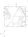
- FIG. 9 is a partially enlarged perspective view of a region C of FIG. 5 illustrating a side latching construction of the second assembling construction of the embodiment
- FIG. 10 is a partially enlarged perspective view of a region D of FIG. 5 illustrating a side plate latching construction and a sideward limiting-position construction of the second assembling construction of the embodiment;
- FIG. 11 is a perspective exploded view of the heat sink bracket and heat sink modules of the embodiment.
- FIG. 12 is a perspective exploded view of the heat sink bracket and the heat sink modules of the embodiment viewed from another angle.
- an embodiment of a connector assembly 100 of the present disclosure is adapted to be provided on a circuit board 200 , and is adapted to mate with a pluggable module 300 .
- the pluggable module 300 has a shell member 301 , a mating circuit board 302 and a cable 303 .
- the shell member 301 has an inserting portion 301 a
- the mating circuit board 302 is provided to a front end of the inserting portion 301 a
- the cable 303 is provided to a rear end of the shell member 301 and is electrically connected to the mating circuit board 302 .
- the connector assembly 100 includes a guide shielding cage 1 , three receptacle connectors 2 , a heat sink bracket 3 and three heat sink modules 4 . It is noted that, the number of the receptacle connectors 2 corresponds to the number of the heat sink modules 4 , in other implementing manners, the number of the receptacle connector 2 and the number of the heat sink module 4 also each may be two or more, and thus are not limited to the present embodiment.
- the guide shielding cage 1 is for example formed by processing, such as stamping and bending, a metal thin plate via a mold, the guide shielding cage 1 is used to be provided to the circuit board 200 .
- the guide shielding cage 1 has a top wall 11 and a bottom wall 12 which are spaced apart from each other along an up-down direction D 1 (a direction to which an arrow points is up, and an opposite direction is down), two side walls 13 which are spaced apart from each other along a left-right direction D 2 (a direction to which an arrow points is right, and an opposite direction is left), two partitioning walls 14 which are positioned between the two side walls 13 , a rear wall 15 which is positioned to a rear end of the guide shielding cage 1 along a front-rear direction D 3 (a direction to which an arrow points is front, and an opposite direction is rear), three mating channels 16 which are left and right sideward arranged side by side, are positioned inside the guide shielding cage 1 and are partitioned by the two partitioning walls 14 , and
- Each mating channel 16 has a front end inserting port 161 which is toward the front and allows the inserting portion 301 a of the pluggable module 300 to insert therein and a bottom opening 162 which is positioned at a rear of a bottom portion of the mating channel 16 .
- the number of the partitioning wall 14 also may be one or more, and the number of the mating channels 16 also may be two or more according to the different number of the partitioning wall 14 , which is not limited to the present embodiment.
- the top wall 11 of the guide shielding cage 1 has windows 111 which are respectively communicated with the mating channels 16 , first slits 112 which are positioned between the mating channels 16 and front and rear extend, guiding portions 113 which each extend downwardly from a rear segment of a side of the corresponding window 111 into the corresponding mating channel 16 , and stopping portions 114 which each extend downwardly from a rear end of the corresponding window 111 into the corresponding mating channel 16 .
- Each side wall 13 of the guide shielding cage 1 has an inward extending elastic piece 131 which is positioned in the front of the side wall 13 and extends into the adjacent mating channel 16 .
- Each partitioning wall 14 of the guide shielding cage 1 has two inward extending elastic pieces 141 which are positioned in the front of the partitioning wall 14 and respectively extend into the two adjacent mating channels 16 .
- Ground members 17 are assembled around the front end inserting ports 161 of the mating channels 16 of the guide shielding cage 1 .
- the guide shielding cage 1 of the connector assembly 100 may be provided to a mounting hole (not shown) of a casing (not shown), each ground member 17 has a plurality of elastic portions 171 which extend rearwardly and are distributed to an outer side and an inner side of the guide shielding cage 1 , the elastic portion 171 which is positioned at the outer side of the guide shielding cage 1 is used to contact a peripheral part of the mounting hole of the casing, the elastic portion 171 which is positioned at the inner side of the guide shielding cage 1 is used to contact the pluggable module 300 .
- the receptacle connectors 2 are used to be arranged side by side along the left-right direction D 2 and be provided on the circuit board 200 , the receptacle connectors 2 each are received in a rear segment of the corresponding mating channel 16 via the bottom opening 162 of the corresponding mating channel 16 of the guide shielding cage 1 .
- Each receptacle connector 2 has a housing 21 which is insulative and a plurality of terminals 22 which are provided to the housing 21 .
- the housing 21 has a mating slot 211 which allows the mating circuit board 302 of the pluggable module 300 to insert therein, each terminal 22 has a contact portion 221 which is positioned in the mating slot 211 and a tail portion (not shown) which extends downwardly out of a bottom portion of the housing 21 , the tail portions of the plurality of terminals 22 are respectively used to be soldered to pads (not shown) on the circuit board 200 so as to connect conductive traces (not shown) on the circuit board 200 .
- the inserting portion 301 a of the pluggable module 300 has two locking recessed grooves 301 b which are respectively positioned at a left side and a right side of the inserting portion 301 a , a guiding groove structure 301 c which is positioned to a top portion of the front end of the inserting portion 301 a , and an aligning structure 301 d which is positioned a top portion of the inserting portion 301 a .
- the inward extending elastic pieces 131 of the two side walls 13 and the inward extending elastic pieces 141 of the partitioning walls 14 of the guide shielding cage 1 are used to cooperate with the two locking recessed grooves 301 b of the pluggable module 300 which inserts into the corresponding mating channel 16 , so as to generate a locking effect.
- the guiding portion 113 is used to insert into the guiding groove structure 301 c of the pluggable module 300 so as to generate a guiding function.
- the stopping portion 114 is used to stop the aligning structure 301 d of the pluggable module 300 so as to limit an inserting position of the pluggable module 300 .
- the pluggable module 300 further has a locking release member 304 , when the locking release member 304 is pulled, the inward extending elastic piece 131 and the inward extending elastic piece 141 can be pushed out of the locking recessed groove 301 b.
- the heat sink bracket 3 is assembled on the top wall 11 of the guide shielding cage 1 .
- the heat sink bracket 3 has a top plate 31 and a bottom plate 32 which are spaced apart from each other along the up-down direction D 1 , two sides plates 33 which are spaced apart from each other along the left-right direction D 2 , and a front connecting plate 34 which is positioned to a front end of the heat sink bracket 3 along the front-rear direction D 3 and is connected between the top plate 31 and the bottom plate 32 .
- the bottom plate 32 has frame openings 321 which correspond to the windows 111 , support protruding bars 322 which integrally extend upwardly from peripheries of the frame openings 32 respectively, and second slits 323 which correspond to the first slits 112 and are positioned above the first slits 112 respectively.
- the top plate 31 has depressed portions 311 which are depressed downwardly, correspond to the second slits 323 and are positioned above the second slits 323 respectively, and latching slits 312 which are respectively formed to bottom portions of the depressed portions 311 .
- the partitioning walls 14 of the guide shielding cage 1 respectively pass through the first slits 112 of the top wall 11 and the second slits 323 of the bottom plate 32 to extend into the heat sink bracket 3 , so as to constitute three accommodating cavities 35 in the heat sink bracket 3 which correspond to the three mating channels 16 respectively, and top portions of the partitioning walls 14 of the guide shielding cage 1 correspondingly snap into the latching slits 312 of the top plate 31 .
- the number of the accommodating cavities 35 correspond to the number of the mating channels 16 and also may be two or more.
- Each partitioning wall 14 integrally has a first wall portion 142 which is positioned in the guide shielding cage 1 and a second wall portion 143 which upwardly passes through the corresponding first slit 112 and the corresponding second slit 323 to be positioned in the heat sink bracket 3 .
- the guide shielding cage 1 includes an upper shell 1 a and a lower shell 1 b which are assembled with each other.
- the upper shell 1 a has the top wall 11 , the two side walls 13 and the rear wall 15 which are integrally connected with each other, a plurality of latching blocks 132 which are close to low edges of the two side walls 13 , protrude outwardly and are formed to the two side walls 13 , and two dovetail recesses 133 which are respectively formed to bottom edges of the two side walls 13 close to front ends of the two side walls 13 .
- the lower shell 1 b has the bottom wall 12 , two sides assembling plates 18 which integrally extend upwardly from two sides of the bottom wall 12 , a plurality of latching holes 181 which are formed to the two sides assembling plates 18 and correspond to the plurality of latching blocks 132 of the two side walls 13 , and two dovetail protrusions 19 which are integrally formed upwardly from the bottom wall 12 close to the front end of the bottom wall 12 and correspondingly cooperate with the two dovetail recesses 133 of the two side walls 13 .
- the two sides assembling plates 18 of the lower shell 1 b are respectively positioned at outer side surfaces of the two side walls 13 of the upper shell 1 a , the plurality of latching holes 181 of the two sides assembling plates 18 latch to the plurality of latching blocks 132 of the two side walls 13 respectively, so that the bottom wall 12 of the lower shell 1 b is capable of being assembled and engaged with the two side walls 13 of the upper shell 1 a .
- the first wall portion 142 of each partitioning wall 14 has a plurality of pairs of first bendable latching pieces 142 a which extends upwardly from a top portion of the first wall portion 142 and pass through first latching holes 115 of the top wall 11 of the guide shielding cage 1 , a plurality of groups of second bendable latching piece 142 b which extend rearwardly from a rear end of the first wall portion 142 and pass through a plurality of second latching holes 151 of the rear wall 15 , and a pair of third bendable latching pieces 142 c which extend downwardly from a bottom portion of the first wall portion 142 and pass through a corresponding third latching hole 121 of the bottom wall 12 of the guide shielding cage 1 .
- Each pair of first bendable latching pieces 142 a are used to sideward bend opposite to each other so as to latch with the top wall 11 of the guide shielding cage 1
- each group of second bendable latching pieces 142 b are used to sideward bend so as to latch with the rear wall 15 of the guide shielding cage 1
- the pair of third bendable latching pieces 142 c are used to sideward bend opposite to each other so as to latch with the bottom wall 12 of the guide shielding cage 1 .
- the first assembling construction 5 includes a lower latching construction 51 which is between the second wall portion 143 of each partitioning wall 14 and the bottom plate 32 of the heat sink bracket 3 and an upper latching construction 52 which is between the second wall portion 143 of each partitioning wall 14 and the top plate 31 of the heat sink bracket 3 .
- the lower latching construction 51 is adjacent to the bottom plate 32 of the heat sink bracket 3 and is positioned above the bottom plate 32 .
- the lower latching construction 51 includes a forward extending latch piece 511 , a rearward extending latch piece 512 , and a pair of bendable latching pieces 513 .
- the forward extending latch piece 511 extends forwardly from a front end of the second wall portion 143 of each partitioning wall 14 and is used to latch with the bottom plate 32 of the heat sink bracket 3
- the rearward extending latch piece 512 extends rearwardly from a rear end of the second wall portion 143 of each partitioning wall 14 and sideward bend offset to be used to latch with the bottom plate 32 of the heat sink bracket 3
- the pair of bendable latching pieces 513 are between the forward extending latch piece 511 and the rearward extending latch piece 512 , and are used to sideward bend opposite to each other so as to latch with the bottom plate 32 of the heat sink bracket 3 .
- the upper latching construction 52 includes a plurality of upper latching pieces 521 which extend upwardly from an upper edge of the second wall portion 143 of each partitioning wall 14 and are used to pass through the corresponding latching slits 312 of the top plate 31 so as to latch with the top plate 31 of the heat sink bracket 3 , in the present preferred embodiment, the plurality of upper latching pieces 521 of the upper latching construction 52 pass through the corresponding latching slits 312 of the top plate 31 and are positioned in the corresponding depressed portion 311 , the plurality of upper latching pieces 521 may not protrude from the top wall 11 .
- the plurality of upper latching pieces 521 of the upper latching construction 52 also may be incompletely positioned in the corresponding depressed portion 311 , and each depressed portion 311 of the top plate 31 also may be omitted.
- the second assembling construction 6 includes a side latching construction 61 which is between a left side and right side of the bottom plate 32 of the heat sink bracket 3 and a left side and right side of the top wall 11 of the guide shielding cage 1 , a side plate latching constructions 62 which is between the two sides plates 33 of the heat sink bracket 3 and the two side walls 13 of the guide shielding cage 1 , a rear latching construction 63 which is between a rear end of the bottom plate 32 of the heat sink bracket 3 and the top wall 11 of the guide shielding cage 1 , and a sideward limiting-position construction 64 which is between the two sides of the bottom plate 32 of the heat sink bracket 3 and the two side walls 13 of the guide shielding cage 1 .
- the side latching construction 61 includes a plurality of snapping pieces 611 which extend out of the top wall 11 and are adjacent to the two side walls 13 and a plurality of protruding pieces 612 which extend sideward from the bottom plate 32 of the heat sink bracket 3 and respectively correspond to the plurality of snapping pieces 611 , each snapping piece 611 has a snapping groove 611 a which is opened forwardly and is used to snap the corresponding protruding piece 612 of the heat sink bracket 3 .
- the side plate latching construction 62 includes two inserting pieces 621 which extend respectively from the two sides plates 33 of the heat sink bracket 3 to outer sides of the two side walls 13 of the guide shielding cage 1 and protrude rearwardly, two bulges 622 which are respectively formed to the two side walls 13 of the guide shielding cage 1 , and inserting holes 623 which each are respectively constructed to a front side of the corresponding bulge 622 and are opened forwardly, the two inserting pieces 621 are respectively used to rearwardly insert into the two inserting holes 623 so as to respectively snap into the two bulges 622 .
- the rear latching construction 63 includes a plurality of rear latching pieces 631 which extend downwardly from the rear end of the bottom plate 32 of the heat sink bracket 3 and a plurality of rear latching grooves 632 which are formed to the top wall 11 of the guide shielding cage 1 and respectively correspond to the plurality of rear latching pieces 631 , the plurality of rear latching pieces 631 are respectively used to downwardly latch to the plurality of rear latching grooves 632 .
- the sideward limiting-position construction 64 includes two side limiting-position pieces 641 which respectively bend downwardly from rear ends of the two sides of the bottom plate 32 of the heat sink bracket 3 , the two side limiting-position pieces 641 are respectively position at the outer side surfaces of the two side walls 13 of the guide shielding cage 1 , and are used to limit a position of the heat sink bracket 3 relative to the guide shielding cage 1 in the left-right direction D 2 .
- each heat sink module 4 is respectively assembled in the accommodating cavities 35 of the heat sink bracket 3 so as to respectively correspond to the mating channels 16 .
- Each heat sink module 4 includes a heat sink 41 , two force applying springs 42 , a rotatable member 43 and two supporting springs 44 .
- the heat sink 41 has a base plate 411 , a plurality of heat dissipating fins 412 which are arranged side by side in the left-right direction D 2 , latch with each other and are provided to a top surface of the base plate 411 by for example welding, a first groove 413 which extends in the left-right direction D 2 and is formed to the plurality of heat dissipating fins 412 , two second grooves 414 which extend in the up-down direction D 1 , are positioned behind the first groove 413 and are respectively formed to a left side and a right side of the heat sink 41 , a third groove 415 which extends in the left-right direction D 2 , is positioned behind the first groove 413 and is formed to the plurality of heat dissipating fins 412 , and two force applying spring acting portions 416 which protrude outwardly from a left side edge and a right side edge of a front segment of the base plate 411 respectively and extend along the front-rear direction D 3 .
- a depth of the third groove 415 is shallow relative to a depth of the first groove 413 , and the third groove 415 correspondingly receives a rear frame bar 313 which is positioned at a rear end of the top plate 31 of the heat sink bracket 3 and extends in the left-right direction D 2 , by that the third groove 415 and the rear frame bar 313 cooperate with each other can limit the heat sink 41 to move in the front-rear direction D 3 .
- Each force applying spring acting portion 416 is constructed as a sideward protruding plate which protrudes sideward from the corresponding side edge of the base plate 411 (that is, at the down of a side surface of the heat sink 41 ) and front and rear extends. It is noted that, in a varied embodiment, the plurality of heat dissipating fins 412 also may be integrally formed upwardly from the top surface of the base plate 411 .
- the base plate 411 has a thermal coupling portion 411 a which is downwardly formed, the thermal coupling portion 411 a is used to pass through the corresponding frame opening 321 and the corresponding window 111 , so as to contact the pluggable module 300 inserting into the corresponding mating channel 16 and transfer heat from the pluggable module 300 , thereby promoting heat dissipating performance of the heat sink module 4 .
- the thermal coupling portion 411 a are limited in position in the front-rear direction D 3 and the left-right direction D 2 by the frame opening 321 , the window 111 and the support protruding bars 322 , so the heat sink 41 basically can be limited to only move in the up-down direction D 1 so as to make the heat sink 41 be capable of moving between a non-operating position which is positioned in the up and an operating position which is positioned in the down.
- the thermal coupling portion 411 a includes a thermal conductive pad 411 b which is positioned to a bottom portion of the thermal coupling portion 411 a and is used to contact the pluggable module 300 .
- the thermal conductive pad 411 b for example may be a thermal interface material, and the thermal interface material may be selected from, for example, a combination of materials with performances, such as high thermal conductivity, high flexibility, compressibility, insulation, abrasion resistance, etc. al, and for example, can be a combination of a substrate and a phase change material.
- the two force applying springs 42 are respectively positioned at two sides of the heat sink 41 and are respectively used to act to the two force applying spring acting portions 416 .
- Each force applying spring 42 has an elastic arm 421 and a bottom arm 422 which extend along the front-rear direction D 3 .
- the elastic arm 421 and the bottom arm 422 of each force applying spring 42 are integrally constructed and are connected with each other, the elastic arm 421 rearwardly bends back from a front end of the bottom arm 422 .
- the elastic arm 421 is positioned above the bottom arm 422 , and a rear end of the elastic arm 421 downwardly abuts and acts to a rear end of the bottom arm 422 and is used to downwardly act to the bottom arm 422 .
- the rear ends of the bottom arms 422 of the two force applying springs 42 therebetween are integrally constructed and connected with a transverse connecting arm 45 , the transverse connecting arm 45 is received in the first groove 413 of the heat sink 41 .
- the elastic arm 421 of each force applying spring 42 has a rotatable member acting portion 421 a which is positioned in the middle of the elastic arm 421 , the rotatable member acting portion 421 a is for example constructed as a recess.
- the bottom arms 422 of the two force applying springs 42 are respectively used to downwardly act to the two force applying spring acting portions 416 of the heat sink 41 .
- the rotatable member 43 has a pivoting portion 431 , two first rods 432 which are arranged side by side along the left-right direction D 2 and extend downwardly from the pivoting portion 431 , and two second rods 433 which are arranged side by side along the left-right direction D 2 and extend forwardly from the pivoting portion 431 .
- the pivoting portion 431 has a transverse rod 431 a which extends along the left-right direction D 2 and is received in the first groove 413 of the heat sink 41 and two pivoting shafts 431 b which respectively extend from outer sides of the pivoting portion 431 along the left-right direction D 2 .
- the pivoting shafts 431 b of the rotatable members 43 of the two adjacent heat sink modules 4 are front and rear staggered
- the second wall portion 143 of each partitioning wall 14 has two pivoting holes 143 a which are front and rear staggered and are used to be pivoted with the pivoting shafts 431 b of the two adjacent rotatable member 43
- each side plate 33 has one pivoting hole 331 which is used to be pivoted with one pivoting shaft 431 b of the adjacent rotatable member 43 .
- the two first rods 432 are used to sequentially pass through the two second grooves 414 of the heat sink 41 , the frame opening 321 and the window 111 and extend into the mating channel 16 . Tips of the two second rods 433 are respectively used to act to the rotatable member acting portions 421 a of the elastic arms 421 of the two force applying springs 42 , each second rod 433 has a protrusion 433 a which is positioned to a tip of the second rod 433 and correspondingly cooperates with and is positioned in the recess constructed by the rotatable member acting portion 421 a.
- the two supporting springs 44 are respectively positioned at two sides of the corresponding frame opening 321 and are integrally constructed to the bottom plate 32 of the heat sink bracket 3 , and the two supporting springs 44 are respectively positioned at two sides of the down of the corresponding heat sink 41 , so as to elastically upwardly support the two force applying spring acting portions 416 of the heat sink 41 .
- Each supporting spring 44 has two supporting elastic pieces 441 which obliquely extend upwardly toward the front and toward the rear respectively. It is noted that, in other implementing manners, the supporting spring 44 also may be an independent component and is assembled on the heat sink bracket 3 by welding or latching.
- top portions of the support protruding bars 322 are higher than connected locations between the two supporting springs 44 and the heat sink bracket 3 , when the heat sink 41 is pressed down to a position where the heat sink 41 contacts the support protruding bars 322 , the support protruding bars 322 is capable of assisting in supporting the heat sink 41 , at the same time preventing the two supporting springs 44 from being excessively pressed down by the heat sink 41 to generate deformation.
- the rotatable member 43 When the pluggable module 300 does not insert into the mating channel 16 , the rotatable member 43 is in the first position, the two first rods 432 of the rotatable member 43 extend into the mating channel 16 , and the heat sink 41 is in the non-operating position due to supporting from the two supporting springs 44 , the thermal coupling portion 411 a of the heat sink 41 does not extend into the mating channel 16 .
- the pluggable module 300 When the pluggable module 300 inserts into the mating channel 16 of the guide shielding cage 1 from front to rear via the front end inserting port 161 , the pluggable module 300 supplies an external force to push the two first rods 432 of the rotatable member 43 , in turn push the rotatable member 43 to gradually rotate from the first position to the second position, at this time the two first rods 432 of the rotatable member 43 are relatively away from the mating channel 16 , and the two second rods 433 of the rotatable member 43 respectively act to the elastic arms 421 of the two force applying springs 42 , the elastic arms 421 of the two force applying springs 42 which are pressed and downwardly deformed downwardly act to the bottom arms 422 of the two force applying springs 42 , so as to bring the bottom arms 422 of the two force applying springs 42 to downwardly and directly act to the two force applying spring acting portions 416 of the heat sink 41 respectively, after forces downwardly applied to the heat sink 41 by the two force applying spring
- the two supporting springs 44 restore from the compressed state and upwardly raise the heat sink 41 , to make the heat sink 41 move upwardly from the operating position to the non-operating position, and to bring the rotatable member 43 to rotate back from the second position to the first position via the two force applying springs 42 , and in turn make the two first rods 432 of the rotatable member 43 extend into the mating channel 16 again.
- the at least two accommodating cavities 35 of the heat sink bracket 3 are respectively used to accommodate the at least two heat sink modules 4 , and the guide shielding cage 1 and the heat sink bracket 3 share the partitioning wall(s) 14 .
- the partitioning wall(s) 14 and the heat sink bracket 3 are therebetween assembled by the first assembling construction 5
- the heat sink bracket 3 and the top wall 11 of the guide shielding cage 1 are assembled by the second assembling construction 6 , so the heat sink bracket 3 is capable of being firmly assembled on the guide shielding cage 1 .
- the pivoting shafts 431 b of the adjacent two rotatable members 43 of the heat sink modules 4 are front and rear staggered, so the adjacent two rotatable members 43 are capable of being pivoted to the same partitioning wall 14 .
Landscapes
- Physics & Mathematics (AREA)
- Thermal Sciences (AREA)
- Engineering & Computer Science (AREA)
- Microelectronics & Electronic Packaging (AREA)
- Cooling Or The Like Of Electrical Apparatus (AREA)
Abstract
A connector assembly includes a guide shielding cage, a heat sink bracket and at least two heat sink modules. The guide shielding cage includes a top wall, two side walls, a partitioning wall which is positioned between the two side walls, and at least two mating channels which are sideward arranged side by side and are partitioned by the partitioning wall. The heat sink bracket is assembled to the top wall of the guide shielding cage, the partitioning wall of the guide shielding cage extends into the heat sink bracket to constitute at least two accommodating cavities which correspond to the at least two mating channels, the partitioning wall has a first wall portion which is positioned in the guide shielding cage and a second wall portion which is positioned in the heat sink bracket, the partitioning wall and the heat sink bracket are therebetween assembled by a first assembling construction, the heat sink bracket and the top wall of the guide shielding cage are assembled by a second assembling construction. The at least two heat sink modules are respectively assembled in the at least two accommodating cavities of the heat sink bracket.
Description
- The present application claims priority to Chinese patent application no. 202310202519.7 filed on Mar. 3, 2023, which is incorporated by reference in its entirety.
- The present disclosure relates to a connector assembly, and particularly relates to a connector assembly which has a heat sink.
- Chinese patent document CN114623722A (corresponding to United States patent document US2022/0190506A1) discloses a heat sink module which includes a heat dissipating member, pressure applying elastic members, a lever member and supporting elastic members. The heat sink module is entirely accommodated in an upper heat sink bracket, the lever member is pivoted to the upper heat sink bracket, the lever member is used to downwardly apply a pressure to the pressure applying elastic members, the pressure applying elastic members push the heat dissipating member to move downwardly, after an acting force of the lever member is released, the supporting elastic members are used to elastically support the heat dissipating member to move upwardly. However, there is only single upper heat sink bracket disclosed in this patent document, when such a heat sink bracket needs to be applied to a guide shielding cage which has a plurality of mating channels, in order to accommodate a plurality of heat sink modules at the same time, the heat sink bracket needs to be redesigned in construction.
- Therefore, an object of the present disclosure is to provide a connector assembly which can improve at least one problem of prior art.
- Accordingly, in some embodiments, a connector assembly of the present disclosure comprises a guide shielding cage, a heat sink bracket and at least two heat sink modules. The guide shielding cage comprises a top wall, two side walls, a partitioning wall which is positioned between the two side walls, and at least two mating channels which are sideward arranged side by side and are partitioned by the partitioning wall. The heat sink bracket is assembled to the top wall of the guide shielding cage, the partitioning wall of the guide shielding cage extends into the heat sink bracket to constitute at least two accommodating cavities which correspond to the at least two mating channels, the partitioning wall has a first wall portion which is positioned in the guide shielding cage and a second wall portion which is positioned in the heat sink bracket, the partitioning wall and the heat sink bracket are therebetween assembled by a first assembling construction, the heat sink bracket and the top wall of the guide shielding cage are assembled by a second assembling construction. The at least two heat sink modules are respectively assembled in the at least two accommodating cavities of the heat sink bracket.
- In some embodiments, the first assembling construction comprises a lower latching construction which is between the second wall portion of the partitioning wall and a bottom plate of the heat sink bracket and an upper latching construction which is between the second wall portion of the partitioning wall and a top plate of the heat sink bracket.
- In some embodiments, the lower latching construction comprises a forward extending latch piece and a rearward extending latch piece, the forward extending latch piece extends forwardly from the second wall portion and is used to latch with the bottom plate of the heat sink bracket, the rearward extending latch piece extends rearwardly from the second wall portion, sideward bends offset and is used to latch with the bottom plate of the heat sink bracket; the upper latching construction comprises an upper latching piece which extends upwardly from an upper edge of the second wall portion and is used to pass through a latching slit formed to the top plate to latch with the top plate of the heat sink bracket.
- In some embodiments, the lower latching construction further comprises a pair of bendable latching pieces which are between the forward extending latch piece and the rearward extending latch piece and are used to latch with the bottom plate of the heat sink bracket.
- In some embodiments, the top plate is further formed with a depressed portion which is depressed downwardly, the latching slit of the top plate is formed to a bottom portion of the depressed portion, the upper latching piece of the upper latching construction passes through the latching slit of the top plate and is positioned in the depressed portion.
- In some embodiments, the second assembling construction comprises a side latching construction which is between a left side and right side of a bottom plate of the heat sink bracket and a left side and right side of the top wall of the guide shielding cage, a side plate latching construction which is between side plates of the heat sink bracket and the two side walls of the guide shielding cage, and a rear latching construction which is between a rear end of the bottom plate of the heat sink bracket and the top wall of the guide shielding cage.
- In some embodiments, the side latching construction comprises a snapping piece which extends out of the top wall and a protruding piece which extends sideward from the bottom plate of the heat sink bracket, the snapping piece has a snapping groove which is opened forwardly and is used to snap the protruding piece of the heat sink bracket.
- In some embodiments, the side plate latching construction comprises inserting pieces which extend from the side plates of the heat sink bracket to outer sides of the side wall of the guide shielding cage and protrude rearwardly, bulges which are formed to the side walls, and inserting holes which are constructed to the bulges and are opened forwardly, the inserting pieces are used to rearwardly insert into the inserting holes.
- In some embodiments, the rear latching construction comprises a rear latching piece which extends downwardly from a rear end of the bottom plate of the heat sink bracket and a rear latching groove which is formed to the top wall of the guide shielding cage, the rear latching piece is used to downwardly latch to the rear latching groove.
- In some embodiments, the second assembling construction further comprises a sideward limiting-position construction which is between two sides of the bottom plate of the heat sink bracket and the two side walls of the guide shielding cage.
- In some embodiments, the sideward limiting-position construction comprises side limiting-position pieces which bend downwardly from rear ends of the two sides of the bottom plate of the heat sink bracket and extend, the side limiting-position pieces are respectively positioned at outer side surfaces of the two side walls of the guide shielding cage.
- In some embodiments, the heat sink module comprises a heat sink, force applying springs, a rotatable member and supporting springs; the rotatable member acts to the force applying springs, the force applying springs downwardly act to the heat sink, the supporting springs elastically upwardly support the heat sink.
- In some embodiments, the rotatable member of the heat sink module has pivoting shafts, the pivoting shafts of the rotatable members of the two adjacent heat sink modules are front and rear staggered, the second wall portion of the partitioning wall has two pivoting holes which are front and rear staggered and are used to be respectively pivoted with the pivoting shafts of the two adjacent rotatable members.
- In the present disclosure, the at least two accommodating cavities of the heat sink bracket are respectively used to accommodate the at least two heat sink modules, and the guide shielding cage and the heat sink bracket share the partitioning wall(s). The partitioning wall(s) and the heat sink bracket are therebetween assembled by the first assembling construction, the heat sink bracket and the top wall of the guide shielding cage are assembled by the second assembling construction, so the heat sink bracket is capable of being firmly assembled on the guide shielding cage. In addition, the pivoting shafts of the adjacent two rotatable members of the heat sink modules are front and rear staggered, so the adjacent two rotatable members are capable of being pivoted to the same partitioning wall.
- Other features and effects of the present disclosure will be apparent from an embodiment with reference to the drawings, in which:
-
FIG. 1 is a perspective view of an embodiment of a connector assembly of the present disclosure, a circuit board and a pluggable module; -
FIG. 2 is a perspective exploded view of the embodiment; -
FIG. 3 is a further perspective exploded view of the embodiment; -
FIG. 4 is a perspective exploded view of a guide shielding cage of the embodiment; -
FIG. 5 is a perspective view of the guide shielding cage and a heat sink bracket of the embodiment; -
FIG. 6 is a perspective view of the guide shielding cage and the heat sink bracket of the embodiment viewed from another angle; -
FIG. 7 is a partially enlarged perspective view of a region A ofFIG. 5 illustrating a lower latching construction and an upper latching construction of a first assembling construction of the embodiment; -
FIG. 8 is a partially enlarged perspective view of a region B ofFIG. 6 illustrating the lower latching construction and the upper latching construction of the first assembling construction and a rear latching construction of a second assembling construction of the embodiment; -
FIG. 9 is a partially enlarged perspective view of a region C ofFIG. 5 illustrating a side latching construction of the second assembling construction of the embodiment; -
FIG. 10 is a partially enlarged perspective view of a region D ofFIG. 5 illustrating a side plate latching construction and a sideward limiting-position construction of the second assembling construction of the embodiment; -
FIG. 11 is a perspective exploded view of the heat sink bracket and heat sink modules of the embodiment; -
FIG. 12 is a perspective exploded view of the heat sink bracket and the heat sink modules of the embodiment viewed from another angle. - Referring to
FIG. 1 toFIG. 4 , an embodiment of aconnector assembly 100 of the present disclosure is adapted to be provided on acircuit board 200, and is adapted to mate with apluggable module 300. Thepluggable module 300 has ashell member 301, amating circuit board 302 and acable 303. Theshell member 301 has aninserting portion 301 a, themating circuit board 302 is provided to a front end of theinserting portion 301 a, thecable 303 is provided to a rear end of theshell member 301 and is electrically connected to themating circuit board 302. Theconnector assembly 100 includes aguide shielding cage 1, threereceptacle connectors 2, aheat sink bracket 3 and threeheat sink modules 4. It is noted that, the number of thereceptacle connectors 2 corresponds to the number of theheat sink modules 4, in other implementing manners, the number of thereceptacle connector 2 and the number of theheat sink module 4 also each may be two or more, and thus are not limited to the present embodiment. - The
guide shielding cage 1 is for example formed by processing, such as stamping and bending, a metal thin plate via a mold, theguide shielding cage 1 is used to be provided to thecircuit board 200. Theguide shielding cage 1 has atop wall 11 and abottom wall 12 which are spaced apart from each other along an up-down direction D1 (a direction to which an arrow points is up, and an opposite direction is down), twoside walls 13 which are spaced apart from each other along a left-right direction D2 (a direction to which an arrow points is right, and an opposite direction is left), two partitioningwalls 14 which are positioned between the twoside walls 13, arear wall 15 which is positioned to a rear end of theguide shielding cage 1 along a front-rear direction D3 (a direction to which an arrow points is front, and an opposite direction is rear), threemating channels 16 which are left and right sideward arranged side by side, are positioned inside theguide shielding cage 1 and are partitioned by the two partitioningwalls 14, and a plurality of inserting legs P which extend downwardly from low edges of the twoside walls 13, low edges of the two partitioningwalls 14 and a low edge of therear wall 15 and are adapted to be fixed on thecircuit board 200 and/or connected to ground trace (not shown). Eachmating channel 16 has a front endinserting port 161 which is toward the front and allows theinserting portion 301 a of thepluggable module 300 to insert therein and abottom opening 162 which is positioned at a rear of a bottom portion of themating channel 16. It is noted that, the number of the partitioningwall 14 also may be one or more, and the number of themating channels 16 also may be two or more according to the different number of the partitioningwall 14, which is not limited to the present embodiment. - The
top wall 11 of theguide shielding cage 1 haswindows 111 which are respectively communicated with themating channels 16,first slits 112 which are positioned between themating channels 16 and front and rear extend, guidingportions 113 which each extend downwardly from a rear segment of a side of thecorresponding window 111 into thecorresponding mating channel 16, and stoppingportions 114 which each extend downwardly from a rear end of thecorresponding window 111 into thecorresponding mating channel 16. Eachside wall 13 of theguide shielding cage 1 has an inward extendingelastic piece 131 which is positioned in the front of theside wall 13 and extends into theadjacent mating channel 16. Each partitioningwall 14 of theguide shielding cage 1 has two inward extendingelastic pieces 141 which are positioned in the front of the partitioningwall 14 and respectively extend into the twoadjacent mating channels 16. -
Ground members 17 are assembled around the frontend inserting ports 161 of themating channels 16 of theguide shielding cage 1. In the present embodiment, theguide shielding cage 1 of theconnector assembly 100 may be provided to a mounting hole (not shown) of a casing (not shown), eachground member 17 has a plurality ofelastic portions 171 which extend rearwardly and are distributed to an outer side and an inner side of theguide shielding cage 1, theelastic portion 171 which is positioned at the outer side of theguide shielding cage 1 is used to contact a peripheral part of the mounting hole of the casing, theelastic portion 171 which is positioned at the inner side of theguide shielding cage 1 is used to contact thepluggable module 300. - The
receptacle connectors 2 are used to be arranged side by side along the left-right direction D2 and be provided on thecircuit board 200, thereceptacle connectors 2 each are received in a rear segment of thecorresponding mating channel 16 via thebottom opening 162 of thecorresponding mating channel 16 of theguide shielding cage 1. Eachreceptacle connector 2 has ahousing 21 which is insulative and a plurality ofterminals 22 which are provided to thehousing 21. Thehousing 21 has amating slot 211 which allows themating circuit board 302 of thepluggable module 300 to insert therein, eachterminal 22 has a contact portion 221 which is positioned in themating slot 211 and a tail portion (not shown) which extends downwardly out of a bottom portion of thehousing 21, the tail portions of the plurality ofterminals 22 are respectively used to be soldered to pads (not shown) on thecircuit board 200 so as to connect conductive traces (not shown) on thecircuit board 200. - The
inserting portion 301 a of thepluggable module 300 has two locking recessedgrooves 301 b which are respectively positioned at a left side and a right side of theinserting portion 301 a, a guidinggroove structure 301 c which is positioned to a top portion of the front end of theinserting portion 301 a, and analigning structure 301 d which is positioned a top portion of theinserting portion 301 a. The inward extendingelastic pieces 131 of the twoside walls 13 and the inward extendingelastic pieces 141 of thepartitioning walls 14 of theguide shielding cage 1 are used to cooperate with the two lockingrecessed grooves 301 b of thepluggable module 300 which inserts into thecorresponding mating channel 16, so as to generate a locking effect. The guidingportion 113 is used to insert into the guidinggroove structure 301 c of thepluggable module 300 so as to generate a guiding function. Thestopping portion 114 is used to stop thealigning structure 301 d of thepluggable module 300 so as to limit an inserting position of thepluggable module 300. In addition, thepluggable module 300 further has a lockingrelease member 304, when the lockingrelease member 304 is pulled, the inward extendingelastic piece 131 and the inward extendingelastic piece 141 can be pushed out of the locking recessedgroove 301 b. - The
heat sink bracket 3 is assembled on thetop wall 11 of theguide shielding cage 1. Theheat sink bracket 3 has atop plate 31 and abottom plate 32 which are spaced apart from each other along the up-down direction D1, twosides plates 33 which are spaced apart from each other along the left-right direction D2, and a front connectingplate 34 which is positioned to a front end of theheat sink bracket 3 along the front-rear direction D3 and is connected between thetop plate 31 and thebottom plate 32. Thebottom plate 32 hasframe openings 321 which correspond to thewindows 111,support protruding bars 322 which integrally extend upwardly from peripheries of theframe openings 32 respectively, andsecond slits 323 which correspond to thefirst slits 112 and are positioned above thefirst slits 112 respectively. Thetop plate 31 has depressedportions 311 which are depressed downwardly, correspond to thesecond slits 323 and are positioned above thesecond slits 323 respectively, and latchingslits 312 which are respectively formed to bottom portions of thedepressed portions 311. Thepartitioning walls 14 of theguide shielding cage 1 respectively pass through thefirst slits 112 of thetop wall 11 and thesecond slits 323 of thebottom plate 32 to extend into theheat sink bracket 3, so as to constitute threeaccommodating cavities 35 in theheat sink bracket 3 which correspond to the threemating channels 16 respectively, and top portions of thepartitioning walls 14 of theguide shielding cage 1 correspondingly snap into the latching slits 312 of thetop plate 31. It is noted that, the number of theaccommodating cavities 35 correspond to the number of themating channels 16 and also may be two or more. Eachpartitioning wall 14 integrally has afirst wall portion 142 which is positioned in theguide shielding cage 1 and asecond wall portion 143 which upwardly passes through the correspondingfirst slit 112 and the correspondingsecond slit 323 to be positioned in theheat sink bracket 3. - In addition, in the present embodiment, the
guide shielding cage 1 includes an upper shell 1 a and alower shell 1 b which are assembled with each other. The upper shell 1 a has thetop wall 11, the twoside walls 13 and therear wall 15 which are integrally connected with each other, a plurality of latchingblocks 132 which are close to low edges of the twoside walls 13, protrude outwardly and are formed to the twoside walls 13, and two dovetailrecesses 133 which are respectively formed to bottom edges of the twoside walls 13 close to front ends of the twoside walls 13. Thelower shell 1 b has thebottom wall 12, twosides assembling plates 18 which integrally extend upwardly from two sides of thebottom wall 12, a plurality of latchingholes 181 which are formed to the twosides assembling plates 18 and correspond to the plurality of latchingblocks 132 of the twoside walls 13, and two dovetailprotrusions 19 which are integrally formed upwardly from thebottom wall 12 close to the front end of thebottom wall 12 and correspondingly cooperate with the twodovetail recesses 133 of the twoside walls 13. The twosides assembling plates 18 of thelower shell 1 b are respectively positioned at outer side surfaces of the twoside walls 13 of the upper shell 1 a, the plurality of latchingholes 181 of the twosides assembling plates 18 latch to the plurality of latchingblocks 132 of the twoside walls 13 respectively, so that thebottom wall 12 of thelower shell 1 b is capable of being assembled and engaged with the twoside walls 13 of the upper shell 1 a. Thefirst wall portion 142 of eachpartitioning wall 14 has a plurality of pairs of firstbendable latching pieces 142 a which extends upwardly from a top portion of thefirst wall portion 142 and pass through first latchingholes 115 of thetop wall 11 of theguide shielding cage 1, a plurality of groups of secondbendable latching piece 142 b which extend rearwardly from a rear end of thefirst wall portion 142 and pass through a plurality of second latching holes 151 of therear wall 15, and a pair of thirdbendable latching pieces 142 c which extend downwardly from a bottom portion of thefirst wall portion 142 and pass through a correspondingthird latching hole 121 of thebottom wall 12 of theguide shielding cage 1. Each pair of firstbendable latching pieces 142 a are used to sideward bend opposite to each other so as to latch with thetop wall 11 of theguide shielding cage 1, each group of secondbendable latching pieces 142 b are used to sideward bend so as to latch with therear wall 15 of theguide shielding cage 1, the pair of thirdbendable latching pieces 142 c are used to sideward bend opposite to each other so as to latch with thebottom wall 12 of theguide shielding cage 1. - Referring to
FIG. 5 toFIG. 8 , thepartitioning walls 14 and theheat sink bracket 3 are therebetween assembled by afirst assembling construction 5, theheat sink bracket 3 and thetop wall 11 of theguide shielding cage 1 are assembled by asecond assembling construction 6. Thefirst assembling construction 5 includes alower latching construction 51 which is between thesecond wall portion 143 of eachpartitioning wall 14 and thebottom plate 32 of theheat sink bracket 3 and anupper latching construction 52 which is between thesecond wall portion 143 of eachpartitioning wall 14 and thetop plate 31 of theheat sink bracket 3. - The
lower latching construction 51 is adjacent to thebottom plate 32 of theheat sink bracket 3 and is positioned above thebottom plate 32. Thelower latching construction 51 includes a forward extendinglatch piece 511, a rearward extendinglatch piece 512, and a pair ofbendable latching pieces 513. The forward extendinglatch piece 511 extends forwardly from a front end of thesecond wall portion 143 of eachpartitioning wall 14 and is used to latch with thebottom plate 32 of theheat sink bracket 3, the rearward extendinglatch piece 512 extends rearwardly from a rear end of thesecond wall portion 143 of eachpartitioning wall 14 and sideward bend offset to be used to latch with thebottom plate 32 of theheat sink bracket 3, the pair ofbendable latching pieces 513 are between the forward extendinglatch piece 511 and the rearward extendinglatch piece 512, and are used to sideward bend opposite to each other so as to latch with thebottom plate 32 of theheat sink bracket 3. - The
upper latching construction 52 includes a plurality ofupper latching pieces 521 which extend upwardly from an upper edge of thesecond wall portion 143 of eachpartitioning wall 14 and are used to pass through the corresponding latching slits 312 of thetop plate 31 so as to latch with thetop plate 31 of theheat sink bracket 3, in the present preferred embodiment, the plurality ofupper latching pieces 521 of theupper latching construction 52 pass through the corresponding latching slits 312 of thetop plate 31 and are positioned in the correspondingdepressed portion 311, the plurality ofupper latching pieces 521 may not protrude from thetop wall 11. It is noted that, in other implementing manners, the plurality ofupper latching pieces 521 of theupper latching construction 52 also may be incompletely positioned in the correspondingdepressed portion 311, and eachdepressed portion 311 of thetop plate 31 also may be omitted. - Referring to
FIG. 5 ,FIG. 6 ,FIG. 9 andFIG. 10 , thesecond assembling construction 6 includes aside latching construction 61 which is between a left side and right side of thebottom plate 32 of theheat sink bracket 3 and a left side and right side of thetop wall 11 of theguide shielding cage 1, a sideplate latching constructions 62 which is between the twosides plates 33 of theheat sink bracket 3 and the twoside walls 13 of theguide shielding cage 1, arear latching construction 63 which is between a rear end of thebottom plate 32 of theheat sink bracket 3 and thetop wall 11 of theguide shielding cage 1, and a sideward limiting-position construction 64 which is between the two sides of thebottom plate 32 of theheat sink bracket 3 and the twoside walls 13 of theguide shielding cage 1. - The
side latching construction 61 includes a plurality of snappingpieces 611 which extend out of thetop wall 11 and are adjacent to the twoside walls 13 and a plurality of protrudingpieces 612 which extend sideward from thebottom plate 32 of theheat sink bracket 3 and respectively correspond to the plurality of snappingpieces 611, each snappingpiece 611 has a snappinggroove 611 a which is opened forwardly and is used to snap the corresponding protrudingpiece 612 of theheat sink bracket 3. - The side
plate latching construction 62 includes two insertingpieces 621 which extend respectively from the twosides plates 33 of theheat sink bracket 3 to outer sides of the twoside walls 13 of theguide shielding cage 1 and protrude rearwardly, twobulges 622 which are respectively formed to the twoside walls 13 of theguide shielding cage 1, and insertingholes 623 which each are respectively constructed to a front side of thecorresponding bulge 622 and are opened forwardly, the two insertingpieces 621 are respectively used to rearwardly insert into the two insertingholes 623 so as to respectively snap into the two bulges 622. - The
rear latching construction 63 includes a plurality ofrear latching pieces 631 which extend downwardly from the rear end of thebottom plate 32 of theheat sink bracket 3 and a plurality ofrear latching grooves 632 which are formed to thetop wall 11 of theguide shielding cage 1 and respectively correspond to the plurality ofrear latching pieces 631, the plurality ofrear latching pieces 631 are respectively used to downwardly latch to the plurality ofrear latching grooves 632. - The sideward limiting-
position construction 64 includes two side limiting-position pieces 641 which respectively bend downwardly from rear ends of the two sides of thebottom plate 32 of theheat sink bracket 3, the two side limiting-position pieces 641 are respectively position at the outer side surfaces of the twoside walls 13 of theguide shielding cage 1, and are used to limit a position of theheat sink bracket 3 relative to theguide shielding cage 1 in the left-right direction D2. - Referring to
FIG. 1 ,FIG. 2 ,FIG. 11 andFIG. 12 , theheat sink modules 4 are respectively assembled in theaccommodating cavities 35 of theheat sink bracket 3 so as to respectively correspond to themating channels 16. Eachheat sink module 4 includes aheat sink 41, twoforce applying springs 42, arotatable member 43 and two supportingsprings 44. Theheat sink 41 has abase plate 411, a plurality ofheat dissipating fins 412 which are arranged side by side in the left-right direction D2, latch with each other and are provided to a top surface of thebase plate 411 by for example welding, afirst groove 413 which extends in the left-right direction D2 and is formed to the plurality ofheat dissipating fins 412, twosecond grooves 414 which extend in the up-down direction D1, are positioned behind thefirst groove 413 and are respectively formed to a left side and a right side of theheat sink 41, athird groove 415 which extends in the left-right direction D2, is positioned behind thefirst groove 413 and is formed to the plurality ofheat dissipating fins 412, and two force applyingspring acting portions 416 which protrude outwardly from a left side edge and a right side edge of a front segment of thebase plate 411 respectively and extend along the front-rear direction D3. A depth of thethird groove 415 is shallow relative to a depth of thefirst groove 413, and thethird groove 415 correspondingly receives arear frame bar 313 which is positioned at a rear end of thetop plate 31 of theheat sink bracket 3 and extends in the left-right direction D2, by that thethird groove 415 and therear frame bar 313 cooperate with each other can limit theheat sink 41 to move in the front-rear direction D3. Each force applyingspring acting portion 416 is constructed as a sideward protruding plate which protrudes sideward from the corresponding side edge of the base plate 411 (that is, at the down of a side surface of the heat sink 41) and front and rear extends. It is noted that, in a varied embodiment, the plurality ofheat dissipating fins 412 also may be integrally formed upwardly from the top surface of thebase plate 411. - The
base plate 411 has athermal coupling portion 411 a which is downwardly formed, thethermal coupling portion 411 a is used to pass through the corresponding frame opening 321 and thecorresponding window 111, so as to contact thepluggable module 300 inserting into thecorresponding mating channel 16 and transfer heat from thepluggable module 300, thereby promoting heat dissipating performance of theheat sink module 4. Thethermal coupling portion 411 a are limited in position in the front-rear direction D3 and the left-right direction D2 by theframe opening 321, thewindow 111 and thesupport protruding bars 322, so theheat sink 41 basically can be limited to only move in the up-down direction D1 so as to make theheat sink 41 be capable of moving between a non-operating position which is positioned in the up and an operating position which is positioned in the down. In the present embodiment, thethermal coupling portion 411 a includes a thermalconductive pad 411 b which is positioned to a bottom portion of thethermal coupling portion 411 a and is used to contact thepluggable module 300. The thermalconductive pad 411 b for example may be a thermal interface material, and the thermal interface material may be selected from, for example, a combination of materials with performances, such as high thermal conductivity, high flexibility, compressibility, insulation, abrasion resistance, etc. al, and for example, can be a combination of a substrate and a phase change material. - The two
force applying springs 42 are respectively positioned at two sides of theheat sink 41 and are respectively used to act to the two force applyingspring acting portions 416. Eachforce applying spring 42 has anelastic arm 421 and abottom arm 422 which extend along the front-rear direction D3. Theelastic arm 421 and thebottom arm 422 of eachforce applying spring 42 are integrally constructed and are connected with each other, theelastic arm 421 rearwardly bends back from a front end of thebottom arm 422. Theelastic arm 421 is positioned above thebottom arm 422, and a rear end of theelastic arm 421 downwardly abuts and acts to a rear end of thebottom arm 422 and is used to downwardly act to thebottom arm 422. The rear ends of thebottom arms 422 of the twoforce applying springs 42 therebetween are integrally constructed and connected with a transverse connectingarm 45, the transverse connectingarm 45 is received in thefirst groove 413 of theheat sink 41. Theelastic arm 421 of eachforce applying spring 42 has a rotatablemember acting portion 421 a which is positioned in the middle of theelastic arm 421, the rotatablemember acting portion 421 a is for example constructed as a recess. Thebottom arms 422 of the twoforce applying springs 42 are respectively used to downwardly act to the two force applyingspring acting portions 416 of theheat sink 41. - The
rotatable member 43 has a pivotingportion 431, twofirst rods 432 which are arranged side by side along the left-right direction D2 and extend downwardly from the pivotingportion 431, and twosecond rods 433 which are arranged side by side along the left-right direction D2 and extend forwardly from the pivotingportion 431. In the present embodiment, the pivotingportion 431 has atransverse rod 431 a which extends along the left-right direction D2 and is received in thefirst groove 413 of theheat sink 41 and two pivotingshafts 431 b which respectively extend from outer sides of the pivotingportion 431 along the left-right direction D2. Specifically, the pivotingshafts 431 b of therotatable members 43 of the two adjacentheat sink modules 4 are front and rear staggered, thesecond wall portion 143 of eachpartitioning wall 14 has two pivotingholes 143 a which are front and rear staggered and are used to be pivoted with the pivotingshafts 431 b of the two adjacentrotatable member 43, eachside plate 33 has onepivoting hole 331 which is used to be pivoted with one pivotingshaft 431 b of the adjacentrotatable member 43. By that the pivotingshafts 431 b and the pivoting holes 143 a and the pivoting holes 331 are therebetween pivoted and cooperate with each other, therotatable member 43 is capable of rotating between a first position and a second position. - The two
first rods 432 are used to sequentially pass through the twosecond grooves 414 of theheat sink 41, theframe opening 321 and thewindow 111 and extend into themating channel 16. Tips of the twosecond rods 433 are respectively used to act to the rotatablemember acting portions 421 a of theelastic arms 421 of the twoforce applying springs 42, eachsecond rod 433 has aprotrusion 433 a which is positioned to a tip of thesecond rod 433 and correspondingly cooperates with and is positioned in the recess constructed by the rotatablemember acting portion 421 a. - The two supporting
springs 44 are respectively positioned at two sides of the corresponding frame opening 321 and are integrally constructed to thebottom plate 32 of theheat sink bracket 3, and the two supportingsprings 44 are respectively positioned at two sides of the down of thecorresponding heat sink 41, so as to elastically upwardly support the two force applyingspring acting portions 416 of theheat sink 41. Each supportingspring 44 has two supportingelastic pieces 441 which obliquely extend upwardly toward the front and toward the rear respectively. It is noted that, in other implementing manners, the supportingspring 44 also may be an independent component and is assembled on theheat sink bracket 3 by welding or latching. Here, top portions of thesupport protruding bars 322 are higher than connected locations between the two supportingsprings 44 and theheat sink bracket 3, when theheat sink 41 is pressed down to a position where theheat sink 41 contacts thesupport protruding bars 322, thesupport protruding bars 322 is capable of assisting in supporting theheat sink 41, at the same time preventing the two supportingsprings 44 from being excessively pressed down by theheat sink 41 to generate deformation. - When the
pluggable module 300 does not insert into themating channel 16, therotatable member 43 is in the first position, the twofirst rods 432 of therotatable member 43 extend into themating channel 16, and theheat sink 41 is in the non-operating position due to supporting from the two supportingsprings 44, thethermal coupling portion 411 a of theheat sink 41 does not extend into themating channel 16. - When the pluggable module 300 inserts into the mating channel 16 of the guide shielding cage 1 from front to rear via the front end inserting port 161, the pluggable module 300 supplies an external force to push the two first rods 432 of the rotatable member 43, in turn push the rotatable member 43 to gradually rotate from the first position to the second position, at this time the two first rods 432 of the rotatable member 43 are relatively away from the mating channel 16, and the two second rods 433 of the rotatable member 43 respectively act to the elastic arms 421 of the two force applying springs 42, the elastic arms 421 of the two force applying springs 42 which are pressed and downwardly deformed downwardly act to the bottom arms 422 of the two force applying springs 42, so as to bring the bottom arms 422 of the two force applying springs 42 to downwardly and directly act to the two force applying spring acting portions 416 of the heat sink 41 respectively, after forces downwardly applied to the heat sink 41 by the two force applying springs 42 are larger than upward supporting forces of the two supporting springs 44 and the two supporting springs 44 are downwardly compressed, the heat sink 41 gradually moves downwardly from the non-operating position to the operating position, in this state, the thermal coupling portion 411 a of the heat sink 41 extends into the mating channel 16 via the window 111 and contacts a surface of the pluggable module 300 with contacting pressure. Subsequently, when the
pluggable module 300 is withdrawn from themating channel 16, the external force subjected by therotatable member 43 is released, the two supportingsprings 44 restore from the compressed state and upwardly raise theheat sink 41, to make theheat sink 41 move upwardly from the operating position to the non-operating position, and to bring therotatable member 43 to rotate back from the second position to the first position via the twoforce applying springs 42, and in turn make the twofirst rods 432 of therotatable member 43 extend into themating channel 16 again. - In conclusion, in the present disclosure, the at least two
accommodating cavities 35 of theheat sink bracket 3 are respectively used to accommodate the at least twoheat sink modules 4, and theguide shielding cage 1 and theheat sink bracket 3 share the partitioning wall(s) 14. The partitioning wall(s) 14 and theheat sink bracket 3 are therebetween assembled by thefirst assembling construction 5, theheat sink bracket 3 and thetop wall 11 of theguide shielding cage 1 are assembled by thesecond assembling construction 6, so theheat sink bracket 3 is capable of being firmly assembled on theguide shielding cage 1. In addition, the pivotingshafts 431 b of the adjacent tworotatable members 43 of theheat sink modules 4 are front and rear staggered, so the adjacent tworotatable members 43 are capable of being pivoted to thesame partitioning wall 14. - However, the above description is only for the embodiment of the present disclosure, and it is not intended to limit the implementing scope of the present disclosure, and the simple equivalent changes and modifications made according to the claims and the contents of the specification are still included in the scope of the present disclosure.
Claims (13)
1. A connector assembly comprising:
a guide shielding cage comprising a top wall, two side walls, a partitioning wall which is positioned between the two side walls, and at least two mating channels which are sideward arranged side by side and are partitioned by the partitioning wall;
a heat sink bracket assembled to the top wall of the guide shielding cage, the partitioning wall of the guide shielding cage extending into the heat sink bracket to constitute at least two accommodating cavities which correspond to the at least two mating channels, the partitioning wall having a first wall portion which is positioned in the guide shielding cage and a second wall portion which is positioned in the heat sink bracket, the partitioning wall and the heat sink bracket being therebetween assembled by a first assembling construction, the heat sink bracket and the top wall of the guide shielding cage being assembled by a second assembling construction; and
at least two heat sink modules being respectively assembled in the at least two accommodating cavities of the heat sink bracket.
2. The connector assembly of claim 1 , wherein
the first assembling construction comprises a lower latching construction which is between the second wall portion of the partitioning wall and a bottom plate of the heat sink bracket and an upper latching construction which is between the second wall portion of the partitioning wall and a top plate of the heat sink bracket.
3. The connector assembly of claim 2 , wherein
the lower latching construction comprises a forward extending latch piece and a rearward extending latch piece, the forward extending latch piece extends forwardly from the second wall portion and is used to latch with the bottom plate of the heat sink bracket, the rearward extending latch piece extends rearwardly from the second wall portion, sideward bends offset and is used to latch with the bottom plate of the heat sink bracket;
the upper latching construction comprises an upper latching piece which extends upwardly from an upper edge of the second wall portion and is used to pass through a latching slit formed to the top plate to latch with the top plate of the heat sink bracket.
4. The connector assembly of claim 3 , wherein
the lower latching construction further comprises a pair of bendable latching pieces which are between the forward extending latch piece and the rearward extending latch piece and are used to latch with the bottom plate of the heat sink bracket.
5. The connector assembly of claim 3 , wherein
the top plate is further formed with a depressed portion which is depressed downwardly, the latching slit of the top plate is formed to a bottom portion of the depressed portion,
the upper latching piece of the upper latching construction passes through the latching slit of the top plate and is positioned in the depressed portion.
6. The connector assembly of claim 1 , wherein
the second assembling construction comprises a side latching construction which is between a left side and right side of a bottom plate of the heat sink bracket and a left side and right side of the top wall of the guide shielding cage, a side plate latching construction which is between side plates of the heat sink bracket and the two side walls of the guide shielding cage, and a rear latching construction which is between a rear end of the bottom plate of the heat sink bracket and the top wall of the guide shielding cage.
7. The connector assembly of claim 6 , wherein
the side latching construction comprises a snapping piece which extends out of the top wall and a protruding piece which extends sideward from the bottom plate of the heat sink bracket,
the snapping piece has a snapping groove which is opened forwardly and is used to snap the protruding piece of the heat sink bracket.
8. The connector assembly of claim 6 , wherein
the side plate latching construction comprises inserting pieces which extend from the side plates of the heat sink bracket to outer sides of the side wall of the guide shielding cage and protrude rearwardly, bulges which are formed to the side walls, and inserting holes which are constructed to the bulges and are opened forwardly,
the inserting pieces are used to rearwardly insert into the inserting holes.
9. The connector assembly of claim 6 , wherein
the rear latching construction comprises a rear latching piece which extends downwardly from a rear end of the bottom plate of the heat sink bracket and a rear latching groove which is formed to the top wall of the guide shielding cage,
the rear latching piece is used to downwardly latch to the rear latching groove.
10. The connector assembly of claim 6 , wherein
the second assembling construction further comprises a sideward limiting-position construction which is between two sides of the bottom plate of the heat sink bracket and the two side walls of the guide shielding cage.
11. The connector assembly of claim 10 , wherein
the sideward limiting-position construction comprises side limiting-position pieces which bend downwardly from rear ends of the two sides of the bottom plate of the heat sink bracket and extend, the side limiting-position pieces are respectively positioned at outer side surfaces of the two side walls of the guide shielding cage.
12. The connector assembly of claim 1 , wherein
the heat sink module comprises a heat sink, force applying springs, a rotatable member and supporting springs;
the rotatable member acts to the force applying springs, the force applying springs downwardly act to the heat sink, the supporting springs elastically upwardly support the heat sink.
13. The connector assembly of claim 12 , wherein
the rotatable member of the heat sink module has pivoting shafts,
the pivoting shafts of the rotatable members of the two adjacent heat sink modules are front and rear staggered,
the second wall portion of the partitioning wall has two pivoting holes which are front and rear staggered and are used to be respectively pivoted with the pivoting shafts of the two adjacent rotatable members.
Applications Claiming Priority (2)
| Application Number | Priority Date | Filing Date | Title |
|---|---|---|---|
| CN202310202519.7A CN118591147A (en) | 2023-03-03 | 2023-03-03 | Connector components |
| CN202310202519.7 | 2023-03-03 |
Publications (1)
| Publication Number | Publication Date |
|---|---|
| US20240297463A1 true US20240297463A1 (en) | 2024-09-05 |
Family
ID=92525046
Family Applications (1)
| Application Number | Title | Priority Date | Filing Date |
|---|---|---|---|
| US18/438,525 Pending US20240297463A1 (en) | 2023-03-03 | 2024-02-12 | Connector assembly |
Country Status (2)
| Country | Link |
|---|---|
| US (1) | US20240297463A1 (en) |
| CN (1) | CN118591147A (en) |
-
2023
- 2023-03-03 CN CN202310202519.7A patent/CN118591147A/en active Pending
-
2024
- 2024-02-12 US US18/438,525 patent/US20240297463A1/en active Pending
Also Published As
| Publication number | Publication date |
|---|---|
| CN118591147A (en) | 2024-09-03 |
Similar Documents
| Publication | Publication Date | Title |
|---|---|---|
| US11784434B2 (en) | Connector assembly with movable heat sink | |
| US6976865B2 (en) | Cable end connector assembly having pull mechanism | |
| CN108011254B (en) | Electrical connector having a ground shield controlling impedance at a mating interface | |
| CN101494336B (en) | Cable connector assembly | |
| US8439708B2 (en) | Electrical connector with cantilevered arm integrally formed on metal shell | |
| JP3041672B2 (en) | Electrical connectors for printed circuit boards | |
| CN111146630B (en) | Connector and connector assembly | |
| US7160135B1 (en) | Stacked connector assembly | |
| CN100589291C (en) | Plug-in connectors for printed circuit boards | |
| US6991487B2 (en) | Cable end connector assembly having locking member | |
| US20100136848A1 (en) | Receptacle connector having shuttle to selectively switch to different interfaces | |
| US7086888B2 (en) | Serial ATA cable assembly with small size | |
| US8403683B2 (en) | Card edge connector with improved cover | |
| US20080032560A1 (en) | Electrical connector assembly | |
| US20240128669A1 (en) | Electrical connection device | |
| US7086889B2 (en) | Interlocking member for an electrical connector | |
| US20230246396A1 (en) | Connector assembly | |
| US6736650B1 (en) | Electrical connector with terminal retention mechanism | |
| US20050064766A1 (en) | Electrical connector with improved contacts | |
| KR100416432B1 (en) | Electrical Connectors and Connector Assemblies | |
| US7390213B2 (en) | Connector with improved electrical contacts | |
| US20240297463A1 (en) | Connector assembly | |
| US20240291210A1 (en) | Connector assembly | |
| US20240027709A1 (en) | Connector assembly | |
| US7311545B2 (en) | Cable end connector assembly having locking member |
Legal Events
| Date | Code | Title | Description |
|---|---|---|---|
| STPP | Information on status: patent application and granting procedure in general |
Free format text: DOCKETED NEW CASE - READY FOR EXAMINATION |
|
| AS | Assignment |
Owner name: MOLEX TAIWAN LTD., TAIWAN Free format text: ASSIGNMENT OF ASSIGNORS INTEREST;ASSIGNOR:YANG, CHE-YUAN;REEL/FRAME:071636/0162 Effective date: 20250617 Owner name: MOLEX, LLC, ILLINOIS Free format text: ASSIGNMENT OF ASSIGNORS INTEREST;ASSIGNOR:MOLEX TAIWAN LTD.;REEL/FRAME:071636/0167 Effective date: 20250623 |