US20240297459A1 - Circuit board connecting mechanism - Google Patents
Circuit board connecting mechanism Download PDFInfo
- Publication number
- US20240297459A1 US20240297459A1 US18/176,495 US202318176495A US2024297459A1 US 20240297459 A1 US20240297459 A1 US 20240297459A1 US 202318176495 A US202318176495 A US 202318176495A US 2024297459 A1 US2024297459 A1 US 2024297459A1
- Authority
- US
- United States
- Prior art keywords
- fastener
- latch
- circuit board
- rotary latch
- electronic device
- Prior art date
- Legal status (The legal status is an assumption and is not a legal conclusion. Google has not performed a legal analysis and makes no representation as to the accuracy of the status listed.)
- Pending
Links
Images


Classifications
-
- H—ELECTRICITY
- H01—ELECTRIC ELEMENTS
- H01R—ELECTRICALLY-CONDUCTIVE CONNECTIONS; STRUCTURAL ASSOCIATIONS OF A PLURALITY OF MUTUALLY-INSULATED ELECTRICAL CONNECTING ELEMENTS; COUPLING DEVICES; CURRENT COLLECTORS
- H01R13/00—Details of coupling devices of the kinds covered by groups H01R12/70 or H01R24/00 - H01R33/00
- H01R13/62—Means for facilitating engagement or disengagement of coupling parts or for holding them in engagement
- H01R13/627—Snap or like fastening
- H01R13/6275—Latching arms not integral with the housing
-
- H—ELECTRICITY
- H05—ELECTRIC TECHNIQUES NOT OTHERWISE PROVIDED FOR
- H05K—PRINTED CIRCUITS; CASINGS OR CONSTRUCTIONAL DETAILS OF ELECTRIC APPARATUS; MANUFACTURE OF ASSEMBLAGES OF ELECTRICAL COMPONENTS
- H05K1/00—Printed circuits
- H05K1/18—Printed circuits structurally associated with non-printed electric components
-
- H—ELECTRICITY
- H05—ELECTRIC TECHNIQUES NOT OTHERWISE PROVIDED FOR
- H05K—PRINTED CIRCUITS; CASINGS OR CONSTRUCTIONAL DETAILS OF ELECTRIC APPARATUS; MANUFACTURE OF ASSEMBLAGES OF ELECTRICAL COMPONENTS
- H05K7/00—Constructional details common to different types of electric apparatus
- H05K7/14—Mounting supporting structure in casing or on frame or rack
- H05K7/1417—Mounting supporting structure in casing or on frame or rack having securing means for mounting boards, plates or wiring boards
-
- H—ELECTRICITY
- H01—ELECTRIC ELEMENTS
- H01R—ELECTRICALLY-CONDUCTIVE CONNECTIONS; STRUCTURAL ASSOCIATIONS OF A PLURALITY OF MUTUALLY-INSULATED ELECTRICAL CONNECTING ELEMENTS; COUPLING DEVICES; CURRENT COLLECTORS
- H01R12/00—Structural associations of a plurality of mutually-insulated electrical connecting elements, specially adapted for printed circuits, e.g. printed circuit boards [PCB], flat or ribbon cables, or like generally planar structures, e.g. terminal strips, terminal blocks; Coupling devices specially adapted for printed circuits, flat or ribbon cables, or like generally planar structures; Terminals specially adapted for contact with, or insertion into, printed circuits, flat or ribbon cables, or like generally planar structures
- H01R12/70—Coupling devices
- H01R12/71—Coupling devices for rigid printing circuits or like structures
- H01R12/72—Coupling devices for rigid printing circuits or like structures coupling with the edge of the rigid printed circuits or like structures
- H01R12/73—Coupling devices for rigid printing circuits or like structures coupling with the edge of the rigid printed circuits or like structures connecting to other rigid printed circuits or like structures
-
- H—ELECTRICITY
- H05—ELECTRIC TECHNIQUES NOT OTHERWISE PROVIDED FOR
- H05K—PRINTED CIRCUITS; CASINGS OR CONSTRUCTIONAL DETAILS OF ELECTRIC APPARATUS; MANUFACTURE OF ASSEMBLAGES OF ELECTRICAL COMPONENTS
- H05K2201/00—Indexing scheme relating to printed circuits covered by H05K1/00
- H05K2201/09—Shape and layout
- H05K2201/09009—Substrate related
- H05K2201/09063—Holes or slots in insulating substrate not used for electrical connections
-
- H—ELECTRICITY
- H05—ELECTRIC TECHNIQUES NOT OTHERWISE PROVIDED FOR
- H05K—PRINTED CIRCUITS; CASINGS OR CONSTRUCTIONAL DETAILS OF ELECTRIC APPARATUS; MANUFACTURE OF ASSEMBLAGES OF ELECTRICAL COMPONENTS
- H05K2201/00—Indexing scheme relating to printed circuits covered by H05K1/00
- H05K2201/10—Details of components or other objects attached to or integrated in a printed circuit board
- H05K2201/10007—Types of components
- H05K2201/10189—Non-printed connector
Definitions
- the present invention relates generally to the field of electronic technology, and more particularly to a circuit board connecting mechanism.
- an electronic device e.g., M.2 Solid State Drive
- one end of the electronic device shall be inserted in the connector disposed on the circuit board to form electrical conduction
- the other end of the electronic device is placed on the positioning post disposed on the circuit board, and fixed to the positioning post by screws through the holes in the circuit board, so as to fasten the other end of the electronic device to the circuit board.
- the entire electronic device is stably assembled on the circuit board, ensuring stable electrical conduction between the electronic device and the circuit board.
- the assembly method requires screw locking, the screws shall be removed for installation or removal, the operation is complicated, the assembly is slow, the efficiency is low, and the screws are small and likely to be lost in the assembly process, causing troubles to the operator.
- the purpose of the present invention is to overcome the deficiencies of the prior art and provide a circuit board connection mechanism.
- a circuit board connecting mechanism comprising a connector fixed on a circuit board, a fastener, a rotary latch rotatably installed at an upper end of the fastener, and an elastic element disposed between the fastener and the rotary latch; the rotary latch can be repositioned by the elastic element after being rotated relative to the fastener; wherein the rotary latch has a protruding latch body on an upper outer side of the rotary latch, and a guiding slope provided at an upper end of the latch body; one end of an electronic device is connected to the connector, driving the other end of the electronic device to press against the guiding slope of the latch body and cause the rotary latch to rotate relative to the fastener and compress the elastic element, when the other end of the electronic device is pressed down past the latch body, the rotary latch returns to its original position through the torsional force of the elastic element, causing the latch body to engage with an upper end surface of said other end of the electronic device and lock the electronic device in place.
- the rotary latch is further provided with a handle on the upper outer side of the rotary latch, and the handle extends in one piece to an upper end of the rotary latch and extends in one piece to a lower end of the rotary latch, and an operation mark is also provided on an upper end surface of the handle; the guiding slope is a twisted slope.
- the rotary latch is provided with a through hole downwards along an upper end of the through hole, and the fixed member is provided with a corresponding screw hole with the through hole; a screw passes through the through hole and is screwed into the screw hole, and the rotary latch rotates relative to the fastener using the screw as a pivot, and the screw fixes the rotary latch, elastic element and fastener together to form an assembly that is detachably installed on the circuit board.
- the fastener is internally provided with a mounting hole, and a metal threaded sleeve is embedded and fixedly mounted within the mounting hole, the metal threaded sleeve having the aforementioned screw hole, and the upper and lower peripheries of the metal threaded sleeve are respectively formed with vertically distributed first teeth and second teeth, and both the first teeth and the second teeth are engaged with and positioned by an inner wall of the mounting hole.
- the elastic element is a torsion spring or a leaf spring
- the lower end of the latch body is integrally connected with a reinforcing part, which is fixed integrally with the rotary latch, so that a locking groove is formed between a lower end face of the latch body and a side surface of the reinforcing part and the rotary fastener for locking another end of the electronic device.
- the elastic element includes an elastic body and an upper positioning part formed at an upper end of the elastic body and a lower positioning part formed at a lower end of the elastic body; the elastic body is sleeved on the upper end of the fastener, the lower positioning part passes through a lower limit hole provided on the fastener, and the upper positioning part passes through an upper limit hole provided on the rotary latch.
- the fastener is formed with a threaded stud at the lower end thereof; a plurality of nuts arranged in a row are fixed on the circuit board, and the fastener is spiral-fixed in any one of the nuts through the threaded stud to be fixed on the circuit board; a lower end of the threaded stud is also formed with a slick rod with guiding function, which penetrates into the nut through the slick rod.
- the periphery of the nut is provided with a restraining groove
- the lower positioning part of the elastic member passes through the lower limit hole of the fastener to extend out of the lower end surface of the fastener, and can move up and down in the lower limit hole, and after the threaded stud is spiraled into place relative to the nut, the lower positioning part is embedded in the restraining groove of the nut.
- one sidewall of the restraining groove is configured with an inclined guiding surface.
- the nut can be covered by a sealing cap having a first arcuate latch and a second arcuate latch symmetrically disposed at a lower end thereof, and a positioning post located adjacent to the first arcuate latch and the second arcuate latch, wherein the first arcuate latch and the second arcuate latch are latched into the nut and tightened by positioning, and the positioning post is inserted into the restraining groove arranged around the periphery of the nut.
- FIG. 1 is an operating state diagram of the present invention
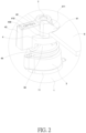
- FIG. 2 is a close-up view of Part A in FIG. 1 ;
- FIG. 3 is a stereogram of the present invention
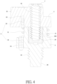
- FIG. 4 is a sectional view of the present invention.
- FIG. 5 is a three-dimensional exploded diagram of the present invention.
- FIG. 6 is a stereogram of the rotary latch in the present invention.
- FIG. 7 is a stereogram of the nut in the present invention.
- FIG. 8 is a stereogram of the nut in the present invention from another viewing angle
- FIG. 9 is a stereogram of the sealing cap in the present invention.
- FIG. 10 is an assembly drawing of circuit board and nut, connector and electronic device.
- FIGS. 1 - 9 show a circuit board connecting mechanism, including a circuit board 1 , a connector 2 , a fastener 3 , a rotary latch 4 and an elastic element 5 .
- the connector 2 is fixed to the circuit board 1 for inserting the electronic device 6 , and an electrical connection is formed, so as to transmit data steadily.
- the electronic device 6 is an M.2 Solid State Drive, which is a Solid State Drive with an M.2 interface, and universally used in circuit boards for its small size and high-speed transmission, for example, most computers use M.2 Solid State Drive at present.
- the fastener 3 is fixed to the circuit board 1 and can be removed from the circuit board 1 ; the rotary latch 4 is rotatably installed on the upper end of the fastener 3 , the elastic element 5 is disposed between the fastener 3 and the rotary latch 4 , forming steady assembly of the rotary latch 4 and fastener 3 , when the rotary latch 4 is rotated against the fastener 3 , the elastic element 5 is compressed, and after the rotary latch 4 is loosened, the rotary latch 4 can be reset through the elastic element 5 .
- a latch body 41 protruding outwards is disposed on the outer side of the upper end of the rotary latch 4 , the upper end of the latch body 41 is provided with a guiding slope 411 ; one end of the electronic device 6 is connected to the connector 2 , the other end of the electronic device 6 is pressed down to make the other end of the electronic device 6 press the guiding slope 411 of the latch body 41 , forcing the rotary latch 4 to rotate against the fastener 3 and compress the elastic element 5 , when the other end of the electronic device 6 is pressed over the latch body 41 , automatic reset of the rotary latch 4 is implemented by the torsion of the elastic element 5 , and the latch body 41 is pressed on the upper end face of the other end of the electronic device 6 , the other end of the electronic device 6 is locked, so that the electronic device 6 is fixed to the circuit board 1 , and stable electrical conduction is formed.
- the other end of the electronic device 6 after the other end of the electronic device 6 is pressed directly, the other end of the electronic device 6 can be locked on the circuit board 1 , which is convenient to operate, can be replaced quickly, and the assembly efficiency is improved. It does not need to remove screws with traditional tools such as screwdrivers, the operating time is shortened.
- the lower end of the latch body 41 is integrated with a reinforcing part 410 , the reinforcing part 410 and the rotary latch 4 are integrally fixed, so as to enhance the structural strength of the latch body 41 , the combination of the latch body 41 and the rotary latch 4 is steadier, preventing the latch body 41 from snapping against the rotary latch 4 , and a locking slot 40 for locking the other end of the electronic device 6 is formed between the lower end face of the latch body 41 and the side face of the reinforcing part 410 and the rotary latch 4 , so as to lock the other end of the electronic device 6 through the locking slot 40 .
- the assembly method of the rotary latch 4 and the fastener 3 is as follows: a through-hole 42 is drilled downwards in the upper end of the rotary latch 4 , and a screw hole 31 corresponding to the through-hole 42 is arranged in the upper end of the fastener 3 , a screw 7 is fixed in the screw hole 31 through the through-hole 42 , and the rotary latch 4 is rotated against the fastener 3 with the screw 7 as the rotating shaft, the screw 7 fixes the rotary latch 4 , the elastic element 5 and the fastener 3 together to form an integer, the integer is installed on the circuit board 1 in a detachable way, so as to implement overall assembly and disassembly, the application is more convenient.
- the upper part of the screw 7 is a slick rod, and the lower part is a thread, so that the slick rod of the screw 7 is placed in the through-hole 42 , and the rotary latch 4 can rotate with the rotary latch 4 as the axle body, the lower part of the screw 7 is screwed in the screw hole 31 , so that the screw 7 is fixed to the fastener 3 .
- the elastic element 5 provides the elastic force in the rotation direction between the rotary latch 4 and the fastener 3 , so that the rotary latch 4 and the fastener 3 are assembled steadily, and the rotary latch 4 , the elastic element 5 and the fastener 3 will not drop off during the vibration test.
- the lower end of the rotary latch 4 is provided with a travel restraining groove 44
- the upper end of the fastener 3 is provided with a slider 32
- the slider 32 is placed in the travel restraining groove 44
- the slider 32 only moves in the travel restraining groove 44 , so as to limit the rotation angle of the rotary latch 4 against the fastener 3 .
- a mounting hole 300 is disposed in the fastener 3 , a metal threaded sleeve 30 is fixed in the mounting hole 300 , the metal threaded sleeve 30 has the screw hole 31 , a first teeth 301 and a second teeth 302 distributed vertically are formed on the periphery of the upper end and the periphery of the lower end of the metal threaded sleeve 30 respectively, the first teeth 301 and the second teeth 302 are clamped and positioned with the inner wall of the mounting hole 300 , so that the metal threaded sleeve 30 is steadily installed in the mounting hole 300 of the fastener 3 , the spiral fixing of metal threaded sleeve 30 and screw 7 can guarantee steadier assembly structure and prevent strip.
- a handle 43 is disposed on the outer side of the upper end of the rotary latch 4 .
- the handle 43 is pushed directly with a finger to drive the rotary latch 4 to rotate, until the latch body 41 of the rotary latch 4 leaves the other end of the electronic device 6 .
- the other end of the electronic device 6 can be moved up to leave the rotary latch 4 , so as to unlock the electronic device 6 , the operation is very convenient.
- the handle 43 of the rotary latch 4 is released, the rotary latch 4 is reset automatically by the torsion of the elastic element 5 to prepare for next locking.
- the upper end of the handle 43 is integrally extended to the upper end of the rotary latch 4
- the lower end of the handle 43 is integrally extended to the lower end of the rotary latch 4 , so as to lengthen the handle 43 for the operator to rotate the rotary latch 4 conveniently.
- the upper end face of the handle 43 is provided with an operation mark 430 for convenient observation and operation; the operation mark 430 includes the rotation direction arrows and an OPEN slot.
- the guiding slope 411 is a twisted bevel face, which can better contact the other end of the electronic device 6 , and can better implement rotation, so as to buckle the other end of the electronic device 6 to lock the other end of the electronic device 6 .
- the elastic element 5 includes an elastic body 51 , an upper positioning part 52 formed at the upper end of the elastic body 51 and a lower positioning part 53 formed at the lower end of the elastic body 51 .
- the elastic body 51 is fitted over the upper end of the fastener 3 , the lower positioning part 53 penetrates into the lower limit hole 34 arranged in the fastener 3 , and the upper positioning part 52 penetrates into the upper limit hole 45 arranged in the rotary latch 4 , so that the elastic element 5 is firmly installed between the rotary latch 4 and the fastener 3 .
- the elastic element 5 can be a torsion spring or a spring piece, the elastic element 5 in this case is a torsion spring, which has the advantage of convenient assembly.
- a threaded stud 35 is formed at the lower end of the fastener 3 , the threaded stud 35 is fixed to the circuit board 1 , the assembly is more convenient.
- the following design is made: several nuts 11 distributed in a row are fixed to the circuit board 1 , t the fastener 3 is screwed to any nut 11 through the threaded stud 35 , so as to implement steady assembly without damaging the circuit board 1 . Moreover, several nuts 11 distributed in a row are fixed to the circuit board 1 , the distances between the nuts 11 and the connector 2 are different, so it can be used to lock the electronic device 6 of different sizes.
- the nuts 11 relatively far from the connector 2 can be used, when the threaded stud 35 of the fastener 3 is spirally installed on the nut 11 , the fastener 3 and the rotary latch 4 are fastened to the nut 11 , and the electronic device 6 is locked by the rotary latch 4 , so the present invention can lock electronic devices of different sizes, it is more applicable and more convenient.
- a slick rod 36 with a guiding function is formed at the lower end of the threaded stud 35 , the slick rod 36 penetrates into the nut 11 , until the external thread of the threaded stud 35 can rapidly contact the internal thread of the nut 11 , a threaded connection is formed, the slick rod 36 plays a guiding role in assembly, the operation is very convenient.
- a restraining groove 111 is arranged on the periphery of the nut 11 , the lower positioning part 53 of the elastic element 5 passes through the lower limit hole 34 of the fastener 3 to extend out of the lower end face of the fastener 3 , and can move up and down in the lower limit hole 34 , after the threaded stud 35 is screwed in position against the nut 11 , the lower positioning part 53 is embedded in the restraining groove 111 of the nut 11 .
- the lower positioning part 53 of the elastic element 5 extends out of the lower end face of the fastener 3 , in the screwing process of the threaded stud 35 against the nut 11 , the lower positioning part 53 is inserted in the restraining groove 111 of the nut 11 until the threaded stud 35 is screwed in position against the nut 11 , so as to guarantee the relative position of the latch body 41 on the outer side of the upper end of the rotary latch 4 , and the latch body 41 is always in the position where the pressed electronic device 6 can be stopped in normal state, the pressed electronic device 6 can be pressed on the guiding slope 411 of the latch body 41 .
- the nut 11 not used on the circuit board 1 can be enveloped in a sealing cap 12 to prevent foreign materials or dust from entering the nut 11 . Meanwhile, the sealing cap 12 can be easily sucked by the manipulator.
- the lower end of the sealing cap 12 is provided with a first arcuate latch 121 and a second arcuate latch 122 distributed symmetrically and positioning posts 123 by the first arcuate latch 121 and the second arcuate latch 122 , the first arcuate latch 121 and the second arcuate latch 122 are buckled into the nut 11 for tensioning and positioning, the positioning post 123 is inserted in the restraining groove 111 disposed on the periphery of the nut 11 , so as to make sure the sealing cap 12 can be stably loaded on the nut 11 , and to protect the internal thread of nut 11 and the external restraining groove 111 .
- the back side of the nut 11 is bent to form a pin 114 , when the nut 11 is placed in the mounting hole of the circuit board 1 , the pin 114 is inserted into the plug hole by the mounting hole on the circuit board 1 at the same time, so that the nut 11 is fixed to the circuit board 1 .
- one side wall of the restraining groove 111 is set as a inclined guiding surface 113 , so that when the rotary latch 4 , elastic element 5 and fastener 3 are integrally screwed out of the nut 11 , the lower positioning part 53 of the elastic element 5 will slide out along the inclined guiding surface 113 , the removal is more convenient.
- a layer of Mylar can be pasted on the unused nut 11 , which can achieve the above effect of assembling the sealing cap 12 .
- the present invention disposes an elastic element 5 between the rotary latch 4 and the fastener 3 , a latch body 41 protruding outwards is disposed on the outer side of the upper end of the rotary latch 4 , and a guiding slope 411 is disposed at the upper end of the latch body 41 ; in the course of operation, one end of the electronic device 6 is connected to the connector 2 , and the other end of the electronic device 6 is pressed down to make the other end of the electronic device 6 press the guiding slope 411 of the latch body 41 , forcing the rotary latch 4 to rotate against the fastener 3 and compress the elastic element 5 elastically, when the other end of the electronic device 6 is pressed over the latch body 41 , the rotary latch 4 is reset automatically by the torsion of the elastic element 5 , making the latch body 41 press the upper end face of the other end of the electronic device 6 , the other end of the electronic device 6 is locked, so that the electronic device 6 is fixed to the circuit board 1 , and stable electrical conduction is formed.
- the other end of the electronic device 6 When the other end of the electronic device 6 is pressed directly, the other end of the electronic device 6 can be locked on the circuit board 1 , the operation is very convenient, quick replacement is implemented, and the assembly efficiency is increased.
- the screws can be removed without conventional screwdrivers, the operating time is shortened a lot.
Landscapes
- Engineering & Computer Science (AREA)
- Microelectronics & Electronic Packaging (AREA)
- Details Of Connecting Devices For Male And Female Coupling (AREA)
Abstract
A circuit board connecting mechanism comprises a connector fixed to the circuit board, a fastener, a rotary latch, and an elastic element, when the rotary latch rotates against the fastener, it can be reset by the elastic element; one end of the electronic device is connected to the connector, the other end of the electronic device is pressed down to make the other end of the electronic device press the guiding slope of the buckle, forcing the rotary latch to rotate against the fastener and compress the elastic element, when the other end of the electronic device is pressed over the buckle, the rotary latch is reset by the torsion of the elastic element, making the buckle press the upper end face of the other end of the electronic device to lock the other end of the electronic device.
Description
- The present invention relates generally to the field of electronic technology, and more particularly to a circuit board connecting mechanism.
- To connect and assemble an electronic device (e.g., M.2 Solid State Drive) with a circuit board, one end of the electronic device shall be inserted in the connector disposed on the circuit board to form electrical conduction, and the other end of the electronic device is placed on the positioning post disposed on the circuit board, and fixed to the positioning post by screws through the holes in the circuit board, so as to fasten the other end of the electronic device to the circuit board. Finally, the entire electronic device is stably assembled on the circuit board, ensuring stable electrical conduction between the electronic device and the circuit board.
- The assembly method requires screw locking, the screws shall be removed for installation or removal, the operation is complicated, the assembly is slow, the efficiency is low, and the screws are small and likely to be lost in the assembly process, causing troubles to the operator.
- The purpose of the present invention is to overcome the deficiencies of the prior art and provide a circuit board connection mechanism.
- In order to solve the problems of the technologies described above, the present invention adopts the following technical solutions:
- A circuit board connecting mechanism comprising a connector fixed on a circuit board, a fastener, a rotary latch rotatably installed at an upper end of the fastener, and an elastic element disposed between the fastener and the rotary latch; the rotary latch can be repositioned by the elastic element after being rotated relative to the fastener; wherein the rotary latch has a protruding latch body on an upper outer side of the rotary latch, and a guiding slope provided at an upper end of the latch body; one end of an electronic device is connected to the connector, driving the other end of the electronic device to press against the guiding slope of the latch body and cause the rotary latch to rotate relative to the fastener and compress the elastic element, when the other end of the electronic device is pressed down past the latch body, the rotary latch returns to its original position through the torsional force of the elastic element, causing the latch body to engage with an upper end surface of said other end of the electronic device and lock the electronic device in place.
- More preferably, wherein the rotary latch is further provided with a handle on the upper outer side of the rotary latch, and the handle extends in one piece to an upper end of the rotary latch and extends in one piece to a lower end of the rotary latch, and an operation mark is also provided on an upper end surface of the handle; the guiding slope is a twisted slope.
- More preferably, wherein the rotary latch is provided with a through hole downwards along an upper end of the through hole, and the fixed member is provided with a corresponding screw hole with the through hole; a screw passes through the through hole and is screwed into the screw hole, and the rotary latch rotates relative to the fastener using the screw as a pivot, and the screw fixes the rotary latch, elastic element and fastener together to form an assembly that is detachably installed on the circuit board.
- More preferably, wherein the lower end of the rotary latch is provided with a travel limiting groove, and the upper end of the fastener is provided with a slider which is positioned within the travel limiting groove; the fastener is internally provided with a mounting hole, and a metal threaded sleeve is embedded and fixedly mounted within the mounting hole, the metal threaded sleeve having the aforementioned screw hole, and the upper and lower peripheries of the metal threaded sleeve are respectively formed with vertically distributed first teeth and second teeth, and both the first teeth and the second teeth are engaged with and positioned by an inner wall of the mounting hole.
- More preferably, wherein the elastic element is a torsion spring or a leaf spring; the lower end of the latch body is integrally connected with a reinforcing part, which is fixed integrally with the rotary latch, so that a locking groove is formed between a lower end face of the latch body and a side surface of the reinforcing part and the rotary fastener for locking another end of the electronic device.
- More preferably, wherein the elastic element includes an elastic body and an upper positioning part formed at an upper end of the elastic body and a lower positioning part formed at a lower end of the elastic body; the elastic body is sleeved on the upper end of the fastener, the lower positioning part passes through a lower limit hole provided on the fastener, and the upper positioning part passes through an upper limit hole provided on the rotary latch.
- More preferably, wherein the fastener is formed with a threaded stud at the lower end thereof; a plurality of nuts arranged in a row are fixed on the circuit board, and the fastener is spiral-fixed in any one of the nuts through the threaded stud to be fixed on the circuit board; a lower end of the threaded stud is also formed with a slick rod with guiding function, which penetrates into the nut through the slick rod.
- More preferably, wherein the periphery of the nut is provided with a restraining groove, and the lower positioning part of the elastic member passes through the lower limit hole of the fastener to extend out of the lower end surface of the fastener, and can move up and down in the lower limit hole, and after the threaded stud is spiraled into place relative to the nut, the lower positioning part is embedded in the restraining groove of the nut.
- More preferably, wherein one sidewall of the restraining groove is configured with an inclined guiding surface.
- More preferably, wherein a layer of Mylar can be applied on top of the nut when not in use, or alternatively, the nut can be covered by a sealing cap having a first arcuate latch and a second arcuate latch symmetrically disposed at a lower end thereof, and a positioning post located adjacent to the first arcuate latch and the second arcuate latch, wherein the first arcuate latch and the second arcuate latch are latched into the nut and tightened by positioning, and the positioning post is inserted into the restraining groove arranged around the periphery of the nut.
-
FIG. 1 is an operating state diagram of the present invention; -
FIG. 2 is a close-up view of Part A inFIG. 1 ; -
FIG. 3 is a stereogram of the present invention; -
FIG. 4 is a sectional view of the present invention; -
FIG. 5 is a three-dimensional exploded diagram of the present invention; -
FIG. 6 is a stereogram of the rotary latch in the present invention; -
FIG. 7 is a stereogram of the nut in the present invention; -
FIG. 8 is a stereogram of the nut in the present invention from another viewing angle; -
FIG. 9 is a stereogram of the sealing cap in the present invention; -
FIG. 10 is an assembly drawing of circuit board and nut, connector and electronic device. -
FIGS. 1-9 show a circuit board connecting mechanism, including acircuit board 1, aconnector 2, afastener 3, arotary latch 4 and anelastic element 5. - The
connector 2 is fixed to thecircuit board 1 for inserting theelectronic device 6, and an electrical connection is formed, so as to transmit data steadily. In this case, theelectronic device 6 is an M.2 Solid State Drive, which is a Solid State Drive with an M.2 interface, and universally used in circuit boards for its small size and high-speed transmission, for example, most computers use M.2 Solid State Drive at present. - The
fastener 3 is fixed to thecircuit board 1 and can be removed from thecircuit board 1; therotary latch 4 is rotatably installed on the upper end of thefastener 3, theelastic element 5 is disposed between thefastener 3 and therotary latch 4, forming steady assembly of therotary latch 4 and fastener 3, when therotary latch 4 is rotated against thefastener 3, theelastic element 5 is compressed, and after therotary latch 4 is loosened, therotary latch 4 can be reset through theelastic element 5. - A
latch body 41 protruding outwards is disposed on the outer side of the upper end of therotary latch 4, the upper end of thelatch body 41 is provided with a guidingslope 411; one end of theelectronic device 6 is connected to theconnector 2, the other end of theelectronic device 6 is pressed down to make the other end of theelectronic device 6 press the guidingslope 411 of thelatch body 41, forcing therotary latch 4 to rotate against thefastener 3 and compress theelastic element 5, when the other end of theelectronic device 6 is pressed over thelatch body 41, automatic reset of therotary latch 4 is implemented by the torsion of theelastic element 5, and thelatch body 41 is pressed on the upper end face of the other end of theelectronic device 6, the other end of theelectronic device 6 is locked, so that theelectronic device 6 is fixed to thecircuit board 1, and stable electrical conduction is formed. In this invention, after the other end of theelectronic device 6 is pressed directly, the other end of theelectronic device 6 can be locked on thecircuit board 1, which is convenient to operate, can be replaced quickly, and the assembly efficiency is improved. It does not need to remove screws with traditional tools such as screwdrivers, the operating time is shortened. - The lower end of the
latch body 41 is integrated with areinforcing part 410, thereinforcing part 410 and therotary latch 4 are integrally fixed, so as to enhance the structural strength of thelatch body 41, the combination of thelatch body 41 and therotary latch 4 is steadier, preventing thelatch body 41 from snapping against therotary latch 4, and alocking slot 40 for locking the other end of theelectronic device 6 is formed between the lower end face of thelatch body 41 and the side face of thereinforcing part 410 and therotary latch 4, so as to lock the other end of theelectronic device 6 through thelocking slot 40. - The assembly method of the
rotary latch 4 and thefastener 3 is as follows: a through-hole 42 is drilled downwards in the upper end of therotary latch 4, and ascrew hole 31 corresponding to the through-hole 42 is arranged in the upper end of thefastener 3, ascrew 7 is fixed in thescrew hole 31 through the through-hole 42, and therotary latch 4 is rotated against thefastener 3 with thescrew 7 as the rotating shaft, thescrew 7 fixes therotary latch 4, theelastic element 5 and thefastener 3 together to form an integer, the integer is installed on thecircuit board 1 in a detachable way, so as to implement overall assembly and disassembly, the application is more convenient. Additionally, the upper part of thescrew 7 is a slick rod, and the lower part is a thread, so that the slick rod of thescrew 7 is placed in the through-hole 42, and therotary latch 4 can rotate with therotary latch 4 as the axle body, the lower part of thescrew 7 is screwed in thescrew hole 31, so that thescrew 7 is fixed to thefastener 3. - The
elastic element 5 provides the elastic force in the rotation direction between therotary latch 4 and thefastener 3, so that therotary latch 4 and thefastener 3 are assembled steadily, and therotary latch 4, theelastic element 5 and thefastener 3 will not drop off during the vibration test. - In order to limit the rotation angle of the
rotary latch 4 against thefastener 3, the following design is made: the lower end of therotary latch 4 is provided with atravel restraining groove 44, the upper end of thefastener 3 is provided with aslider 32, theslider 32 is placed in thetravel restraining groove 44, and theslider 32 only moves in thetravel restraining groove 44, so as to limit the rotation angle of therotary latch 4 against thefastener 3. - A
mounting hole 300 is disposed in thefastener 3, a metal threadedsleeve 30 is fixed in themounting hole 300, the metal threadedsleeve 30 has thescrew hole 31, afirst teeth 301 and asecond teeth 302 distributed vertically are formed on the periphery of the upper end and the periphery of the lower end of the metal threadedsleeve 30 respectively, thefirst teeth 301 and thesecond teeth 302 are clamped and positioned with the inner wall of themounting hole 300, so that the metal threadedsleeve 30 is steadily installed in themounting hole 300 of thefastener 3, the spiral fixing of metal threadedsleeve 30 andscrew 7 can guarantee steadier assembly structure and prevent strip. - A
handle 43 is disposed on the outer side of the upper end of therotary latch 4. To unlock theelectronic device 6 which has been locked by thelatch body 41, thehandle 43 is pushed directly with a finger to drive therotary latch 4 to rotate, until thelatch body 41 of therotary latch 4 leaves the other end of theelectronic device 6. At this point, the other end of theelectronic device 6 can be moved up to leave therotary latch 4, so as to unlock theelectronic device 6, the operation is very convenient. After thehandle 43 of therotary latch 4 is released, therotary latch 4 is reset automatically by the torsion of theelastic element 5 to prepare for next locking. - The upper end of the
handle 43 is integrally extended to the upper end of therotary latch 4, the lower end of thehandle 43 is integrally extended to the lower end of therotary latch 4, so as to lengthen thehandle 43 for the operator to rotate therotary latch 4 conveniently. - The upper end face of the
handle 43 is provided with anoperation mark 430 for convenient observation and operation; theoperation mark 430 includes the rotation direction arrows and an OPEN slot. - The guiding
slope 411 is a twisted bevel face, which can better contact the other end of theelectronic device 6, and can better implement rotation, so as to buckle the other end of theelectronic device 6 to lock the other end of theelectronic device 6. - The
elastic element 5 includes anelastic body 51, anupper positioning part 52 formed at the upper end of theelastic body 51 and alower positioning part 53 formed at the lower end of theelastic body 51. Theelastic body 51 is fitted over the upper end of thefastener 3, thelower positioning part 53 penetrates into thelower limit hole 34 arranged in thefastener 3, and theupper positioning part 52 penetrates into theupper limit hole 45 arranged in therotary latch 4, so that theelastic element 5 is firmly installed between therotary latch 4 and thefastener 3. - The
elastic element 5 can be a torsion spring or a spring piece, theelastic element 5 in this case is a torsion spring, which has the advantage of convenient assembly. - A threaded
stud 35 is formed at the lower end of thefastener 3, the threadedstud 35 is fixed to thecircuit board 1, the assembly is more convenient. - As shown in
FIG. 10 , to avoid the threadedstud 35 of thefastener 3 damaging thecircuit board 1 in the assembly process, the following design is made:several nuts 11 distributed in a row are fixed to thecircuit board 1, t thefastener 3 is screwed to anynut 11 through the threadedstud 35, so as to implement steady assembly without damaging thecircuit board 1. Moreover,several nuts 11 distributed in a row are fixed to thecircuit board 1, the distances between thenuts 11 and theconnector 2 are different, so it can be used to lock theelectronic device 6 of different sizes. Specifically, for a longelectronic device 6, thenuts 11 relatively far from theconnector 2 can be used, when the threadedstud 35 of thefastener 3 is spirally installed on thenut 11, thefastener 3 and therotary latch 4 are fastened to thenut 11, and theelectronic device 6 is locked by therotary latch 4, so the present invention can lock electronic devices of different sizes, it is more applicable and more convenient. - A
slick rod 36 with a guiding function is formed at the lower end of the threadedstud 35, theslick rod 36 penetrates into thenut 11, until the external thread of the threadedstud 35 can rapidly contact the internal thread of thenut 11, a threaded connection is formed, theslick rod 36 plays a guiding role in assembly, the operation is very convenient. - In addition, a
restraining groove 111 is arranged on the periphery of thenut 11, thelower positioning part 53 of theelastic element 5 passes through thelower limit hole 34 of thefastener 3 to extend out of the lower end face of thefastener 3, and can move up and down in thelower limit hole 34, after the threadedstud 35 is screwed in position against thenut 11, thelower positioning part 53 is embedded in therestraining groove 111 of thenut 11. Furthermore, only a small part of thelower positioning part 53 of theelastic element 5 extends out of the lower end face of thefastener 3, in the screwing process of the threadedstud 35 against thenut 11, thelower positioning part 53 is inserted in therestraining groove 111 of thenut 11 until the threadedstud 35 is screwed in position against thenut 11, so as to guarantee the relative position of thelatch body 41 on the outer side of the upper end of therotary latch 4, and thelatch body 41 is always in the position where the pressedelectronic device 6 can be stopped in normal state, the pressedelectronic device 6 can be pressed on the guidingslope 411 of thelatch body 41. - The
nut 11 not used on thecircuit board 1 can be enveloped in a sealingcap 12 to prevent foreign materials or dust from entering thenut 11. Meanwhile, thesealing cap 12 can be easily sucked by the manipulator. - The lower end of the sealing
cap 12 is provided with a firstarcuate latch 121 and a secondarcuate latch 122 distributed symmetrically and positioningposts 123 by the firstarcuate latch 121 and the secondarcuate latch 122, the firstarcuate latch 121 and the secondarcuate latch 122 are buckled into thenut 11 for tensioning and positioning, thepositioning post 123 is inserted in therestraining groove 111 disposed on the periphery of thenut 11, so as to make sure the sealingcap 12 can be stably loaded on thenut 11, and to protect the internal thread ofnut 11 and theexternal restraining groove 111. - The back side of the
nut 11 is bent to form apin 114, when thenut 11 is placed in the mounting hole of thecircuit board 1, thepin 114 is inserted into the plug hole by the mounting hole on thecircuit board 1 at the same time, so that thenut 11 is fixed to thecircuit board 1. - In addition, one side wall of the restraining
groove 111 is set as a inclined guidingsurface 113, so that when therotary latch 4,elastic element 5 andfastener 3 are integrally screwed out of thenut 11, thelower positioning part 53 of theelastic element 5 will slide out along the inclined guidingsurface 113, the removal is more convenient. - Moreover, a layer of Mylar can be pasted on the
unused nut 11, which can achieve the above effect of assembling the sealingcap 12. - To sum up, the present invention disposes an
elastic element 5 between therotary latch 4 and thefastener 3, alatch body 41 protruding outwards is disposed on the outer side of the upper end of therotary latch 4, and a guidingslope 411 is disposed at the upper end of thelatch body 41; in the course of operation, one end of theelectronic device 6 is connected to theconnector 2, and the other end of theelectronic device 6 is pressed down to make the other end of theelectronic device 6 press the guidingslope 411 of thelatch body 41, forcing therotary latch 4 to rotate against thefastener 3 and compress theelastic element 5 elastically, when the other end of theelectronic device 6 is pressed over thelatch body 41, therotary latch 4 is reset automatically by the torsion of theelastic element 5, making thelatch body 41 press the upper end face of the other end of theelectronic device 6, the other end of theelectronic device 6 is locked, so that theelectronic device 6 is fixed to thecircuit board 1, and stable electrical conduction is formed. When the other end of theelectronic device 6 is pressed directly, the other end of theelectronic device 6 can be locked on thecircuit board 1, the operation is very convenient, quick replacement is implemented, and the assembly efficiency is increased. The screws can be removed without conventional screwdrivers, the operating time is shortened a lot.
Claims (10)
1. A circuit board connecting mechanism comprising
a connector (2) fixed on a circuit board (1), a fastener (3), a rotary latch (4) rotatably installed at an upper end of the fastener (3), and an elastic element (5) disposed between the fastener (3) and the rotary latch (4); the rotary latch (4) can be repositioned by the elastic element (5) after being rotated relative to the fastener (3);
wherein the rotary latch (4) has a protruding latch body (41) on an upper outer side of the rotary latch (4), and a guiding slope (411) provided at an upper end of the latch body (41); one end of an electronic device (6) is connected to the connector (2), driving the other end of the electronic device (6) to press against the guiding slope (411) of the latch body (41) and cause the rotary latch (4) to rotate relative to the fastener (3) and compress the elastic element (5),
when the other end of the electronic device (6) is pressed down past the latch body (41), the rotary latch (4) returns to its original position through the torsional force of the elastic element (5), causing the latch body (41) to engage with an upper end surface of said other end of the electronic device (6) and lock the electronic device in place.
2. The circuit board connecting mechanism according to claim 1 , wherein the rotary latch (4) is further provided with a handle (43) on the upper outer side of the rotary latch (4), and the handle (43) extends in one piece to an upper end of the rotary latch (4) and extends in one piece to a lower end of the rotary latch (4), and an operation mark (430) is also provided on an upper end surface of the handle (43); the guiding slope (411) is a twisted slope.
3. The circuit board connecting mechanism according to claim 1 , wherein the rotary latch (4) is provided with a through hole (42) downwards along an upper end of the through hole (42), and the fixed member (3) is provided with a corresponding screw hole (31) with the through hole (42); a screw (7) passes through the through hole (42) and is screwed into the screw hole (31), and the rotary latch (4) rotates relative to the fastener (3) using the screw (7) as a pivot, and the screw (7) fixes the rotary latch (4), elastic element (5) and fastener (3) together to form an assembly that is detachably installed on the circuit board (1).
4. The circuit board connecting mechanism according to claim 3 , wherein the lower end of the rotary latch (4) is provided with a travel limiting groove (44), and the upper end of the fastener (3) is provided with a slider (32) which is positioned within the travel limiting groove (44); the fastener (3) is internally provided with a mounting hole (300), and a metal threaded sleeve (30) is embedded and fixedly mounted within the mounting hole (300), the metal threaded sleeve (30) having the aforementioned screw hole (31), and the upper and lower peripheries of the metal threaded sleeve (30) are respectively formed with vertically distributed first teeth (301) and second teeth (302), and both the first teeth (301) and the second teeth (302) are engaged with and positioned by an inner wall of the mounting hole (300).
5. The circuit board connecting mechanism according to claim 1 , wherein the elastic element (5) is a torsion spring or a leaf spring; the lower end of the latch body (41) is integrally connected with a reinforcing part (410), which is fixed integrally with the rotary latch (4), so that a locking groove (40) is formed between a lower end face of the latch body (41) and a side surface of the reinforcing part (410) and the rotary fastener (4) for locking another end of the electronic device (6).
6. The circuit board connecting mechanism according to claim 5 , wherein the elastic element (5) includes an elastic body (51) and an upper positioning part (52) formed at an upper end of the elastic body (51) and a lower positioning part (53) formed at a lower end of the elastic body (51); the elastic body (51) is sleeved on the upper end of the fastener (3), the lower positioning part (53) passes through a lower limit hole (34) provided on the fastener (3), and the upper positioning part (52) passes through an upper limit hole (45) provided on the rotary latch (4).
7. The circuit board connecting mechanism according to claim 1 , wherein the fastener (3) is formed with a threaded stud (35) at the lower end thereof; a plurality of nuts (11) arranged in a row are fixed on the circuit board (1), and the fastener (3) is spiral-fixed in any one of the nuts (11) through the threaded stud (35) to be fixed on the circuit board (1); a lower end of the threaded stud (35) is also formed with a slick rod (36) with guiding function, which penetrates into the nut (11) through the slick rod (36).
8. The circuit board connecting mechanism according to claim 7 , wherein the periphery of the nut (11) is provided with a restraining groove (111), and the lower positioning part (53) of the elastic member (5) passes through the lower limit hole (34) of the fastener (3) to extend out of the lower end surface of the fastener (3), and can move up and down in the lower limit hole (34), and after the threaded stud (35) is spiraled into place relative to the nut (11), the lower positioning part (53) is embedded in the restraining groove (111) of the nut (11).
9. The circuit board connecting mechanism according to claim 7 , wherein one sidewall of the restraining groove (111) is configured with an inclined guiding surface (113).
10. The circuit board connecting mechanism according to claim 8 , wherein a layer of Mylar can be applied on top of the nut (11) when not in use, or alternatively, the nut (11) can be covered by a sealing cap (12) having a first arcuate latch (121) and a second arcuate latch (122) symmetrically disposed at a lower end thereof, and a positioning post (123) located adjacent to the first arcuate latch (121) and the second arcuate latch (122), wherein the first arcuate latch (121) and the second arcuate latch (122) are latched into the nut (11) and tightened by positioning, and the positioning post (123) is inserted into the restraining groove (111) arranged around the periphery of the nut (11).
Priority Applications (1)
| Application Number | Priority Date | Filing Date | Title |
|---|---|---|---|
| US18/176,495 US20240297459A1 (en) | 2023-03-01 | 2023-03-01 | Circuit board connecting mechanism |
Applications Claiming Priority (1)
| Application Number | Priority Date | Filing Date | Title |
|---|---|---|---|
| US18/176,495 US20240297459A1 (en) | 2023-03-01 | 2023-03-01 | Circuit board connecting mechanism |
Publications (1)
| Publication Number | Publication Date |
|---|---|
| US20240297459A1 true US20240297459A1 (en) | 2024-09-05 |
Family
ID=92544488
Family Applications (1)
| Application Number | Title | Priority Date | Filing Date |
|---|---|---|---|
| US18/176,495 Pending US20240297459A1 (en) | 2023-03-01 | 2023-03-01 | Circuit board connecting mechanism |
Country Status (1)
| Country | Link |
|---|---|
| US (1) | US20240297459A1 (en) |
Cited By (2)
| Publication number | Priority date | Publication date | Assignee | Title |
|---|---|---|---|---|
| US20240268052A1 (en) * | 2023-02-07 | 2024-08-08 | Dell Products L.P. | Sliding latch for retention of peripheral device |
| US20250031309A1 (en) * | 2023-07-19 | 2025-01-23 | Adlink Technology Inc. | Mounting assembly and circuit board assembly |
-
2023
- 2023-03-01 US US18/176,495 patent/US20240297459A1/en active Pending
Cited By (4)
| Publication number | Priority date | Publication date | Assignee | Title |
|---|---|---|---|---|
| US20240268052A1 (en) * | 2023-02-07 | 2024-08-08 | Dell Products L.P. | Sliding latch for retention of peripheral device |
| US12324119B2 (en) * | 2023-02-07 | 2025-06-03 | Dell Products L.P. | Sliding latch for retention of peripheral device |
| US20250031309A1 (en) * | 2023-07-19 | 2025-01-23 | Adlink Technology Inc. | Mounting assembly and circuit board assembly |
| US12363829B2 (en) * | 2023-07-19 | 2025-07-15 | Adlink Technology Inc. | Mounting assembly and circuit board assembly |
Similar Documents
| Publication | Publication Date | Title |
|---|---|---|
| US20240297459A1 (en) | Circuit board connecting mechanism | |
| US20090181568A1 (en) | Locking handle | |
| US7708580B2 (en) | Electrical connector with a load plate fastened to a printed circuit board by screws | |
| CN215910919U (en) | Interface device fixing mechanism and electronic device | |
| TWM536292U (en) | Fastening device | |
| CN219248184U (en) | Circuit board connecting mechanism | |
| US6544065B1 (en) | ZIF socket connector | |
| US5232375A (en) | Parallel latching device for connectors | |
| CN115599174A (en) | Electronic module and electronic device | |
| CN114126218B (en) | Circuit board connection mechanism | |
| US20030228785A1 (en) | Electrical connector having driving cam | |
| TWM630596U (en) | Circuit board connecting mechanism | |
| CN219248185U (en) | Circuit board fixing seat structure | |
| US7359187B2 (en) | Apparatus for mounting removably a disk drive in an electronic device | |
| CN103894814A (en) | Riveting device | |
| JP2959568B1 (en) | Board insertion / extraction device | |
| CN219843794U (en) | Fastening devices and electronic equipment | |
| US6206715B1 (en) | Actuating tool for use with ZIF sockets | |
| JP4441290B2 (en) | Chassis and unit connection structure | |
| CN121440287A (en) | Press rotary circuit board connecting mechanism | |
| CN218975672U (en) | Anti-falling structure of threaded fastener of electronic scale | |
| US12328834B1 (en) | Electronic devices with anti-disassembly mechanisms and the operation method thereof | |
| CN221957397U (en) | Chassis top cover lock and chassis | |
| CN217956194U (en) | Rotary screw structure and socket using same | |
| CN219917646U (en) | Fastening devices and electronic equipment |
Legal Events
| Date | Code | Title | Description |
|---|---|---|---|
| STPP | Information on status: patent application and granting procedure in general |
Free format text: DOCKETED NEW CASE - READY FOR EXAMINATION |
|
| STCB | Information on status: application discontinuation |
Free format text: ABANDONED -- FAILURE TO RESPOND TO AN OFFICE ACTION |
|
| STPP | Information on status: patent application and granting procedure in general |
Free format text: NON FINAL ACTION MAILED |
|
| STCB | Information on status: application discontinuation |
Free format text: ABANDONED -- FAILURE TO RESPOND TO AN OFFICE ACTION |