US20240297308A1 - Binder, liquid composition, storage container, electrode production device, electrode production method, electrode, electrochemical element, device, and moving body - Google Patents
Binder, liquid composition, storage container, electrode production device, electrode production method, electrode, electrochemical element, device, and moving body Download PDFInfo
- Publication number
- US20240297308A1 US20240297308A1 US18/593,182 US202418593182A US2024297308A1 US 20240297308 A1 US20240297308 A1 US 20240297308A1 US 202418593182 A US202418593182 A US 202418593182A US 2024297308 A1 US2024297308 A1 US 2024297308A1
- Authority
- US
- United States
- Prior art keywords
- liquid composition
- electrode
- binder
- solid electrolyte
- group
- Prior art date
- Legal status (The legal status is an assumption and is not a legal conclusion. Google has not performed a legal analysis and makes no representation as to the accuracy of the status listed.)
- Pending
Links
- 239000007788 liquid Substances 0.000 title claims abstract description 232
- 239000000203 mixture Substances 0.000 title claims abstract description 230
- 239000011230 binding agent Substances 0.000 title claims abstract description 158
- 238000004519 manufacturing process Methods 0.000 title claims description 66
- 238000003860 storage Methods 0.000 title claims description 26
- 239000007784 solid electrolyte Substances 0.000 claims abstract description 120
- 239000007774 positive electrode material Substances 0.000 claims abstract description 26
- 239000002131 composite material Substances 0.000 claims description 89
- 125000000217 alkyl group Chemical group 0.000 claims description 47
- 125000004432 carbon atom Chemical group C* 0.000 claims description 34
- 239000002904 solvent Substances 0.000 claims description 32
- 125000002947 alkylene group Chemical group 0.000 claims description 29
- 229910052744 lithium Inorganic materials 0.000 claims description 23
- WHXSMMKQMYFTQS-UHFFFAOYSA-N Lithium Chemical compound [Li] WHXSMMKQMYFTQS-UHFFFAOYSA-N 0.000 claims description 21
- 239000002203 sulfidic glass Substances 0.000 claims description 20
- 125000004435 hydrogen atom Chemical group [H]* 0.000 claims description 16
- 125000001495 ethyl group Chemical group [H]C([H])([H])C([H])([H])* 0.000 claims description 11
- 125000002496 methyl group Chemical group [H]C([H])([H])* 0.000 claims description 11
- OKTJSMMVPCPJKN-UHFFFAOYSA-N Carbon Chemical compound [C] OKTJSMMVPCPJKN-UHFFFAOYSA-N 0.000 claims description 10
- 230000009477 glass transition Effects 0.000 claims description 10
- 125000001302 tertiary amino group Chemical group 0.000 claims description 10
- 229910052799 carbon Inorganic materials 0.000 claims description 9
- 125000004430 oxygen atom Chemical group O* 0.000 claims description 6
- 229910000314 transition metal oxide Inorganic materials 0.000 claims description 4
- 229910000319 transition metal phosphate Inorganic materials 0.000 claims description 3
- 125000002467 phosphate group Chemical class [H]OP(=O)(O[H])O[*] 0.000 claims 1
- 239000000126 substance Substances 0.000 abstract 1
- 239000010410 layer Substances 0.000 description 157
- 239000002585 base Substances 0.000 description 73
- 238000000034 method Methods 0.000 description 67
- YXFVVABEGXRONW-UHFFFAOYSA-N Toluene Chemical compound CC1=CC=CC=C1 YXFVVABEGXRONW-UHFFFAOYSA-N 0.000 description 45
- SOGAXMICEFXMKE-UHFFFAOYSA-N Butylmethacrylate Chemical compound CCCCOC(=O)C(C)=C SOGAXMICEFXMKE-UHFFFAOYSA-N 0.000 description 42
- 238000007599 discharging Methods 0.000 description 42
- 238000010438 heat treatment Methods 0.000 description 39
- 239000002270 dispersing agent Substances 0.000 description 38
- 238000012546 transfer Methods 0.000 description 36
- 239000011149 active material Substances 0.000 description 35
- 239000000463 material Substances 0.000 description 33
- SJIXRGNQPBQWMK-UHFFFAOYSA-N 2-(diethylamino)ethyl 2-methylprop-2-enoate Chemical compound CCN(CC)CCOC(=O)C(C)=C SJIXRGNQPBQWMK-UHFFFAOYSA-N 0.000 description 30
- 230000000052 comparative effect Effects 0.000 description 28
- 239000002245 particle Substances 0.000 description 26
- -1 ethylhexyl group Chemical group 0.000 description 23
- 230000015572 biosynthetic process Effects 0.000 description 20
- 239000000470 constituent Substances 0.000 description 20
- 238000010586 diagram Methods 0.000 description 20
- 238000007639 printing Methods 0.000 description 19
- 238000003786 synthesis reaction Methods 0.000 description 19
- 238000005452 bending Methods 0.000 description 18
- 238000011156 evaluation Methods 0.000 description 16
- 238000007334 copolymerization reaction Methods 0.000 description 15
- 239000010408 film Substances 0.000 description 15
- HBBGRARXTFLTSG-UHFFFAOYSA-N Lithium ion Chemical compound [Li+] HBBGRARXTFLTSG-UHFFFAOYSA-N 0.000 description 14
- 238000005520 cutting process Methods 0.000 description 14
- 229910001416 lithium ion Inorganic materials 0.000 description 14
- 238000000425 proton nuclear magnetic resonance spectrum Methods 0.000 description 14
- WYGWHHGCAGTUCH-UHFFFAOYSA-N 2-[(2-cyano-4-methylpentan-2-yl)diazenyl]-2,4-dimethylpentanenitrile Chemical compound CC(C)CC(C)(C#N)N=NC(C)(C#N)CC(C)C WYGWHHGCAGTUCH-UHFFFAOYSA-N 0.000 description 13
- 238000005336 cracking Methods 0.000 description 13
- 125000000484 butyl group Chemical group [H]C([*])([H])C([H])([H])C([H])([H])C([H])([H])[H] 0.000 description 12
- 150000001875 compounds Chemical class 0.000 description 12
- 230000007246 mechanism Effects 0.000 description 12
- 229910052782 aluminium Inorganic materials 0.000 description 11
- 230000000694 effects Effects 0.000 description 11
- PXHVJJICTQNCMI-UHFFFAOYSA-N Nickel Chemical compound [Ni] PXHVJJICTQNCMI-UHFFFAOYSA-N 0.000 description 10
- 239000008151 electrolyte solution Substances 0.000 description 10
- VVQNEPGJFQJSBK-UHFFFAOYSA-N Methyl methacrylate Chemical compound COC(=O)C(C)=C VVQNEPGJFQJSBK-UHFFFAOYSA-N 0.000 description 9
- 238000001035 drying Methods 0.000 description 9
- 230000001771 impaired effect Effects 0.000 description 9
- 239000007787 solid Substances 0.000 description 9
- JKNCOURZONDCGV-UHFFFAOYSA-N 2-(dimethylamino)ethyl 2-methylprop-2-enoate Chemical compound CN(C)CCOC(=O)C(C)=C JKNCOURZONDCGV-UHFFFAOYSA-N 0.000 description 8
- 238000005259 measurement Methods 0.000 description 8
- 229910052751 metal Inorganic materials 0.000 description 8
- 239000002184 metal Substances 0.000 description 8
- 125000001424 substituent group Chemical group 0.000 description 8
- WIYVVIUBKNTNKG-UHFFFAOYSA-N 6,7-dimethoxy-3,4-dihydronaphthalene-2-carboxylic acid Chemical compound C1CC(C(O)=O)=CC2=C1C=C(OC)C(OC)=C2 WIYVVIUBKNTNKG-UHFFFAOYSA-N 0.000 description 7
- 239000003792 electrolyte Substances 0.000 description 7
- IJGRMHOSHXDMSA-UHFFFAOYSA-N nitrogen Substances N#N IJGRMHOSHXDMSA-UHFFFAOYSA-N 0.000 description 7
- 239000003960 organic solvent Substances 0.000 description 7
- 229910052717 sulfur Inorganic materials 0.000 description 7
- 229910009176 Li2S—P2 Inorganic materials 0.000 description 6
- SECXISVLQFMRJM-UHFFFAOYSA-N N-Methylpyrrolidone Chemical compound CN1CCCC1=O SECXISVLQFMRJM-UHFFFAOYSA-N 0.000 description 6
- XAGFODPZIPBFFR-UHFFFAOYSA-N aluminium Chemical compound [Al] XAGFODPZIPBFFR-UHFFFAOYSA-N 0.000 description 6
- 239000003575 carbonaceous material Substances 0.000 description 6
- 238000000576 coating method Methods 0.000 description 6
- 239000013078 crystal Substances 0.000 description 6
- 125000002993 cycloalkylene group Chemical group 0.000 description 6
- 238000009826 distribution Methods 0.000 description 6
- 150000002148 esters Chemical class 0.000 description 6
- WABPQHHGFIMREM-UHFFFAOYSA-N lead(0) Chemical compound [Pb] WABPQHHGFIMREM-UHFFFAOYSA-N 0.000 description 6
- 238000000691 measurement method Methods 0.000 description 6
- VLKZOEOYAKHREP-UHFFFAOYSA-N n-Hexane Chemical compound CCCCCC VLKZOEOYAKHREP-UHFFFAOYSA-N 0.000 description 6
- 239000007773 negative electrode material Substances 0.000 description 6
- 229910052719 titanium Inorganic materials 0.000 description 6
- 239000010936 titanium Substances 0.000 description 6
- 230000032258 transport Effects 0.000 description 6
- XEEYBQQBJWHFJM-UHFFFAOYSA-N Iron Chemical compound [Fe] XEEYBQQBJWHFJM-UHFFFAOYSA-N 0.000 description 5
- 229910052733 gallium Inorganic materials 0.000 description 5
- 229910052732 germanium Inorganic materials 0.000 description 5
- 239000000178 monomer Substances 0.000 description 5
- 229910052759 nickel Inorganic materials 0.000 description 5
- 229910052757 nitrogen Inorganic materials 0.000 description 5
- 229920000642 polymer Polymers 0.000 description 5
- 239000002994 raw material Substances 0.000 description 5
- 229910052710 silicon Inorganic materials 0.000 description 5
- 239000003115 supporting electrolyte Substances 0.000 description 5
- 229910008323 Li-P-S Inorganic materials 0.000 description 4
- 229910006736 Li—P—S Inorganic materials 0.000 description 4
- WYURNTSHIVDZCO-UHFFFAOYSA-N Tetrahydrofuran Chemical compound C1CCOC1 WYURNTSHIVDZCO-UHFFFAOYSA-N 0.000 description 4
- 239000002253 acid Substances 0.000 description 4
- RDOXTESZEPMUJZ-UHFFFAOYSA-N anisole Chemical compound COC1=CC=CC=C1 RDOXTESZEPMUJZ-UHFFFAOYSA-N 0.000 description 4
- 229910052802 copper Inorganic materials 0.000 description 4
- 239000010949 copper Substances 0.000 description 4
- 150000002170 ethers Chemical class 0.000 description 4
- 230000006870 function Effects 0.000 description 4
- 239000011245 gel electrolyte Substances 0.000 description 4
- 125000005843 halogen group Chemical group 0.000 description 4
- KWGKDLIKAYFUFQ-UHFFFAOYSA-M lithium chloride Chemical compound [Li+].[Cl-] KWGKDLIKAYFUFQ-UHFFFAOYSA-M 0.000 description 4
- 229910003002 lithium salt Inorganic materials 0.000 description 4
- 159000000002 lithium salts Chemical class 0.000 description 4
- GLNWILHOFOBOFD-UHFFFAOYSA-N lithium sulfide Chemical compound [Li+].[Li+].[S-2] GLNWILHOFOBOFD-UHFFFAOYSA-N 0.000 description 4
- 238000002156 mixing Methods 0.000 description 4
- 125000001997 phenyl group Chemical group [H]C1=C([H])C([H])=C(*)C([H])=C1[H] 0.000 description 4
- 229910052698 phosphorus Inorganic materials 0.000 description 4
- 229920000768 polyamine Polymers 0.000 description 4
- 238000006116 polymerization reaction Methods 0.000 description 4
- 229910052718 tin Inorganic materials 0.000 description 4
- 239000011135 tin Substances 0.000 description 4
- 238000001291 vacuum drying Methods 0.000 description 4
- XLYOFNOQVPJJNP-UHFFFAOYSA-N water Substances O XLYOFNOQVPJJNP-UHFFFAOYSA-N 0.000 description 4
- ZWEHNKRNPOVVGH-UHFFFAOYSA-N 2-Butanone Chemical compound CCC(C)=O ZWEHNKRNPOVVGH-UHFFFAOYSA-N 0.000 description 3
- CSCPPACGZOOCGX-UHFFFAOYSA-N Acetone Chemical compound CC(C)=O CSCPPACGZOOCGX-UHFFFAOYSA-N 0.000 description 3
- OIFBSDVPJOWBCH-UHFFFAOYSA-N Diethyl carbonate Chemical compound CCOC(=O)OCC OIFBSDVPJOWBCH-UHFFFAOYSA-N 0.000 description 3
- RTZKZFJDLAIYFH-UHFFFAOYSA-N Diethyl ether Chemical compound CCOCC RTZKZFJDLAIYFH-UHFFFAOYSA-N 0.000 description 3
- XEKOWRVHYACXOJ-UHFFFAOYSA-N Ethyl acetate Chemical compound CCOC(C)=O XEKOWRVHYACXOJ-UHFFFAOYSA-N 0.000 description 3
- KMTRUDSVKNLOMY-UHFFFAOYSA-N Ethylene carbonate Chemical compound O=C1OCCO1 KMTRUDSVKNLOMY-UHFFFAOYSA-N 0.000 description 3
- 229910001290 LiPF6 Inorganic materials 0.000 description 3
- OKKJLVBELUTLKV-UHFFFAOYSA-N Methanol Chemical compound OC OKKJLVBELUTLKV-UHFFFAOYSA-N 0.000 description 3
- ZMXDDKWLCZADIW-UHFFFAOYSA-N N,N-Dimethylformamide Chemical compound CN(C)C=O ZMXDDKWLCZADIW-UHFFFAOYSA-N 0.000 description 3
- NINIDFKCEFEMDL-UHFFFAOYSA-N Sulfur Chemical compound [S] NINIDFKCEFEMDL-UHFFFAOYSA-N 0.000 description 3
- RTAQQCXQSZGOHL-UHFFFAOYSA-N Titanium Chemical compound [Ti] RTAQQCXQSZGOHL-UHFFFAOYSA-N 0.000 description 3
- 239000012790 adhesive layer Substances 0.000 description 3
- 229910052783 alkali metal Inorganic materials 0.000 description 3
- 150000001340 alkali metals Chemical class 0.000 description 3
- 150000004945 aromatic hydrocarbons Chemical class 0.000 description 3
- 150000004649 carbonic acid derivatives Chemical class 0.000 description 3
- 238000004140 cleaning Methods 0.000 description 3
- 125000002704 decyl group Chemical group [H]C([H])([H])C([H])([H])C([H])([H])C([H])([H])C([H])([H])C([H])([H])C([H])([H])C([H])([H])C([H])([H])C([H])([H])* 0.000 description 3
- 239000011521 glass Substances 0.000 description 3
- 239000002241 glass-ceramic Substances 0.000 description 3
- 229910000037 hydrogen sulfide Inorganic materials 0.000 description 3
- 125000002887 hydroxy group Chemical group [H]O* 0.000 description 3
- 229910052742 iron Inorganic materials 0.000 description 3
- 229910001386 lithium phosphate Inorganic materials 0.000 description 3
- 230000004048 modification Effects 0.000 description 3
- 238000012986 modification Methods 0.000 description 3
- QJGQUHMNIGDVPM-UHFFFAOYSA-N nitrogen group Chemical group [N] QJGQUHMNIGDVPM-UHFFFAOYSA-N 0.000 description 3
- 239000004745 nonwoven fabric Substances 0.000 description 3
- 229910052760 oxygen Inorganic materials 0.000 description 3
- 239000000123 paper Substances 0.000 description 3
- BASFCYQUMIYNBI-UHFFFAOYSA-N platinum Substances [Pt] BASFCYQUMIYNBI-UHFFFAOYSA-N 0.000 description 3
- 238000012545 processing Methods 0.000 description 3
- 125000004805 propylene group Chemical group [H]C([H])([H])C([H])([*:1])C([H])([H])[*:2] 0.000 description 3
- 238000007650 screen-printing Methods 0.000 description 3
- 239000000243 solution Substances 0.000 description 3
- 239000010935 stainless steel Substances 0.000 description 3
- 229910001220 stainless steel Inorganic materials 0.000 description 3
- 229910052715 tantalum Inorganic materials 0.000 description 3
- 238000012360 testing method Methods 0.000 description 3
- 150000003623 transition metal compounds Chemical class 0.000 description 3
- TWQULNDIKKJZPH-UHFFFAOYSA-K trilithium;phosphate Chemical compound [Li+].[Li+].[Li+].[O-]P([O-])([O-])=O TWQULNDIKKJZPH-UHFFFAOYSA-K 0.000 description 3
- 229910052720 vanadium Inorganic materials 0.000 description 3
- ZZXUZKXVROWEIF-UHFFFAOYSA-N 1,2-butylene carbonate Chemical compound CCC1COC(=O)O1 ZZXUZKXVROWEIF-UHFFFAOYSA-N 0.000 description 2
- YEJRWHAVMIAJKC-UHFFFAOYSA-N 4-Butyrolactone Chemical compound O=C1CCCO1 YEJRWHAVMIAJKC-UHFFFAOYSA-N 0.000 description 2
- 229910001558 CF3SO3Li Inorganic materials 0.000 description 2
- 229920000298 Cellophane Polymers 0.000 description 2
- RYGMFSIKBFXOCR-UHFFFAOYSA-N Copper Chemical compound [Cu] RYGMFSIKBFXOCR-UHFFFAOYSA-N 0.000 description 2
- RWSOTUBLDIXVET-UHFFFAOYSA-N Dihydrogen sulfide Chemical compound S RWSOTUBLDIXVET-UHFFFAOYSA-N 0.000 description 2
- XTHFKEDIFFGKHM-UHFFFAOYSA-N Dimethoxyethane Chemical compound COCCOC XTHFKEDIFFGKHM-UHFFFAOYSA-N 0.000 description 2
- IAZDPXIOMUYVGZ-UHFFFAOYSA-N Dimethylsulphoxide Chemical compound CS(C)=O IAZDPXIOMUYVGZ-UHFFFAOYSA-N 0.000 description 2
- 239000002227 LISICON Substances 0.000 description 2
- 229910010848 Li6PS5Cl Inorganic materials 0.000 description 2
- 229910002984 Li7La3Zr2O12 Inorganic materials 0.000 description 2
- CERQOIWHTDAKMF-UHFFFAOYSA-N Methacrylic acid Chemical compound CC(=C)C(O)=O CERQOIWHTDAKMF-UHFFFAOYSA-N 0.000 description 2
- 229910004600 P2S5 Inorganic materials 0.000 description 2
- 229920003171 Poly (ethylene oxide) Polymers 0.000 description 2
- 239000004698 Polyethylene Substances 0.000 description 2
- 239000002202 Polyethylene glycol Substances 0.000 description 2
- 239000004721 Polyphenylene oxide Substances 0.000 description 2
- 229920000388 Polyphosphate Polymers 0.000 description 2
- 229910020343 SiS2 Inorganic materials 0.000 description 2
- VYPSYNLAJGMNEJ-UHFFFAOYSA-N Silicium dioxide Chemical compound O=[Si]=O VYPSYNLAJGMNEJ-UHFFFAOYSA-N 0.000 description 2
- YWJVFBOUPMWANA-UHFFFAOYSA-H [Li+].[V+5].[O-]P([O-])([O-])=O.[O-]P([O-])([O-])=O Chemical compound [Li+].[V+5].[O-]P([O-])([O-])=O.[O-]P([O-])([O-])=O YWJVFBOUPMWANA-UHFFFAOYSA-H 0.000 description 2
- 238000010521 absorption reaction Methods 0.000 description 2
- 229910001413 alkali metal ion Inorganic materials 0.000 description 2
- 125000003545 alkoxy group Chemical group 0.000 description 2
- 229910045601 alloy Inorganic materials 0.000 description 2
- 239000000956 alloy Substances 0.000 description 2
- 125000003277 amino group Chemical group 0.000 description 2
- 238000005280 amorphization Methods 0.000 description 2
- QVGXLLKOCUKJST-UHFFFAOYSA-N atomic oxygen Chemical compound [O] QVGXLLKOCUKJST-UHFFFAOYSA-N 0.000 description 2
- 238000007611 bar coating method Methods 0.000 description 2
- 230000008901 benefit Effects 0.000 description 2
- 229910052796 boron Inorganic materials 0.000 description 2
- 229910052791 calcium Inorganic materials 0.000 description 2
- 150000001721 carbon Chemical group 0.000 description 2
- 125000003178 carboxy group Chemical group [H]OC(*)=O 0.000 description 2
- 230000008859 change Effects 0.000 description 2
- 238000006243 chemical reaction Methods 0.000 description 2
- 229910052804 chromium Inorganic materials 0.000 description 2
- 239000011651 chromium Substances 0.000 description 2
- 239000011248 coating agent Substances 0.000 description 2
- 125000004093 cyano group Chemical group *C#N 0.000 description 2
- 125000000753 cycloalkyl group Chemical group 0.000 description 2
- JHIVVAPYMSGYDF-UHFFFAOYSA-N cyclohexanone Chemical compound O=C1CCCCC1 JHIVVAPYMSGYDF-UHFFFAOYSA-N 0.000 description 2
- 230000007423 decrease Effects 0.000 description 2
- 230000007547 defect Effects 0.000 description 2
- 239000006185 dispersion Substances 0.000 description 2
- 238000010494 dissociation reaction Methods 0.000 description 2
- 230000005593 dissociations Effects 0.000 description 2
- 125000003438 dodecyl group Chemical group [H]C([H])([H])C([H])([H])C([H])([H])C([H])([H])C([H])([H])C([H])([H])C([H])([H])C([H])([H])C([H])([H])C([H])([H])C([H])([H])C([H])([H])* 0.000 description 2
- JBTWLSYIZRCDFO-UHFFFAOYSA-N ethyl methyl carbonate Chemical compound CCOC(=O)OC JBTWLSYIZRCDFO-UHFFFAOYSA-N 0.000 description 2
- 125000000816 ethylene group Chemical group [H]C([H])([*:1])C([H])([H])[*:2] 0.000 description 2
- 239000011888 foil Substances 0.000 description 2
- NVVZQXQBYZPMLJ-UHFFFAOYSA-N formaldehyde;naphthalene-1-sulfonic acid Chemical compound O=C.C1=CC=C2C(S(=O)(=O)O)=CC=CC2=C1 NVVZQXQBYZPMLJ-UHFFFAOYSA-N 0.000 description 2
- 238000005227 gel permeation chromatography Methods 0.000 description 2
- 229910052737 gold Inorganic materials 0.000 description 2
- 239000010931 gold Substances 0.000 description 2
- 229910002804 graphite Inorganic materials 0.000 description 2
- 239000010439 graphite Substances 0.000 description 2
- 238000007756 gravure coating Methods 0.000 description 2
- 125000003187 heptyl group Chemical group [H]C([*])([H])C([H])([H])C([H])([H])C([H])([H])C([H])([H])C([H])([H])C([H])([H])[H] 0.000 description 2
- 125000004051 hexyl group Chemical group [H]C([H])([H])C([H])([H])C([H])([H])C([H])([H])C([H])([H])C([H])([H])* 0.000 description 2
- 230000006872 improvement Effects 0.000 description 2
- 229910052738 indium Inorganic materials 0.000 description 2
- 238000007641 inkjet printing Methods 0.000 description 2
- 229910003480 inorganic solid Inorganic materials 0.000 description 2
- 125000000959 isobutyl group Chemical group [H]C([H])([H])C([H])(C([H])([H])[H])C([H])([H])* 0.000 description 2
- 125000001449 isopropyl group Chemical group [H]C([H])([H])C([H])(*)C([H])([H])[H] 0.000 description 2
- AMXOYNBUYSYVKV-UHFFFAOYSA-M lithium bromide Chemical compound [Li+].[Br-] AMXOYNBUYSYVKV-UHFFFAOYSA-M 0.000 description 2
- XGZVUEUWXADBQD-UHFFFAOYSA-L lithium carbonate Chemical compound [Li+].[Li+].[O-]C([O-])=O XGZVUEUWXADBQD-UHFFFAOYSA-L 0.000 description 2
- 229910052808 lithium carbonate Inorganic materials 0.000 description 2
- GELKBWJHTRAYNV-UHFFFAOYSA-K lithium iron phosphate Chemical compound [Li+].[Fe+2].[O-]P([O-])([O-])=O GELKBWJHTRAYNV-UHFFFAOYSA-K 0.000 description 2
- MHCFAGZWMAWTNR-UHFFFAOYSA-M lithium perchlorate Chemical compound [Li+].[O-]Cl(=O)(=O)=O MHCFAGZWMAWTNR-UHFFFAOYSA-M 0.000 description 2
- 229910001486 lithium perchlorate Inorganic materials 0.000 description 2
- 239000011572 manganese Substances 0.000 description 2
- UZKWTJUDCOPSNM-UHFFFAOYSA-N methoxybenzene Substances CCCCOC=C UZKWTJUDCOPSNM-UHFFFAOYSA-N 0.000 description 2
- TZIHFWKZFHZASV-UHFFFAOYSA-N methyl formate Chemical compound COC=O TZIHFWKZFHZASV-UHFFFAOYSA-N 0.000 description 2
- NUKZAGXMHTUAFE-UHFFFAOYSA-N methyl hexanoate Chemical compound CCCCCC(=O)OC NUKZAGXMHTUAFE-UHFFFAOYSA-N 0.000 description 2
- 229910052750 molybdenum Inorganic materials 0.000 description 2
- 125000002950 monocyclic group Chemical group 0.000 description 2
- 229910052758 niobium Inorganic materials 0.000 description 2
- 239000011255 nonaqueous electrolyte Substances 0.000 description 2
- 125000002347 octyl group Chemical group [H]C([*])([H])C([H])([H])C([H])([H])C([H])([H])C([H])([H])C([H])([H])C([H])([H])C([H])([H])[H] 0.000 description 2
- 239000001301 oxygen Substances 0.000 description 2
- 239000008188 pellet Substances 0.000 description 2
- 125000001147 pentyl group Chemical group C(CCCC)* 0.000 description 2
- 230000000737 periodic effect Effects 0.000 description 2
- 230000002093 peripheral effect Effects 0.000 description 2
- 150000003013 phosphoric acid derivatives Chemical class 0.000 description 2
- 239000000049 pigment Substances 0.000 description 2
- 229910052697 platinum Inorganic materials 0.000 description 2
- 229920001281 polyalkylene Polymers 0.000 description 2
- 229920000570 polyether Polymers 0.000 description 2
- 229920000573 polyethylene Polymers 0.000 description 2
- 229920001223 polyethylene glycol Polymers 0.000 description 2
- 230000000379 polymerizing effect Effects 0.000 description 2
- 239000001205 polyphosphate Substances 0.000 description 2
- 235000011176 polyphosphates Nutrition 0.000 description 2
- 229920001451 polypropylene glycol Polymers 0.000 description 2
- 238000002360 preparation method Methods 0.000 description 2
- 125000001436 propyl group Chemical group [H]C([*])([H])C([H])([H])C([H])([H])[H] 0.000 description 2
- RUOJZAUFBMNUDX-UHFFFAOYSA-N propylene carbonate Chemical compound CC1COC(=O)O1 RUOJZAUFBMNUDX-UHFFFAOYSA-N 0.000 description 2
- 238000004080 punching Methods 0.000 description 2
- 238000000746 purification Methods 0.000 description 2
- 125000001453 quaternary ammonium group Chemical group 0.000 description 2
- 230000009467 reduction Effects 0.000 description 2
- 238000001226 reprecipitation Methods 0.000 description 2
- 230000002441 reversible effect Effects 0.000 description 2
- 239000002002 slurry Substances 0.000 description 2
- 125000004079 stearyl group Chemical group [H]C([*])([H])C([H])([H])C([H])([H])C([H])([H])C([H])([H])C([H])([H])C([H])([H])C([H])([H])C([H])([H])C([H])([H])C([H])([H])C([H])([H])C([H])([H])C([H])([H])C([H])([H])C([H])([H])C([H])([H])C([H])([H])[H] 0.000 description 2
- 150000005846 sugar alcohols Polymers 0.000 description 2
- 239000011593 sulfur Substances 0.000 description 2
- GUVRBAGPIYLISA-UHFFFAOYSA-N tantalum atom Chemical compound [Ta] GUVRBAGPIYLISA-UHFFFAOYSA-N 0.000 description 2
- YLQBMQCUIZJEEH-UHFFFAOYSA-N tetrahydrofuran Natural products C=1C=COC=1 YLQBMQCUIZJEEH-UHFFFAOYSA-N 0.000 description 2
- 229910052721 tungsten Inorganic materials 0.000 description 2
- VAYTZRYEBVHVLE-UHFFFAOYSA-N 1,3-dioxol-2-one Chemical compound O=C1OC=CO1 VAYTZRYEBVHVLE-UHFFFAOYSA-N 0.000 description 1
- RYHBNJHYFVUHQT-UHFFFAOYSA-N 1,4-Dioxane Chemical compound C1COCCO1 RYHBNJHYFVUHQT-UHFFFAOYSA-N 0.000 description 1
- VXNZUUAINFGPBY-UHFFFAOYSA-N 1-Butene Chemical group CCC=C VXNZUUAINFGPBY-UHFFFAOYSA-N 0.000 description 1
- QLIBJPGWWSHWBF-UHFFFAOYSA-N 2-aminoethyl methacrylate Chemical compound CC(=C)C(=O)OCCN QLIBJPGWWSHWBF-UHFFFAOYSA-N 0.000 description 1
- 125000004828 2-ethylpropylene group Chemical group [H]C([H])([H])C([H])([H])C([H])(C([H])([H])[*:1])C([H])([H])[*:2] 0.000 description 1
- YXYJVFYWCLAXHO-UHFFFAOYSA-N 2-methoxyethyl 2-methylprop-2-enoate Chemical compound COCCOC(=O)C(C)=C YXYJVFYWCLAXHO-UHFFFAOYSA-N 0.000 description 1
- 125000004200 2-methoxyethyl group Chemical group [H]C([H])([H])OC([H])([H])C([H])([H])* 0.000 description 1
- AGJBKFAPBKOEGA-UHFFFAOYSA-M 2-methoxyethylmercury(1+);acetate Chemical compound COCC[Hg]OC(C)=O AGJBKFAPBKOEGA-UHFFFAOYSA-M 0.000 description 1
- BKOOMYPCSUNDGP-UHFFFAOYSA-N 2-methylbut-2-ene Chemical group CC=C(C)C BKOOMYPCSUNDGP-UHFFFAOYSA-N 0.000 description 1
- DKPFZGUDAPQIHT-UHFFFAOYSA-N Butyl acetate Natural products CCCCOC(C)=O DKPFZGUDAPQIHT-UHFFFAOYSA-N 0.000 description 1
- VYZAMTAEIAYCRO-UHFFFAOYSA-N Chromium Chemical compound [Cr] VYZAMTAEIAYCRO-UHFFFAOYSA-N 0.000 description 1
- 229910020680 Co—Ni—Mn Inorganic materials 0.000 description 1
- 229910016861 F9SO3 Inorganic materials 0.000 description 1
- 229910005842 GeS2 Inorganic materials 0.000 description 1
- 101100190537 Homo sapiens PNN gene Proteins 0.000 description 1
- 229910019271 La0.55Li0.35TiO3 Inorganic materials 0.000 description 1
- 229910006570 Li1+xMn2-xO4 Inorganic materials 0.000 description 1
- 229910006628 Li1+xMn2−xO4 Inorganic materials 0.000 description 1
- 229910008745 Li2O-B2O3-P2O5 Inorganic materials 0.000 description 1
- 229910008590 Li2O—B2O3—P2O5 Inorganic materials 0.000 description 1
- 229910008656 Li2O—SiO2 Inorganic materials 0.000 description 1
- 229910009099 Li2S-Al2S3 Inorganic materials 0.000 description 1
- 229910009292 Li2S-GeS2 Inorganic materials 0.000 description 1
- 229910009293 Li2S-GeS2-Ga2S3 Inorganic materials 0.000 description 1
- 229910009290 Li2S-GeS2-P2S5 Inorganic materials 0.000 description 1
- 229910009297 Li2S-P2S5 Inorganic materials 0.000 description 1
- 229910009303 Li2S-P2S5-LiCl Inorganic materials 0.000 description 1
- 229910009311 Li2S-SiS2 Inorganic materials 0.000 description 1
- 229910009324 Li2S-SiS2-Li3PO4 Inorganic materials 0.000 description 1
- 229910009326 Li2S-SiS2-Li4SiO4 Inorganic materials 0.000 description 1
- 229910009318 Li2S-SiS2-LiI Inorganic materials 0.000 description 1
- 229910009328 Li2S-SiS2—Li3PO4 Inorganic materials 0.000 description 1
- 229910007307 Li2S:P2S5 Inorganic materials 0.000 description 1
- 229910009329 Li2S—Al2S3 Inorganic materials 0.000 description 1
- 229910009338 Li2S—Ga2S3 Inorganic materials 0.000 description 1
- 229910009351 Li2S—GeS2 Inorganic materials 0.000 description 1
- 229910009353 Li2S—GeS2—Al2S3 Inorganic materials 0.000 description 1
- 229910009108 Li2S—GeS2—Ga2S3 Inorganic materials 0.000 description 1
- 229910009110 Li2S—GeS2—P2S5 Inorganic materials 0.000 description 1
- 229910009102 Li2S—GeS2—Sb2S5 Inorganic materials 0.000 description 1
- 229910009130 Li2S—GeS2—ZnS Inorganic materials 0.000 description 1
- 229910009148 Li2S—Li2O—P2S5 Inorganic materials 0.000 description 1
- 229910009142 Li2S—Li3PO4—P2S5 Inorganic materials 0.000 description 1
- 229910009145 Li2S—LiI—Li2O—P2S5 Inorganic materials 0.000 description 1
- 229910009181 Li2S—LiI—P2S5 Inorganic materials 0.000 description 1
- 229910009228 Li2S—P2S5 Inorganic materials 0.000 description 1
- 229910009237 Li2S—P2S5—LiCl Inorganic materials 0.000 description 1
- 229910009433 Li2S—SiS2 Inorganic materials 0.000 description 1
- 229910007282 Li2S—SiS2—Al2S3 Inorganic materials 0.000 description 1
- 229910007295 Li2S—SiS2—Li3PO4 Inorganic materials 0.000 description 1
- 229910007290 Li2S—SiS2—Li4SiO4 Inorganic materials 0.000 description 1
- 229910007289 Li2S—SiS2—LiI Inorganic materials 0.000 description 1
- 229910007306 Li2S—SiS2—P2S5LiI Inorganic materials 0.000 description 1
- 229910012323 Li3.5Zn0.25GeO4 Inorganic materials 0.000 description 1
- 229910012329 Li3BO3—Li2SO4 Inorganic materials 0.000 description 1
- 229910012605 Li3PO(4-3/2w)Nw Inorganic materials 0.000 description 1
- 229910012606 Li3PO(4−3/2w)Nw Inorganic materials 0.000 description 1
- 229910010640 Li6BaLa2Ta2O12 Inorganic materials 0.000 description 1
- 229910052493 LiFePO4 Inorganic materials 0.000 description 1
- 229910002099 LiNi0.5Mn1.5O4 Inorganic materials 0.000 description 1
- 229910003005 LiNiO2 Inorganic materials 0.000 description 1
- 229910012305 LiPON Inorganic materials 0.000 description 1
- 229910012666 LiTi2P3O12 Inorganic materials 0.000 description 1
- 229910018058 Ni-Co-Al Inorganic materials 0.000 description 1
- 229910018102 Ni-Mn-Al Inorganic materials 0.000 description 1
- 229910018144 Ni—Co—Al Inorganic materials 0.000 description 1
- 229910018548 Ni—Mn—Al Inorganic materials 0.000 description 1
- CTQNGGLPUBDAKN-UHFFFAOYSA-N O-Xylene Chemical compound CC1=CC=CC=C1C CTQNGGLPUBDAKN-UHFFFAOYSA-N 0.000 description 1
- OAICVXFJPJFONN-UHFFFAOYSA-N Phosphorus Chemical compound [P] OAICVXFJPJFONN-UHFFFAOYSA-N 0.000 description 1
- 102100038374 Pinin Human genes 0.000 description 1
- 239000004952 Polyamide Substances 0.000 description 1
- 239000004743 Polypropylene Substances 0.000 description 1
- 239000004793 Polystyrene Substances 0.000 description 1
- 241000156302 Porcine hemagglutinating encephalomyelitis virus Species 0.000 description 1
- VKCLPVFDVVKEKU-UHFFFAOYSA-N S=[P] Chemical compound S=[P] VKCLPVFDVVKEKU-UHFFFAOYSA-N 0.000 description 1
- 229910000676 Si alloy Inorganic materials 0.000 description 1
- 229910052581 Si3N4 Inorganic materials 0.000 description 1
- XUIMIQQOPSSXEZ-UHFFFAOYSA-N Silicon Chemical compound [Si] XUIMIQQOPSSXEZ-UHFFFAOYSA-N 0.000 description 1
- 229910001128 Sn alloy Inorganic materials 0.000 description 1
- KEAYESYHFKHZAL-UHFFFAOYSA-N Sodium Chemical compound [Na] KEAYESYHFKHZAL-UHFFFAOYSA-N 0.000 description 1
- UCKMPCXJQFINFW-UHFFFAOYSA-N Sulphide Chemical compound [S-2] UCKMPCXJQFINFW-UHFFFAOYSA-N 0.000 description 1
- 229910010252 TiO3 Inorganic materials 0.000 description 1
- ATJFFYVFTNAWJD-UHFFFAOYSA-N Tin Chemical compound [Sn] ATJFFYVFTNAWJD-UHFFFAOYSA-N 0.000 description 1
- GWEVSGVZZGPLCZ-UHFFFAOYSA-N Titan oxide Chemical compound O=[Ti]=O GWEVSGVZZGPLCZ-UHFFFAOYSA-N 0.000 description 1
- 229920002978 Vinylon Polymers 0.000 description 1
- 239000006230 acetylene black Substances 0.000 description 1
- 239000000654 additive Substances 0.000 description 1
- 230000002411 adverse Effects 0.000 description 1
- 238000004220 aggregation Methods 0.000 description 1
- 230000002776 aggregation Effects 0.000 description 1
- HSFWRNGVRCDJHI-UHFFFAOYSA-N alpha-acetylene Natural products C#C HSFWRNGVRCDJHI-UHFFFAOYSA-N 0.000 description 1
- 150000001408 amides Chemical class 0.000 description 1
- 150000001450 anions Chemical class 0.000 description 1
- 229910052787 antimony Inorganic materials 0.000 description 1
- 239000000010 aprotic solvent Substances 0.000 description 1
- 239000007864 aqueous solution Substances 0.000 description 1
- 239000003125 aqueous solvent Substances 0.000 description 1
- 229910052785 arsenic Inorganic materials 0.000 description 1
- 229910021383 artificial graphite Inorganic materials 0.000 description 1
- 125000003118 aryl group Chemical group 0.000 description 1
- 125000004429 atom Chemical group 0.000 description 1
- 239000011324 bead Substances 0.000 description 1
- 238000009835 boiling Methods 0.000 description 1
- 229910052794 bromium Inorganic materials 0.000 description 1
- IAQRGUVFOMOMEM-UHFFFAOYSA-N but-2-ene Chemical group CC=CC IAQRGUVFOMOMEM-UHFFFAOYSA-N 0.000 description 1
- 239000002134 carbon nanofiber Substances 0.000 description 1
- 229910021393 carbon nanotube Inorganic materials 0.000 description 1
- 239000002041 carbon nanotube Substances 0.000 description 1
- 238000005266 casting Methods 0.000 description 1
- 239000012295 chemical reaction liquid Substances 0.000 description 1
- 229910052801 chlorine Inorganic materials 0.000 description 1
- 229910017052 cobalt Inorganic materials 0.000 description 1
- 239000010941 cobalt Substances 0.000 description 1
- GUTLYIVDDKVIGB-UHFFFAOYSA-N cobalt atom Chemical compound [Co] GUTLYIVDDKVIGB-UHFFFAOYSA-N 0.000 description 1
- 229910000428 cobalt oxide Inorganic materials 0.000 description 1
- IVMYJDGYRUAWML-UHFFFAOYSA-N cobalt(ii) oxide Chemical compound [Co]=O IVMYJDGYRUAWML-UHFFFAOYSA-N 0.000 description 1
- 239000004020 conductor Substances 0.000 description 1
- 238000001816 cooling Methods 0.000 description 1
- 230000001351 cycling effect Effects 0.000 description 1
- 125000004979 cyclopentylene group Chemical group 0.000 description 1
- 238000010908 decantation Methods 0.000 description 1
- 238000000354 decomposition reaction Methods 0.000 description 1
- GTBGXKPAKVYEKJ-UHFFFAOYSA-N decyl 2-methylprop-2-enoate Chemical compound CCCCCCCCCCOC(=O)C(C)=C GTBGXKPAKVYEKJ-UHFFFAOYSA-N 0.000 description 1
- 230000006866 deterioration Effects 0.000 description 1
- 125000001664 diethylamino group Chemical group [H]C([H])([H])C([H])([H])N(*)C([H])([H])C([H])([H])[H] 0.000 description 1
- 238000009792 diffusion process Methods 0.000 description 1
- QHGJSLXSVXVKHZ-UHFFFAOYSA-N dilithium;dioxido(dioxo)manganese Chemical compound [Li+].[Li+].[O-][Mn]([O-])(=O)=O QHGJSLXSVXVKHZ-UHFFFAOYSA-N 0.000 description 1
- IEJIGPNLZYLLBP-UHFFFAOYSA-N dimethyl carbonate Chemical compound COC(=O)OC IEJIGPNLZYLLBP-UHFFFAOYSA-N 0.000 description 1
- 125000002147 dimethylamino group Chemical group [H]C([H])([H])N(*)C([H])([H])[H] 0.000 description 1
- 238000003618 dip coating Methods 0.000 description 1
- 125000004914 dipropylamino group Chemical group C(CC)N(CCC)* 0.000 description 1
- 239000002612 dispersion medium Substances 0.000 description 1
- 239000000428 dust Substances 0.000 description 1
- 238000010894 electron beam technology Methods 0.000 description 1
- 125000005677 ethinylene group Chemical group [*:2]C#C[*:1] 0.000 description 1
- SUPCQIBBMFXVTL-UHFFFAOYSA-N ethyl 2-methylprop-2-enoate Chemical compound CCOC(=O)C(C)=C SUPCQIBBMFXVTL-UHFFFAOYSA-N 0.000 description 1
- 230000001747 exhibiting effect Effects 0.000 description 1
- 239000004744 fabric Substances 0.000 description 1
- 239000000835 fiber Substances 0.000 description 1
- 229910052731 fluorine Inorganic materials 0.000 description 1
- 239000002223 garnet Substances 0.000 description 1
- 239000007789 gas Substances 0.000 description 1
- 238000002309 gasification Methods 0.000 description 1
- 239000003365 glass fiber Substances 0.000 description 1
- PCHJSUWPFVWCPO-UHFFFAOYSA-N gold Chemical compound [Au] PCHJSUWPFVWCPO-UHFFFAOYSA-N 0.000 description 1
- 229910021389 graphene Inorganic materials 0.000 description 1
- 229910021469 graphitizable carbon Inorganic materials 0.000 description 1
- 238000007646 gravure printing Methods 0.000 description 1
- 229910021385 hard carbon Inorganic materials 0.000 description 1
- FUZZWVXGSFPDMH-UHFFFAOYSA-N hexanoic acid Chemical compound CCCCCC(O)=O FUZZWVXGSFPDMH-UHFFFAOYSA-N 0.000 description 1
- 229910052740 iodine Inorganic materials 0.000 description 1
- 150000002500 ions Chemical class 0.000 description 1
- 150000002576 ketones Chemical class 0.000 description 1
- 239000002655 kraft paper Substances 0.000 description 1
- 150000003903 lactic acid esters Chemical class 0.000 description 1
- 239000004973 liquid crystal related substance Substances 0.000 description 1
- 229910001547 lithium hexafluoroantimonate(V) Inorganic materials 0.000 description 1
- 229910001540 lithium hexafluoroarsenate(V) Inorganic materials 0.000 description 1
- HSZCZNFXUDYRKD-UHFFFAOYSA-M lithium iodide Inorganic materials [Li+].[I-] HSZCZNFXUDYRKD-UHFFFAOYSA-M 0.000 description 1
- 229910001537 lithium tetrachloroaluminate Inorganic materials 0.000 description 1
- 229910001496 lithium tetrafluoroborate Inorganic materials 0.000 description 1
- ILXAVRFGLBYNEJ-UHFFFAOYSA-K lithium;manganese(2+);phosphate Chemical compound [Li+].[Mn+2].[O-]P([O-])([O-])=O ILXAVRFGLBYNEJ-UHFFFAOYSA-K 0.000 description 1
- 230000003137 locomotive effect Effects 0.000 description 1
- 229910052749 magnesium Inorganic materials 0.000 description 1
- 229910052748 manganese Inorganic materials 0.000 description 1
- WPBNNNQJVZRUHP-UHFFFAOYSA-L manganese(2+);methyl n-[[2-(methoxycarbonylcarbamothioylamino)phenyl]carbamothioyl]carbamate;n-[2-(sulfidocarbothioylamino)ethyl]carbamodithioate Chemical compound [Mn+2].[S-]C(=S)NCCNC([S-])=S.COC(=O)NC(=S)NC1=CC=CC=C1NC(=S)NC(=O)OC WPBNNNQJVZRUHP-UHFFFAOYSA-L 0.000 description 1
- 238000003701 mechanical milling Methods 0.000 description 1
- QZIQJVCYUQZDIR-UHFFFAOYSA-N mechlorethamine hydrochloride Chemical compound Cl.ClCCN(C)CCCl QZIQJVCYUQZDIR-UHFFFAOYSA-N 0.000 description 1
- 239000004750 melt-blown nonwoven Substances 0.000 description 1
- 238000007578 melt-quenching technique Methods 0.000 description 1
- 239000002923 metal particle Substances 0.000 description 1
- VNWKTOKETHGBQD-UHFFFAOYSA-N methane Chemical class C VNWKTOKETHGBQD-UHFFFAOYSA-N 0.000 description 1
- 125000001570 methylene group Chemical group [H]C([H])([*:1])[*:2] 0.000 description 1
- 239000011259 mixed solution Substances 0.000 description 1
- 239000002808 molecular sieve Substances 0.000 description 1
- 125000004573 morpholin-4-yl group Chemical group N1(CCOCC1)* 0.000 description 1
- 229910021382 natural graphite Inorganic materials 0.000 description 1
- 229910000480 nickel oxide Inorganic materials 0.000 description 1
- 229910021470 non-graphitizable carbon Inorganic materials 0.000 description 1
- 238000007645 offset printing Methods 0.000 description 1
- GNRSAWUEBMWBQH-UHFFFAOYSA-N oxonickel Chemical compound [Ni]=O GNRSAWUEBMWBQH-UHFFFAOYSA-N 0.000 description 1
- 125000004817 pentamethylene group Chemical group [H]C([H])([*:2])C([H])([H])C([H])([H])C([H])([H])C([H])([H])[*:1] 0.000 description 1
- 239000011574 phosphorus Substances 0.000 description 1
- 150000003018 phosphorus compounds Chemical class 0.000 description 1
- CYQAYERJWZKYML-UHFFFAOYSA-N phosphorus pentasulfide Chemical compound S1P(S2)(=S)SP3(=S)SP1(=S)SP2(=S)S3 CYQAYERJWZKYML-UHFFFAOYSA-N 0.000 description 1
- 239000003495 polar organic solvent Substances 0.000 description 1
- 239000002798 polar solvent Substances 0.000 description 1
- 229920001490 poly(butyl methacrylate) polymer Polymers 0.000 description 1
- 229920003229 poly(methyl methacrylate) Polymers 0.000 description 1
- 229920002647 polyamide Polymers 0.000 description 1
- 239000004926 polymethyl methacrylate Substances 0.000 description 1
- 229920000098 polyolefin Polymers 0.000 description 1
- 229920001155 polypropylene Polymers 0.000 description 1
- 229920002223 polystyrene Polymers 0.000 description 1
- 229910052700 potassium Inorganic materials 0.000 description 1
- 239000002244 precipitate Substances 0.000 description 1
- 230000008569 process Effects 0.000 description 1
- 239000000047 product Substances 0.000 description 1
- 239000003586 protic polar solvent Substances 0.000 description 1
- 229920005604 random copolymer Polymers 0.000 description 1
- 229910052707 ruthenium Inorganic materials 0.000 description 1
- 239000004576 sand Substances 0.000 description 1
- 238000007789 sealing Methods 0.000 description 1
- 239000013049 sediment Substances 0.000 description 1
- 239000010703 silicon Substances 0.000 description 1
- HQVNEWCFYHHQES-UHFFFAOYSA-N silicon nitride Chemical compound N12[Si]34N5[Si]62N3[Si]51N64 HQVNEWCFYHHQES-UHFFFAOYSA-N 0.000 description 1
- 229910052814 silicon oxide Inorganic materials 0.000 description 1
- 229910052708 sodium Inorganic materials 0.000 description 1
- 239000011734 sodium Substances 0.000 description 1
- URGAHOPLAPQHLN-UHFFFAOYSA-N sodium aluminosilicate Chemical compound [Na+].[Al+3].[O-][Si]([O-])=O.[O-][Si]([O-])=O URGAHOPLAPQHLN-UHFFFAOYSA-N 0.000 description 1
- 229910052979 sodium sulfide Inorganic materials 0.000 description 1
- GRVFOGOEDUUMBP-UHFFFAOYSA-N sodium sulfide (anhydrous) Chemical compound [Na+].[Na+].[S-2] GRVFOGOEDUUMBP-UHFFFAOYSA-N 0.000 description 1
- 229910021384 soft carbon Inorganic materials 0.000 description 1
- 239000011343 solid material Substances 0.000 description 1
- 239000006104 solid solution Substances 0.000 description 1
- 238000001179 sorption measurement Methods 0.000 description 1
- 238000001228 spectrum Methods 0.000 description 1
- 238000004528 spin coating Methods 0.000 description 1
- 229910052596 spinel Inorganic materials 0.000 description 1
- 239000011029 spinel Substances 0.000 description 1
- 238000005507 spraying Methods 0.000 description 1
- 238000003756 stirring Methods 0.000 description 1
- 229910052712 strontium Inorganic materials 0.000 description 1
- 239000000758 substrate Substances 0.000 description 1
- 150000004763 sulfides Chemical class 0.000 description 1
- HXJUTPCZVOIRIF-UHFFFAOYSA-N sulfolane Chemical compound O=S1(=O)CCCC1 HXJUTPCZVOIRIF-UHFFFAOYSA-N 0.000 description 1
- 125000004434 sulfur atom Chemical group 0.000 description 1
- 239000002226 superionic conductor Substances 0.000 description 1
- 239000006228 supernatant Substances 0.000 description 1
- 238000001308 synthesis method Methods 0.000 description 1
- 230000002194 synthesizing effect Effects 0.000 description 1
- 125000000383 tetramethylene group Chemical group [H]C([H])([*:1])C([H])([H])C([H])([H])C([H])([H])[*:2] 0.000 description 1
- 239000010409 thin film Substances 0.000 description 1
- XOLBLPGZBRYERU-UHFFFAOYSA-N tin dioxide Chemical compound O=[Sn]=O XOLBLPGZBRYERU-UHFFFAOYSA-N 0.000 description 1
- 229910001887 tin oxide Inorganic materials 0.000 description 1
- OGIDPMRJRNCKJF-UHFFFAOYSA-N titanium oxide Inorganic materials [Ti]=O OGIDPMRJRNCKJF-UHFFFAOYSA-N 0.000 description 1
- 238000009966 trimming Methods 0.000 description 1
- 238000001132 ultrasonic dispersion Methods 0.000 description 1
- GPPXJZIENCGNKB-UHFFFAOYSA-N vanadium Chemical compound [V]#[V] GPPXJZIENCGNKB-UHFFFAOYSA-N 0.000 description 1
- 238000004804 winding Methods 0.000 description 1
- 239000008096 xylene Substances 0.000 description 1
- 229910052727 yttrium Inorganic materials 0.000 description 1
- 229910052725 zinc Inorganic materials 0.000 description 1
- 229910052726 zirconium Inorganic materials 0.000 description 1
Images


Classifications
-
- H—ELECTRICITY
- H01—ELECTRIC ELEMENTS
- H01M—PROCESSES OR MEANS, e.g. BATTERIES, FOR THE DIRECT CONVERSION OF CHEMICAL ENERGY INTO ELECTRICAL ENERGY
- H01M4/00—Electrodes
- H01M4/02—Electrodes composed of, or comprising, active material
- H01M4/04—Processes of manufacture in general
- H01M4/0402—Methods of deposition of the material
- H01M4/0407—Methods of deposition of the material by coating on an electrolyte layer
-
- H—ELECTRICITY
- H01—ELECTRIC ELEMENTS
- H01M—PROCESSES OR MEANS, e.g. BATTERIES, FOR THE DIRECT CONVERSION OF CHEMICAL ENERGY INTO ELECTRICAL ENERGY
- H01M10/00—Secondary cells; Manufacture thereof
- H01M10/05—Accumulators with non-aqueous electrolyte
- H01M10/052—Li-accumulators
-
- H—ELECTRICITY
- H01—ELECTRIC ELEMENTS
- H01M—PROCESSES OR MEANS, e.g. BATTERIES, FOR THE DIRECT CONVERSION OF CHEMICAL ENERGY INTO ELECTRICAL ENERGY
- H01M10/00—Secondary cells; Manufacture thereof
- H01M10/05—Accumulators with non-aqueous electrolyte
- H01M10/056—Accumulators with non-aqueous electrolyte characterised by the materials used as electrolytes, e.g. mixed inorganic/organic electrolytes
- H01M10/0561—Accumulators with non-aqueous electrolyte characterised by the materials used as electrolytes, e.g. mixed inorganic/organic electrolytes the electrolyte being constituted of inorganic materials only
- H01M10/0562—Solid materials
-
- H—ELECTRICITY
- H01—ELECTRIC ELEMENTS
- H01M—PROCESSES OR MEANS, e.g. BATTERIES, FOR THE DIRECT CONVERSION OF CHEMICAL ENERGY INTO ELECTRICAL ENERGY
- H01M10/00—Secondary cells; Manufacture thereof
- H01M10/05—Accumulators with non-aqueous electrolyte
- H01M10/058—Construction or manufacture
- H01M10/0585—Construction or manufacture of accumulators having only flat construction elements, i.e. flat positive electrodes, flat negative electrodes and flat separators
-
- H—ELECTRICITY
- H01—ELECTRIC ELEMENTS
- H01M—PROCESSES OR MEANS, e.g. BATTERIES, FOR THE DIRECT CONVERSION OF CHEMICAL ENERGY INTO ELECTRICAL ENERGY
- H01M4/00—Electrodes
- H01M4/02—Electrodes composed of, or comprising, active material
- H01M4/04—Processes of manufacture in general
- H01M4/0402—Methods of deposition of the material
- H01M4/0404—Methods of deposition of the material by coating on electrode collectors
-
- H—ELECTRICITY
- H01—ELECTRIC ELEMENTS
- H01M—PROCESSES OR MEANS, e.g. BATTERIES, FOR THE DIRECT CONVERSION OF CHEMICAL ENERGY INTO ELECTRICAL ENERGY
- H01M4/00—Electrodes
- H01M4/02—Electrodes composed of, or comprising, active material
- H01M4/13—Electrodes for accumulators with non-aqueous electrolyte, e.g. for lithium-accumulators; Processes of manufacture thereof
- H01M4/139—Processes of manufacture
- H01M4/1391—Processes of manufacture of electrodes based on mixed oxides or hydroxides, or on mixtures of oxides or hydroxides, e.g. LiCoOx
-
- H—ELECTRICITY
- H01—ELECTRIC ELEMENTS
- H01M—PROCESSES OR MEANS, e.g. BATTERIES, FOR THE DIRECT CONVERSION OF CHEMICAL ENERGY INTO ELECTRICAL ENERGY
- H01M4/00—Electrodes
- H01M4/02—Electrodes composed of, or comprising, active material
- H01M4/13—Electrodes for accumulators with non-aqueous electrolyte, e.g. for lithium-accumulators; Processes of manufacture thereof
- H01M4/139—Processes of manufacture
- H01M4/1397—Processes of manufacture of electrodes based on inorganic compounds other than oxides or hydroxides, e.g. sulfides, selenides, tellurides, halogenides or LiCoFy
-
- H—ELECTRICITY
- H01—ELECTRIC ELEMENTS
- H01M—PROCESSES OR MEANS, e.g. BATTERIES, FOR THE DIRECT CONVERSION OF CHEMICAL ENERGY INTO ELECTRICAL ENERGY
- H01M4/00—Electrodes
- H01M4/02—Electrodes composed of, or comprising, active material
- H01M4/36—Selection of substances as active materials, active masses, active liquids
- H01M4/48—Selection of substances as active materials, active masses, active liquids of inorganic oxides or hydroxides
- H01M4/485—Selection of substances as active materials, active masses, active liquids of inorganic oxides or hydroxides of mixed oxides or hydroxides for inserting or intercalating light metals, e.g. LiTi2O4 or LiTi2OxFy
-
- H—ELECTRICITY
- H01—ELECTRIC ELEMENTS
- H01M—PROCESSES OR MEANS, e.g. BATTERIES, FOR THE DIRECT CONVERSION OF CHEMICAL ENERGY INTO ELECTRICAL ENERGY
- H01M4/00—Electrodes
- H01M4/02—Electrodes composed of, or comprising, active material
- H01M4/36—Selection of substances as active materials, active masses, active liquids
- H01M4/58—Selection of substances as active materials, active masses, active liquids of inorganic compounds other than oxides or hydroxides, e.g. sulfides, selenides, tellurides, halogenides or LiCoFy; of polyanionic structures, e.g. phosphates, silicates or borates
- H01M4/5825—Oxygenated metallic salts or polyanionic structures, e.g. borates, phosphates, silicates, olivines
-
- H—ELECTRICITY
- H01—ELECTRIC ELEMENTS
- H01M—PROCESSES OR MEANS, e.g. BATTERIES, FOR THE DIRECT CONVERSION OF CHEMICAL ENERGY INTO ELECTRICAL ENERGY
- H01M4/00—Electrodes
- H01M4/02—Electrodes composed of, or comprising, active material
- H01M4/62—Selection of inactive substances as ingredients for active masses, e.g. binders, fillers
- H01M4/621—Binders
- H01M4/622—Binders being polymers
-
- H—ELECTRICITY
- H01—ELECTRIC ELEMENTS
- H01M—PROCESSES OR MEANS, e.g. BATTERIES, FOR THE DIRECT CONVERSION OF CHEMICAL ENERGY INTO ELECTRICAL ENERGY
- H01M4/00—Electrodes
- H01M4/02—Electrodes composed of, or comprising, active material
- H01M2004/026—Electrodes composed of, or comprising, active material characterised by the polarity
- H01M2004/028—Positive electrodes
-
- H—ELECTRICITY
- H01—ELECTRIC ELEMENTS
- H01M—PROCESSES OR MEANS, e.g. BATTERIES, FOR THE DIRECT CONVERSION OF CHEMICAL ENERGY INTO ELECTRICAL ENERGY
- H01M2300/00—Electrolytes
- H01M2300/0017—Non-aqueous electrolytes
- H01M2300/0065—Solid electrolytes
- H01M2300/0068—Solid electrolytes inorganic
Definitions
- the present disclosure relates to a binder, a liquid composition, a storage container, an electrode production device, an electrode production method, an electrode, an electrochemical element, a device, and a moving body.
- electrochemical elements such as lithium ion secondary batteries
- demand for electrochemical elements is increasing as a result of being installed in mobile devices, hybrid vehicles, electric vehicles, and the like. Additionally, the need for thin batteries to be installed in various wearable devices or medical patches is increasing, and the demand for electrochemical elements is becoming increasingly diverse.
- a liquid composition for an electrode composite layer for producing an electrode constituting an electrochemical element generally contains an active material, a dispersion medium, and a binder for obtaining binding properties in the resulting electrode composite layer.
- the binder is a slurry having a very high viscosity of 10 3 mPa ⁇ s to 104 m ⁇ Pa ⁇ s.
- an electrode composite layer is formed on an electrode base by applying a liquid composition for an electrode composite layer using a die coater, a comma coater, a reverse roll coater, or the like. Furthermore, an electrode composite layer can also be formed by screen printing a liquid composition for an electrode composite layer on an electrode base.
- an electrode composite layer is formed by discharging a liquid composition for an electrode composite layer onto an electrode base using a liquid discharging device.
- Such a liquid discharging method is a method in which fine droplets of a liquid composition are discharged from a discharge hole in a liquid discharging head in the liquid discharging device.
- methods for discharging droplets from a liquid discharging head include, but are not limited to, a piezo method, a thermal method, and a valve method.
- the piezo method has the advantage that, in addition to being able to accurately control the discharge amount of the liquid composition by controlling the voltage, the effect of the usage environment is low, and the durability is high because heating is not performed.
- the liquid composition that is discharged by the liquid discharging method includes, for example, an active material, a conductive aid, and a binder, as well as a dispersant, a solvent, and the like, which are preferable for stably maintaining the liquid composition that is discharged.
- a binder according to an embodiment of the present invention is used in a liquid composition containing at least one of a positive electrode active material and a solid electrolyte, wherein the binder includes a structural unit (a) represented by general formula (I) below, and a structural unit (b) represented by general formula (II) below, and a composition ratio (a:b) of the structural unit (a) represented by the general formula (I) and the structural unit (b) represented by the general formula (II) ranges from “more than 0 mol %:less than 100 mol %” to “100 mol % or less: 0 mol % or more”.
- R 1 represents a hydrogen atom or an alkyl group
- R 2 represents an alkylene group having 1 or more carbon atoms
- R 3 represents a tertiary amino group
- R 4 represents a hydrogen atom or an alkyl group
- R 5 represents an alkylene group having 1 to 7 carbon atoms, both inclusive, or an alkylene oxide group having a total number of carbon and oxygen atoms of 1 or more and 7 or less
- R 6 represents a hydrogen atom, a methyl group, or an ethyl group.
- FIG. 1 is a schematic diagram illustrating an electrode production method according to an embodiment of the present invention
- FIG. 2 is a schematic diagram illustrating an electrode production device according to an embodiment of the present invention.
- FIG. 3 is a schematic diagram illustrating an electrode production device according to an embodiment of the present invention.
- FIG. 4 is a schematic diagram illustrating an electrode production method according to an embodiment of the present invention.
- FIG. 5 is a schematic diagram illustrating a modification of a liquid discharging device
- FIG. 6 is a schematic diagram illustrating an electrode production method according to an embodiment of the present invention.
- FIG. 7 is a schematic diagram illustrating a modification of a liquid discharging device
- FIG. 8 is a cross-sectional view of a negative electrode according to an embodiment of the present invention.
- FIG. 9 is a cross-sectional view of a positive electrode according to an embodiment of the present invention.
- FIG. 10 is a cross-sectional view of an electrode according to an embodiment of the present invention.
- FIG. 11 is a cross-sectional view of an electrode according to an embodiment of the present invention.
- FIG. 12 is a cross-sectional view of an electrode element used in an electrochemical element according to an embodiment of the present invention.
- FIG. 13 is a cross-sectional view of an electrochemical element according to an embodiment of the present invention.
- FIG. 14 is a schematic diagram illustrating a moving body installed with an all-solid state battery, which is an electrochemical element according to an embodiment of the present invention.
- FIG. 15 is a graph illustrating measurement results of the peel strength in Example 6.
- a binder is provided that is used in a liquid composition containing at least one of a positive electrode active material and a solid electrolyte, that can impart superior binding properties and bending resistance to at least one of an electrode composite layer and a solid electrolyte layer.
- a binder of the present embodiment is used in a liquid composition containing at least one of a positive electrode active material and a solid electrolyte.
- the binder includes a structural unit (a) represented by general formula (I) below, and a structural unit (b) represented by general formula (II) below, and a composition ratio (a:b) of the structural unit (a) represented by the general formula (I) and the structural unit (b) represented by the general formula (II) ranges from “more than 0 mol %:less than 100 mol %” to “100 mol % or less: 0 mol % or more”.
- R 1 represents a hydrogen atom or an alkyl group
- R 2 represents an alkylene group having 1 or more carbon atoms
- R 3 represents a tertiary amino group
- R 4 represents a hydrogen atom or an alkyl group
- R 5 represents an alkylene group having 1 to 7 carbon atoms, both inclusive, or an alkylene oxide group having a total number of carbon and oxygen atoms of 1 or more and 7 or less
- R 6 represents a hydrogen atom, a methyl group, or an ethyl group.
- the binder of the present embodiment is used in a liquid composition containing at least one of a positive electrode active material and a solid electrolyte.
- a liquid composition containing a positive electrode active material, a liquid composition containing a positive electrode active material and a solid electrolyte, and a liquid composition containing a negative electrode active material and a solid electrolyte are used as a liquid composition for an electrode composite layer, and are used to form an electrode composite layer of an electrochemical element.
- a liquid composition containing a solid electrolyte is used as a liquid composition for a solid electrolyte layer, and is used to form a solid electrolyte layer of an electrochemical element.
- the binder of the present embodiment including the structural unit (a) represented by the general formula (I) above and the structural unit (b) represented by the general formula (II) above, and a composition ratio (a:b) of the structural unit (a) represented by the general formula (I) and the structural unit (b) represented by the general formula (II) ranging from “more than 0 mol %:less than 100 mol %” to “100 mol % or less: 0 mol % or more”, it is possible to form at least one of an electrode composite layer and a solid electrolyte layer having superior bending resistance and binding properties.
- R 1 and R 4 in the general formula (I) and the general formula (II) above represent a hydrogen atom or an alkyl group.
- the alkyl group is preferably a substituted or unsubstituted alkyl group, and from the viewpoint of the film strength, is more preferably an alkyl group having 1 to 30 carbon atoms, even more preferably an alkyl group having 1 to 18 carbon atoms, particularly preferably an alkyl group having 1 to 10 carbon atoms, and most preferably is a methyl group having one carbon atom.
- the alkyl group may be either a straight chain or branched chain alkyl group.
- alkyl group having 1 to 30 carbon atoms examples include, but are not limited to, a methyl group, an ethyl group, a propyl group, a butyl group, an isopropyl group, an isobutyl group, a pentyl group, a hexyl group, a heptyl group, an ethylhexyl group, an octyl group, a decyl group, a dodecyl group, a 2-butyloctyl group, and an octadecyl group.
- the substituent is not particularly limited and can be appropriately selected according to the intended purpose.
- the substituent include, but are not limited to, a halogen atom, a cyano group, an alkyl group having 1 to 12 carbon atoms, a phenyl group, a phenyl group substituted with a cycloalkyl group having 3 to 12 carbon atoms or an alkoxy group having 1 to 12 carbon atoms, a hydroxyl group, and a carboxyl group.
- a plurality of the same substituents may be introduced, or a plurality of different substituents may be introduced.
- R 3 in the general formula (I) represents a tertiary amino group.
- the tertiary amino group is preferably an amino group substituted with an alkyl group or an aryl group, and from the viewpoint of the electrochemical stability, is more preferably an amino group substituted with an alkyl group.
- the alkyl group bonded to the nitrogen of the tertiary amino group is preferably a substituted or unsubstituted alkyl group, and from the viewpoint of the film strength, is more preferably an alkyl group having 1 to 30 carbon atoms, even more preferably an alkyl group having 1 to 18 carbon atoms, particularly preferably an alkyl group having 1 to 10 carbon atoms, and most preferably is a methyl group having one carbon atom.
- the alkyl group is preferably a substituted or unsubstituted alkyl group, and from the viewpoint of the film strength, is more preferably an alkyl group having 1 to 30 carbon atoms, even more preferably an alkyl group having 1 to 18 carbon atoms, particularly preferably an alkyl group having 1 to 10 carbon atoms, and most preferably is an ethyl group having two carbon atoms.
- alkyl group may be either a straight chain or branched chain alkyl group.
- alkyl group having 1 to 30 carbon atoms examples include, but are not limited to, a methyl group, an ethyl group, a propyl group, a butyl group, an isopropyl group, an isobutyl group, a pentyl group, a hexyl group, a heptyl group, an ethylhexyl group, an octyl group, a decyl group, a dodecyl group, a 2-butyloctyl group, and an octadecyl group.
- the substituent is not particularly limited and can be appropriately selected according to the intended purpose.
- the substituent include, but are not limited to, a halogen atom, a cyano group, an alkyl group having 1 to 12 carbon atoms, a phenyl group, a phenyl group substituted with a cycloalkyl group having 3 to 12 carbon atoms or an alkoxy group having 1 to 12 carbon atoms, a hydroxyl group, and a carboxyl group.
- a plurality of the same substituents may be introduced, or a plurality of different substituents may be introduced.
- the two alkyl groups bonded to the nitrogen of the tertiary amino group may be the same or different, and may be bonded to each other to form a ring.
- tertiary amino group examples include, but are not limited to, a dimethylamino group, a diethylamino group, a methylethylamino group, a dipropylamino group, a diisopropylamino group, a cyclohexylamino group, and a morpholino group.
- R 2 in the general formula (I) represents an alkylene group having 1 or more carbon atoms, and preferably represents an alkylene group having 1 to 20 carbon atoms.
- alkylene group examples include, but are not limited to, divalent groups of the alkyl groups described above, such as a linear alkylene group, a branched alkylene group, and a cycloalkylene group.
- straight chain alkylene group examples include, but are not limited to, a methylene group, an ethylene group, a propylene group, an n-butylene group, and an n-pentylene group.
- a branched alkylene group is a group in which at least one hydrogen atom of the linear alkylene groups described above is substituted with an alkyl group.
- Examples of the branched alkylene group include, but are not limited to, a methylmethylene group, an ethylmethylene group, a propylmethylene group, a butylmethylene group, a methylethylene group, an ethylethylene group, a propylethylene group, a methylpropylene group, a 2-ethylpropylene group, a dimethylpropylene group, and a methylbutylene group.
- cycloalkylene group examples include, but are not limited to, a monocyclic cycloalkylene group, a bridged ring cycloalkylene group, and a fused ring cycloalkylene group.
- Examples of the monocyclic cycloalkylene group include, but are not limited to, a cyclopentylene group.
- R 5 in the general formula (II) above represents an alkylene group having 1 to 7 carbon atoms, both inclusive, or an alkylene oxide group having a total number of carbon and oxygen atoms of 1 or more and 7 or less.
- the polymer When the number of carbon atoms in the alkylene group represented by R 5 is 1 or more and 7 or less, the polymer is a solid and can function as a binder. On the other hand, when the number of carbon atoms exceeds 7, the polymer tends to become a liquid and the function as a binder is lost.
- the alkylene oxide group is represented by the following general formula.
- the alkylene group represented by R is the same as the alkylene group represented by R 5 , but an ethylene group or a propylene group are most preferable.
- R 6 in the general formula (II) represents a hydrogen atom, a methyl group, or an ethyl group.
- R 6 is a hydrogen atom and R 5 is an alkylene oxide group
- the terminal group of the group represented by connecting R 5 and R 6 becomes a hydroxyl group, and an improvement in the binding properties is expected.
- R 6 is an alkyl group such as a methyl group or an ethyl group
- the possibility of adverse effects is reduced and an improvement in the characteristics is expected.
- an alkyl group having 4 or less carbon atoms is preferable from the viewpoint of the peel strength due to a difference in glass transition points
- an alkyl group having 4 or more carbon atoms is preferable from the viewpoint of the bending resistance due to a difference in glass transition points.
- an alkyl group having 4 carbon atoms is preferable from the viewpoint of achieving both a good peel strength and bending resistance.
- composition ratio (a:b) of the structural unit (a) represented by the general formula (I) and the structural unit (b) represented by the general formula (II) ranges from “more than 0 mol %:less than 100 mol %” to “100 mol % or less: 0 mol % or more”, is preferably “10 mol %: 90 mol %” to “90 mol %: 10 mol %”, and more preferably “10 mol %: 90 mol %” to “40 mol %: 60 mol %”.
- composition ratio (a:b) is “more than 0 mol %:less than 100 mol %” to “100 mol % or less: 0 mol % or more”, it is possible to form at least one of an electrode composite layer and a solid electrolyte layer having superior bending resistance and binding properties.
- the composition ratio (a:b) is “10 mol %: 90 mol %” to “40 mol %: 60 mol %”, that is, when the amount of the structural unit (a) having the tertiary amino group is lower than that of the structural unit (b) in the composition, a decrease in Tg can be suppressed, and good peel strength can be obtained.
- the binder can include repeating units derived from other polymerizable monomers.
- the other polymerizable monomers are not particularly limited and can be appropriately selected according to the intended purpose.
- the weight average molecular weight of the binder is preferably 1,000 to 1,000,000, more preferably 2,000 to 700,000, and even more preferably 100,000 to 350,000 in terms of polystyrene by gel permeation chromatography (GPC). If the weight average molecular weight is too small, the film forming properties will deteriorate, resulting in cracks and the like, and the film will have poor practicality. On the other hand, if the weight average molecular weight is too large, the solubility in general organic solvents will be poor and the viscosity of the solution will be high, making it difficult to apply the liquid composition, which poses a practical problem.
- GPC gel permeation chromatography
- the glass transition temperature of the binder is preferably ⁇ 30° C. or higher and less than 70° C., and more preferably ⁇ 15° C. or higher and less than 40° C.
- a glass transition temperature less than ⁇ 30° C. is effective in terms of the bending resistance, but the film may become brittle and the peel strength may become weak.
- the glass transition temperature is 70° C. or higher, the bending resistance and cutting resistance will deteriorate, which can pose a practical problem.
- the glass transition temperature is the glass transition temperature measured by DSC. Specifically, a sample is cooled to ⁇ 80° C. under a nitrogen stream, heated to 200° C. at 10° C./min, and then cooled again to ⁇ 60° C. at 10° C./min. The glass transition temperature can be determined from a curve measured during the final heating procedure when the temperature is raised again to 200° C. at 10° C./min.
- the synthesis method of the binder of the present embodiment is not particularly limited and can be appropriately selected according to the intended purpose.
- the binder can be synthesized by polymerizing a monomer containing the structural unit represented by the general formula (I) above, or by polymerizing a monomer containing the structural unit represented by the general formula (I) above and a monomer containing the structural unit represented by the general formula (II) above.
- binder of the present embodiment examples include, but are not limited to, the binders shown below. However, the binder is not limited to these examples.
- the subscripts m and n in parentheses in the formula above represent the molar ratio of the constituent components.
- the ratio m/n is preferably 0.5/0.5 to 0.9/0.1.
- the subscripts m and n in parentheses in the formula above represent the molar ratio of the constituent components.
- the ratio m/n is preferably 0.5/0.5 to 0.9/0.1.
- the subscripts m and n in parentheses in the formula above represent the molar ratio of the constituent components.
- the ratio m/n is preferably 0.5/0.5 to 0.9/0.1.
- the subscripts m and n in parentheses in the formula above represent the molar ratio of the constituent components.
- the ratio m/n is preferably 0.5/0.5 to 0.9/0.1.
- the subscripts 1, m and n in parentheses in the formula above represent the molar ratio of the constituent components.
- the liquid composition of the present embodiment contains at least one of a positive electrode active material and a solid electrolyte, a binder, and a solvent, and other components if preferable.
- the liquid composition of the present embodiment containing the binder of the present embodiment described above is capable of forming at least one of an electrode composite layer and a solid electrolyte layer having superior bending resistance and binding properties.
- the liquid composition of the present embodiment can be preferably used as a liquid composition for inkjet discharge.
- the liquid composition of the present embodiment is a liquid composition that is used to form at least one of an electrode composite layer and a solid electrolyte layer of an electrode of an electrochemical element, and can be used, for example, as a liquid composition for forming an electrode composite layer of a secondary battery or a liquid composition for forming a solid electrolyte layer of a secondary battery.
- the liquid composition for forming an electrode composite layer of a secondary battery can be used, for example, when forming an electrode composite layer (positive electrode composite layer or negative electrode composite layer) of a non-aqueous secondary battery such as a lithium ion secondary battery.
- the liquid composition for forming a solid electrolyte layer of a secondary battery can be used, for example, when forming a solid electrolyte layer of a non-aqueous secondary battery such as a lithium ion secondary battery.
- the liquid composition for forming an electrode composite layer contains a positive electrode active material, a solid electrolyte, a binder, and a solvent, and other additional components if preferable.
- binder As the binder, the above-described binder of the present embodiment described is used.
- the binder is preferably blended within a mass concentration range that dissolves in the solvent used in the liquid composition.
- a mass concentration range that dissolves in the solvent used in the liquid composition it is relatively easy to reduce the viscosity, and because the insoluble polymer particles in the liquid composition do not bind to pigments such as ion-conductive materials, superior storage stability and redispersibility are obtained.
- the mass concentration range within which the binder dissolves in the solvent refers to a range within which the binder is compatible with the solvent. More specifically, the mass concentration is within a range in which no sediment or supernatant is visually observed after the binder is placed in the solvent at a temperature of 25° C., and then dissolved and left to stand for 10 minutes.
- the conditions for dissolving the binder are not particularly limited as long as the binder is dissolved.
- the binder is a component that does not excessively increase the viscosity of the liquid composition. Therefore, the liquid composition according to the present embodiment can be preferably used as a liquid composition for inkjet discharge. Furthermore, in an electrode produced by forming an electrode composite layer on an electrode base (current collector) using the liquid composition, the binder is a component that holds the components included in the electrode composite layer so as to not separate from the electrode composite layer (that is, functions as a binding agent).
- the upper limit of the content of the binder in the liquid composition is preferably 10% by mass or less, more preferably 5% by mass or less, and even more preferably 3% by mass or less with respect to the positive electrode active material, and the lower limit is preferably 1% by mass or more.
- the content of the binder is within the preferable range, it is possible to obtain a liquid composition in which the resulting electrode composite layer has a sufficiently high peel strength.
- the active material examples include, but are not limited to, positive electrode active materials and negative electrode active materials that can be applied to an electrochemical element.
- the positive electrode active material is not particularly limited as long as it is capable of inserting or releasing alkali metal ions, and can be appropriately selected according to the intended purpose.
- an alkali metal-containing transition metal compound can be used.
- the alkali metal-containing transition metal compound is not particularly limited and can be appropriately selected according to the intended purpose, and examples include, but are not limited to, lithium-containing transition metal oxides such as composite oxides containing lithium and one or more elements selected from the group consisting of cobalt, manganese, nickel, chromium, iron, and vanadium.
- the lithium-containing transition metal oxide is not particularly limited and can be appropriately selected according to the intended purpose, and examples include, but are not limited to, positive electrode active materials such as lithium-containing cobalt oxide (LiCoO 2 ), lithium manganate (LiMn 2 O 4 ), lithium-containing nickel oxide (LiNiO 2 ), lithium-containing Co—Ni—Mn composite oxide (Li(CoMnNi)O 2 ), lithium-containing Ni—Mn—Al composite oxide, lithium-containing Ni—Co—Al composite oxide, olivine-type lithium iron phosphate (LiFePO 4 ), olivine-type lithium manganese phosphate (LiMnPO 4 ), Li 2 MnO 3 —LiNiO 2 -based solid solution, lithium-excess spinel compounds represented by Li 1+x Mn 2-x O 4 (0 ⁇ X ⁇ 2), Li[Ni 0.17 Li 0.2 Co 0.07 Mn 0.56 ]O 2 , and LiNi 0.5 Mn 1.5 O 4 .
- X P, S, As, Mo, W, Si, and the like
- lithium-containing transition metal phosphate compounds such as lithium iron phosphate and lithium vanadium phosphate are preferable from the viewpoint of the cycling characteristics, and lithium vanadium phosphate is particularly preferable from the viewpoint of the lithium diffusion coefficient and the input/output characteristics of the electrochemical element.
- the surface of the polyanionic compound is coated with a conductive aid such as a carbon material to form a composite.
- the solvent is preferably a non-aqueous solvent.
- the content of water in the liquid composition is preferably 5% by mass or less, and more preferably 1% by mass or less. If the content of water in the liquid composition is 5% by mass or less, a reduction in the discharge capacity of the electrochemical element caused by the lithium contained in the active material reacting with water and form compounds such as lithium carbonate can be suppressed. Furthermore, it is possible to suppress the decomposition of compounds such as lithium carbonate and the generation of gas during the charging and discharging of the electrochemical element.
- the negative electrode active material is not particularly limited as long it is capable of inserting or releasing alkali metal ions, and can be appropriately selected according to the intended purpose.
- carbon materials containing graphite having a graphite-type crystal structure can be used.
- Examples of the carbon material include, but are not limited to, natural graphite, artificial graphite, non-graphitizable carbon (hard carbon), and easily graphitizable carbon (soft carbon).
- Examples of the negative electrode active material other than carbon materials include, but are not limited to, lithium titanate and titanium oxide.
- high-capacity materials such as silicon, tin, silicon alloy, tin alloy, silicon oxide, silicon nitride, and tin oxide as the negative electrode active material.
- the maximum particle diameter of the active material of the present embodiment is not particularly limited as long the effects of the present embodiment are not impaired, and can be appropriately selected according to the intended purpose.
- the maximum particle diameter is preferably smaller than the nozzle diameter of the inkjet head, and is preferably sufficiently smaller than the nozzle diameter of the inkjet head from the viewpoint of allowing the inkjet discharging properties to be further improved.
- the ratio between the maximum particle diameter of the active material contained in the liquid composition and the nozzle diameter of the inkjet head is preferably 0.8 or less, more preferably 0.6 or less, and even more preferably 0.5 or less.
- the maximum particle diameter of the active material is within these ranges, the discharging stability of the liquid composition is improved.
- the nozzle diameter is 40 ⁇ m.
- the maximum particle diameter of the active material contained in the liquid composition is preferably 32 ⁇ m or less, more preferably 24 ⁇ m or less, and even more preferably 20 ⁇ m or less. Note that the maximum particle diameter is the diameter that is the maximum value in the measured particle size distribution of the active material in the liquid composition.
- the measurement method of the maximum particle diameter of the active material is not particularly limited and can be appropriately selected according to the intended purpose.
- the measurement can be performed according to ISO13320:2009.
- the device used for the measurement is not particularly limited and can be appropriately selected according to the intended purpose. Examples of the device include, but are not limited to, a laser diffraction particle size distribution measurement device (Mastersizer 3000, manufactured by Malvern Panalytical Ltd.).
- the mode diameter of the active material in the present embodiment is not particularly limited as long as the effects of the present embodiment are not impaired, and can be appropriately selected according to the intended purpose.
- the mode diameter is preferably 0.5 ⁇ m or more and 10 ⁇ m or less, and more preferably 3 ⁇ m or more and 10 ⁇ m or less.
- the mode diameter of the active material is 0.5 ⁇ m or more and 10 ⁇ m or less, discharge defects are less likely to occur when the liquid composition is discharged by a liquid discharging method.
- the mode diameter of the active material is 3 ⁇ m or more and 10 ⁇ m or less, an electrode composite layer with better electrical properties can be obtained.
- the mode diameter is the diameter at which the measured particle size distribution of the active material in the liquid composition becomes maximum.
- the measurement method of the mode diameter of the active material is not particularly limited and can be appropriately selected according to the intended purpose.
- the measurement can be performed according to ISO13320:2009.
- the device used for the measurement is not particularly limited and can be appropriately selected according to the intended purpose. Examples of the device include, but are not limited to, a laser diffraction particle size distribution measurement device (Mastersizer 3000, manufactured by Malvern Panalytical Ltd.).
- the content of the active material in the liquid composition is preferably 10% by mass or more, and more preferably 15% by mass or more.
- the content of the active material in the liquid composition is 10% by mass or more, the number of times of printing that is needed for forming an electrode composite layer with a predetermined basis weight is reduced.
- the solid electrolyte is not particularly limited as long as it has electronic insulating properties and exhibits ionic conductivity, and can be appropriately selected according to the intended purpose.
- having electronic insulating properties means a state in which a short circuit does not occur when the positive electrode and the negative electrode are opposed to each other via the solid electrolyte layer.
- exhibiting ionic conductivity means that only ions move when a potential difference is applied when the positive electrode and the negative electrode are opposed to each other via the solid electrolyte layer.
- the solid electrolyte is not particularly limited as long as the solid electrolyte is a solid material that has electronic insulating properties and exhibits ionic conductivity.
- sulfide solid electrolytes containing sulfur in the composition formula, or oxide solid electrolytes containing only oxygen as an anion are preferable, and from the viewpoint of being able to form a good interface, sulfide solid electrolytes are more preferable.
- the sulfide solid electrolyte is preferably a compound that contains a sulfur atom (S), has the ionic conductivity of a metal belonging to the group 1 or the group 2 of the periodic table, and has electronic insulating properties.
- a sulfide-based inorganic solid electrolyte preferably contains at least Li, S, and P as elements and has lithium ion conductivity. However, depending on the intended purpose or case, additional elements other than Li, S, and P may be included.
- sulfide solid electrolyte examples include, but are not limited to, a lithium ion conductive inorganic solid electrolyte that satisfies the composition represented by the following formula (1).
- L represents an element selected from Li, Na, K, and Ca, and is preferably Li.
- M represents an element selected from B, Zn, Sn, Si, Cu, Ga, Sb, Al, Ge, and Y A represents an element selected from I, Br, Cl, and F.
- the values a1 to e1 represent the composition ratio of each element, and a1:b1:c1:d1:e1 satisfies 1 to 12:0 to 5:1:2 to 12:0 to 10.
- the value of a1 is preferably 1 to 9, and more preferably 1.5 to 7.5.
- the value of b1 is preferably 0 to 3, and more preferably 0 to 1.
- the value of d1 is preferably 2.5 to 10, and more preferably 3.0 to 8.5.
- e1 is preferably 0 to 5, and more preferably 0 to 3.
- the composition ratio of each element can be controlled by adjusting the blending ratio of the raw material compounds when producing the sulfide solid electrolyte as described below.
- the sulfide solid electrolyte may be amorphous (a glass) or crystalline (a glass ceramic), or only partially crystalline.
- an Li—P—S glass containing Li, P, and S, or an Li—P—S glass ceramic containing Li, P, and S can be used.
- the sulfide solid electrolyte can be produced by a reaction between at least two raw materials among, for example, lithium sulfide (Li 2 S), phosphorus sulfide (such as diphosphorus pentasulfide (P 2 S 5 )), elemental phosphorus, elemental sulfur, sodium sulfide, hydrogen sulfide, lithium halide (such as LiI, LiBr, and LiCl), and sulfides of the elements represented by M above (such as SiS 2 , SnS, and GeS 2 ).
- Li 2 S lithium sulfide
- P 2 S 5 diphosphorus pentasulfide
- elemental phosphorus elemental phosphorus
- elemental sulfur elemental sulfur
- sodium sulfide sodium sulfide
- hydrogen sulfide lithium halide
- sulfides of the elements represented by M above such as SiS 2 , SnS, and GeS 2 .
- the ratio of Li 2 S and P 2 S 5 in the Li—P—S glass and the Li—P—S glass ceramic in terms of the molar ratio of Li 2 S:P 2 S 5 is preferably 60:40 to 90:10, and more preferably 68:32 to 78:22.
- the lithium ion conductivity can be made high.
- the lithium ion conductivity can be preferably set to 1 ⁇ 10 ⁇ 4 S/cm or more, and more preferably set to 1 ⁇ 10 ⁇ 3 S/cm or more. Although there is no particular upper limit, it is practical to set the lithium ion conductivity to 5 ⁇ 10 ⁇ 1 S/cm or less.
- Examples of combinations of raw materials are shown below as specific examples of sulfide solid electrolytes. Examples include, but are not limited to, Li 2 S—P 2 S 5 , Li 2 S—P 2 S 5 —LiCl, Li 2 S—P 2 S 5 —H 2 S, Li 2 S—P 2 S 5 —H 2 S—LiCl, Li 2 S—LiI—P 2 S 5 , Li 2 S—LiI—Li 2 O—P 2 S 5 , Li 2 S—LiBr—P 2 S 5 , Li 2 S—Li 2 O—P 2 S 5 , Li 2 S—Li 3 PO 4 —P 2 S 5 , Li 2 S—P 2 S 5 —P 2 O 5 , Li 2 SP 2 S 5 —SiS 2 , Li 2 S—P 2 S 5 —SiS 2 —LiCl, Li 2 S—P 2 S 5 —SnS, Li 2 S—P 2 S 5 —Al 2 S 3 , Li 2
- the mixing ratio of each of the raw materials is not specified.
- Examples of the method of synthesizing the sulfide solid electrolyte material using such raw material compositions include, but are not limited to, an amorphization method.
- Examples of the amorphization method include, but are not limited to, a mechanical milling method, a solution method, and a melt quenching method. This is because processing at room temperature becomes possible and the production process can be simplified.
- the oxide solid electrolyte is preferably a compound that contains an oxygen atom (O), has the ionic conductivity of a metal belonging to group 1 or group 2 of the periodic table, and has electronic insulating properties.
- O oxygen atom
- Li, P and O phosphorus compounds containing Li, P and O.
- examples include, but are not limited to, lithium phosphate (Li 3 PO 4 ), LiPON in which some of the oxygen in the lithium phosphate has been replaced with nitrogen, LiPOD1 (where D1 is at least one selected from Ti, V, Cr, Mn, Fe, Co, Ni, Cu, Zr, Nb, Mo, Ru, Ag, Ta, W, Pt, and Au).
- LiAlON where Al is at least one selected from Si, B, Ge, Al, C, and Ga
- Al is at least one selected from Si, B, Ge, Al, C, and Ga
- the maximum particle diameter of the solid electrolyte is not particularly limited as long the effects of the present embodiment are not impaired, and can be appropriately selected according to the intended purpose. However, if an inkjet printing application is assumed, the maximum particle diameter is preferably smaller than the nozzle diameter of the inkjet head, and is preferably sufficiently smaller than the nozzle diameter of the inkjet head from the viewpoint of further improving the inkjet discharging properties. Specifically, the ratio between the maximum particle diameter of the solid electrolyte contained in the liquid composition and the nozzle diameter of the inkjet head (maximum particle diameter of solid electrolyte contained in liquid composition/nozzle diameter of inkjet head) is preferably 0.8 or less, more preferably 0.6 or less, and even more preferably 0.5 or less.
- the maximum particle diameter of the solid electrolyte is within these ranges, the discharging stability of the liquid composition is improved.
- the nozzle diameter is 40 ⁇ m.
- the maximum particle diameter of the active material contained in the liquid composition is preferably 32 ⁇ m or less, more preferably 24 ⁇ m or less, and even more preferably 20 ⁇ m or less. Note that the maximum particle diameter is the diameter that is the maximum value in the measured particle size distribution of the solid electrolyte in the liquid composition.
- the measurement method of the maximum particle diameter of the solid electrolyte is not particularly limited and can be appropriately selected according to the intended purpose. Examples include, but are not limited to, the same methods as the measurement methods of the maximum particle diameter of the active material described above.
- the mode diameter of the solid electrolyte is not particularly limited as long as the effects of the present embodiment are not impaired, and can be appropriately selected according to the intended purpose.
- the mode diameter is preferably 0.1 ⁇ m or more and 10 ⁇ m or less, and more preferably 0.5 ⁇ m or more and 3 ⁇ m or less.
- the mode diameter of the solid electrolyte is 0.1 ⁇ m or more and 10 ⁇ m or less, discharge defects are less likely to occur when the liquid composition is discharged by a liquid discharging method.
- the mode diameter is the diameter at which the measured particle size distribution of the solid electrolyte in the liquid composition becomes maximum.
- the measurement method of the mode diameter of the solid electrolyte is not particularly limited and can be appropriately selected according to the intended purpose. Examples include, but are not limited to, the same methods as the measurement methods of the mode diameter of the active material described above.
- the solvent is not particularly limited as long as it dissolves the binder, and can be appropriately selected according to the intended purpose.
- the solvent include, but are not limited to, ketones such as acetone, methyl ethyl ketone, and cyclohexanone; esters such as ethyl acetate, butyl acetate, and lactic acid ester; ethers such as diethyl ether, dioxane, and tetrahydrofuran; amide-based polar organic solvents such as N,N-dimethylformamide and N-methyl-2-pyrrolidone (NMP); and aromatic hydrocarbons such as toluene, xylene, and anisole. These solvents may be used alone or in combination of two or more. Among these solvents, esters, ethers, and aromatic hydrocarbons are preferable as aprotic organic solvents that do not react with the sulfide solid electrolyte.
- the dispersant is not particularly limited as long as it can improve the dispersibility of the active material in the liquid composition, and can be appropriately selected according to the intended purpose.
- the dispersant include, but are not limited to, polymeric dispersants such as polyethylene oxide-based, polypropylene oxide-based, polycarboxylic acid-based, naphthalene sulfonic acid-formalin condensation-type, polyethylene glycol-based, polycarboxylic acid partial alkyl ester-type, polyether-based, and polyalkylene polyamine-based dispersants; low-molecular weight dispersants such as alkyl sulfonic acid-based, quaternary ammonium-based, higher-alcohol alkylene oxide-based, polyhydric alcohol ester-based, and alkyl polyamine-based dispersants; and inorganic dispersants such as polyphosphate-based dispersants. These dispersants may be used alone or in combination of two or more.
- the content of the dispersant in the liquid composition is not particularly limited and can be appropriately selected according to the intended purpose. However, in terms of the solid concentration of the dispersant, because aggregation can result when the solid concentration of the dispersant is too high, the content is preferably 10% by mass or less and more preferably 3% by mass or less with respect to the active material to be dispersed or the total amount of the active material and the solid electrolyte.
- the other components are not particularly limited as long as the effects of the present embodiment are not impaired, and can be appropriately selected according to the intended purpose.
- Examples of the other component include, but are not limited to, a conductive aid.
- Examples of the conductive aid that can be used include, but are not limited to, conductive black produced by a furnace method, an acetylene method, and a gasification method, and carbon materials such as carbon nanofibers, carbon nanotubes, graphene, and graphite particles.
- Examples of conductive aids other than carbon materials that can be used include, but are not limited to, metal particles and metal fibers of aluminum. Note that the conductive aid may be combined in advance with the active material.
- the upper limit of the mass ratio of the conductive aid to the active material is preferably 10% by mass or less, more preferably 5% by mass or less, even more preferably 3% by mass or less, and the lower limit is preferably 1% by mass or more.
- the mass ratio of the conductive aid to the active material is the lower limit or more, the conductivity of the resulting electrode composite layer is further improved.
- the mass ratio of the conductive aid to the active material is the upper limit or less, the conductivity of the resulting electrode composite layer is not impaired, and the energy density can be further improved.
- the viscosity of the liquid composition at 25° C. is preferably such that the liquid composition can be discharged from a liquid discharging head.
- the upper limit of the viscosity is preferably 200 mPa ⁇ s or less, more preferably 100 mPa ⁇ s or less, and even more preferably 50 mPa ⁇ s or less.
- the lower limit of the viscosity is preferably 10 mPa ⁇ s or more, and more preferably 30 mPa ⁇ s or more.
- the liquid composition can be produced by dissolving or dispersing each of the above components in the solvent.
- the liquid composition can be prepared by mixing each of the above components and the solvent using a mixer such as a ball mill, a sand mill, a bead mill, a pigment dispersion machine, a grinder, an ultrasonic dispersion machine, a homogenizer, a planetary mixer, or a Filmix.
- a mixer such as a ball mill, a sand mill, a bead mill, a pigment dispersion machine, a grinder, an ultrasonic dispersion machine, a homogenizer, a planetary mixer, or a Filmix.
- the liquid composition for forming a solid electrolyte layer contains a solid electrolyte, a binder, and a solvent, and other additional components if preferable.
- the same solid electrolytes as those of the liquid composition for forming an electrode composite layer described above can be used.
- the content of the solid electrolyte in the liquid composition is not particularly limited and can be appropriately selected according to the intended purpose. However, the content is preferably 20% by mass or more based on the total amount of the liquid composition from the viewpoint of the productivity, and preferably 50% by mass or less based on the total amount of the liquid composition from the viewpoint of the discharging properties by the inkjet method.
- the binder of the present embodiment described above is used as the binder.
- the binder is preferably blended within a mass concentration range that dissolves in the solvent.
- the binder is a component that does not excessively increase the viscosity of the liquid composition. Furthermore, in a laminated body produced by forming the solid electrolyte layer on an electrode using the liquid composition, the binder is a component that holds the components included in the solid electrolyte layer so as to not separate from the laminated body.
- the content of the solvent in the liquid composition is not particularly limited and can be appropriately selected according to the intended purpose.
- the content is preferably 40% by mass or more based on the total amount of the liquid composition from the viewpoint of the discharging properties by the inkjet method, and preferably 80% by mass or less based on the total amount of the liquid composition from the viewpoint of the productivity.
- the dispersant is used to disperse the solid electrolyte.
- the dispersant is not particularly limited as long as it can disperse the solid electrolyte.
- a dispersant having an ionic adsorption group is preferred.
- the dispersant is a material that does not easily react with the solid electrolyte.
- a material that does not easily react with the solid electrolyte refers to a material that exhibits a low rate of change in the ionic conductivity of the solid electrolyte when the solid electrolyte and the material are mixed and left for a certain period of time.
- the rate of change in the ionic conductivity is preferably 3% or less, more preferably 1% or less, and even more preferably 0%.
- the dispersant is not particularly limited and can be appropriately selected according to the intended purpose, and examples include, but are not limited to, polymeric dispersants such as polyethylene-based, polyethylene oxide-based, polypropylene oxide-based, polycarboxylic acid-based, naphthalene sulfonic acid-formalin condensation-type, polyethylene glycol-based, polycarboxylic acid partial alkyl ester-type, polyether-based, and polyalkylene polyamine-based dispersants; low-molecular weight dispersants such as alkyl sulfonic acid-based, quaternary ammonium-based, higher-alcohol alkylene oxide-based, polyhydric alcohol ester-based, and alkyl polyamine-based dispersants; and inorganic dispersants such as polyphosphate-based dispersants. These dispersants may be used alone or in combination of two or more.
- polymeric dispersants such as polyethylene-based, polyethylene oxide-based, polypropylene oxide-based, polycar
- the content of the dispersant in the liquid composition is not particularly limited, and can be appropriately selected according to the intended purpose.
- the upper limit is preferably 5% by mass or less, more preferably 3% by mass or less, and even more preferably 1% by mass or less with respect to the solid electrolyte, and the lower limit is preferably 0.1% by mass or more.
- the content of the dispersant is within the preferable range, the dispersion stability of the solid electrolyte can be ensured without impairing the surface functionality of the solid electrolyte.
- the other components are not particularly limited as long as the effects of the present embodiment are not impaired, and can be appropriately selected according to the intended purpose.
- the electrode according to the present embodiment (hereinafter sometimes referred to as “secondary battery electrode”) includes an electrode base and at least one of an electrode composite layer and a solid electrolyte layer on the electrode base.
- At least one of the electrode composite layer and the solid electrolyte layer contains the binder of the present embodiment. That is, at least one of the electrode composite layer and the solid electrolyte layer is formed using the liquid composition of the present embodiment.
- the electrode composite layer contains the positive electrode active material and the binder, and preferably contains the solid electrolyte and the dispersant.
- each component contained in the electrode composite layer is contained in the liquid composition, and the preferable abundance ratio of each component is the same abundance ratio of each component in the liquid composition.
- the solid electrolyte layer contains the solid electrolyte and the binder, and preferably contains the dispersant.
- each component contained in the solid electrolyte layer is contained in the liquid composition, and the preferable abundance ratio of each component is the same abundance ratio of each component in the liquid composition.
- the electrode of the present embodiment uses the liquid composition of the present embodiment, at least one of the electrode composite layer and the solid electrolyte layer having a high peel strength can be preferably formed on the electrode base.
- the material constituting the electrode base a material that is electrically conductive and electrochemically durable is used.
- the electrode base for example, an electrode base made of iron, copper, aluminum, nickel, stainless steel, titanium, tantalum, gold, or platinum can be used. Note that the materials mentioned above may be used alone or in combination of two or more in any ratio.
- the electrode production method of the present embodiment includes a step of applying the liquid composition of the present embodiment onto the electrode base, and includes other additional steps if preferable.
- the application method of the liquid composition is not particularly limited.
- Examples of the application method include, but are not limited to, a liquid discharging method such as an inkjet method, a spray coating method, and a dispenser method; a spin coating method, a casting method, a micro gravure coating method, a gravure coating method, a bar coating method, a roll coating method, a wire bar coating method, a dip coating method, a slit coating method, a capillary coating method, a nozzle coating method, a gravure printing method, a screen printing method, a flexographic printing method, an offset printing method, and a reverse printing method.
- the inkjet method is particularly preferable.
- an electrode By using the inkjet method, an electrode can be produced in any shape in a non-contact manner. As a result, there is an effect such as little loss of the active material caused by die punching in the electrode production process.
- the liquid composition may be applied to only one side of the current collector, or may be applied to both sides.
- the thickness of the liquid composition on the current collector after coating and before drying can be appropriately set according to the thickness of the electrode composite layer obtained by drying.
- the method of drying the liquid composition on the electrode base is not particularly limited, and a known method can be used. Examples of the method include, but are not limited to, a drying method using warm air, hot air, and low humidity air, a vacuum drying method, and a drying method using irradiation with infrared rays or an electron beam.
- a laminated body of a solid electrolyte layer and an electrode according to the present embodiment includes an electrode and a solid electrolyte layer formed on the electrode.
- the solid electrolyte layer is formed using the liquid composition of the present embodiment. That is, the solid electrolyte layer contains the solid electrolyte, the dispersant, and the binder.
- each component contained in the solid electrolyte layer is contained in the liquid composition, and the preferable abundance ratio of each component is the same abundance ratio of each component in the liquid composition.
- the laminated body of the present embodiment uses the liquid composition of the present embodiment, the solid electrolyte layer having a high peel strength can be preferably formed on the electrode.
- solid electrolyte layer can be formed in the same manner as the electrode production method described above, except that the solid electrolyte layer is formed on the electrode.
- a storage container of the present embodiment is a storage container that accommodates the liquid composition of the present embodiment described above.
- the shape, structure, and size of the storage container are not particularly limited and can be appropriately selected according to the intended purpose.
- An electrochemical element production device of the present embodiment includes the storage container of the present embodiment described above, and a discharge unit that discharges the liquid composition that is accommodated in the storage container using an inkjet head (sometimes also referred to as “liquid discharging head”), and includes other additional configurations if preferable.
- an inkjet head sometimes also referred to as “liquid discharging head”
- An electrochemical element production method of the present embodiment includes an application step of applying the liquid composition of the present embodiment described above using an inkjet head, and includes other additional steps if preferable.
- the application unit is a unit that applies the liquid composition that is accommodated in the storage container using, for example, an inkjet head.
- the application step is a step of applying the liquid composition using, for example, an inkjet head.
- the liquid composition is applied onto a target object, and a liquid composition layer can be formed.
- the target object (hereinafter, sometimes also referred to as “application target object”) is not particularly limited as long as the target object forms at least one of the electrode composite layer and the solid electrolyte layer, and can be appropriately selected according to the intended purpose.
- Examples of the target object include, but are not limited to, the electrode base and the electrode composite layer.
- the other configurations of the electrochemical element production device are not particularly limited as long as the effects of the present embodiment are not impaired, and can be appropriately selected according to the intended purpose.
- Examples of the other configurations include, but are not limited to, a heating unit.
- the other steps of the electrochemical element production method are not particularly limited as long as the effects of the present embodiment are not impaired, and can be appropriately selected according to the intended purpose.
- Examples of the other steps include, but are not limited to, a heating step.
- the heating unit is a unit that heats the liquid composition that has been applied by the application unit.
- the heating step is a step of heating the liquid composition that has been applied by the application step.
- the liquid composition layer can be dried by the heating.
- FIG. 1 is a schematic diagram illustrating an electrode production method according to the present embodiment.
- a liquid composition 12 A is stored in a tank 307 of a liquid discharging device 300 , and is supplied from the tank 307 to a liquid discharging head 306 via a tube 308 .
- the number of liquid discharging devices is not limited to one, and may be two or more.
- liquid discharging device 300 may be provided with a mechanism that caps the nozzle to avoid becoming dry when the liquid composition 12 A is not being applied from the liquid discharging head 306 .
- FIG. 2 is a schematic diagram illustrating an electrode production device for implementing the electrode production method of the present embodiment.
- the electrode production device in FIG. 2 is a device that produces at least one of the solid electrolyte layer and the electrode composite layer using the liquid composition described above.
- the electrode production device includes a discharging step unit 10 that performs a step of applying the liquid composition to form the liquid composition layer on a printing base material 4 having the application target object thereon, and a heating step unit 30 that performs a heating step of heating the liquid composition layer to form at least one of the electrode composite layer and the solid electrolyte layer.
- the electrode production device includes a transport unit 5 that transports the printing base material 4 .
- the transport unit 5 transports the printing base material 4 through the discharging step unit 10 and the heating step unit 30 in this order at a preset speed.
- the production method of the printing base material 4 having the application target object thereon, such as the electrode base or the electrode composite layer, is not particularly limited, and known methods can be appropriately selected.
- the discharging step unit 10 includes a printing device 1 a that performs an inkjet printing method, which is an application unit that performs the application step of applying the liquid composition onto the printing base material 4 , a storage container 1 b that accommodates the liquid composition, and a supply tube 1 c that supplies the liquid composition that is stored in the storage container 1 b to the printing device 1 a.
- the storage container 1 b accommodates a liquid composition 7 .
- the discharging step unit 10 discharges the liquid composition 7 from the printing device 1 a , and applies the liquid composition 7 onto the printing base material 4 to form the liquid composition layer in the form of a thin film.
- the storage container 1 b may be integrated with the electrode production device, or may be detachable from the electrode production device.
- the storage container 1 b may be a container used to add to a storage container that is integrated with the electrode production device, or a storage container that is detachable from the electrode production device.
- the storage container 1 b and the supply tube 1 c can be selected arbitrarily as long as the storage container 1 b and the supply tube 1 c are capable of stably storing and supplying the liquid composition 7 .
- the heating step unit 30 includes a heating device 3 a , and performs a solvent removal step of drying and removing the solvent remaining in the liquid composition layer by heating by the heating device 3 a .
- the electrode composite layer and/or solid electrolyte layer can be formed.
- the heating step unit 30 may perform the solvent removal step under a reduced pressure.
- the heating device 3 a is not particularly limited and can be appropriately selected according to the intended purpose.
- Examples of the heating device 3 a include, but are not limited to, substrate heating, an IR heater, and a hot air heater, and a combination of these devices may be used.
- heating temperature and time can be appropriately selected according to the boiling point of the solvent included in the liquid composition 7 and the thickness of the film that has been formed.
- FIG. 3 is a schematic diagram illustrating another electrode production device (liquid discharging device) for implementing the electrode production method of the present embodiment.
- the liquid discharging device 300 ′ is capable of circulating the liquid composition through the liquid discharging head 306 , the tank 307 , and the tube 308 by controlling a pump 3101 and valves 311 and 312 .
- the liquid discharging device 300 ′ is provided with an external tank 313 .
- the pump 3101 and the valves 311 , 312 and 314 are also possible to supply the liquid composition from the external tank 313 to the tank 307 by controlling the pump 3101 and the valves 311 , 312 and 314 .
- the liquid composition can be discharged onto a targeted location of the application target object.
- the solid electrolyte layer and/or electrode composite layer can be preferably used, for example, as a portion of the configuration of the electrochemical element.
- the configurations other than the solid electrolyte layer and/or electrode composite layer of the electrochemical element are not particularly limited, and known configurations can be appropriately selected. Examples of the other configurations include, but are not limited to, a positive electrode, a negative electrode, and a separator.
- FIG. 4 is a diagram illustrating an electrode production method of the present embodiment.
- the production method of an electrode 100 includes a step of sequentially discharging the liquid composition 12 A onto the electrode base 11 using the liquid discharging device 300 ′.
- the electrode base 11 having an elongated shape is prepared. Then, the electrode base 11 is wound around a cylindrical core, and is set on a feed roller 304 and a take-up roller 305 such that the side on which the electrode composite layer 12 is to be formed faces upward in FIG. 4 .
- the feed roller 304 and the take-up roller 305 rotate counterclockwise, and the electrode base 11 is transported from right to left in FIG. 4 .
- droplets of the liquid composition 12 A are discharged from the liquid discharging head 306 , which is installed above the electrode base 11 between the feed roller 304 and the take-up roller 305 , onto the electrode base 11 that is successively transported.
- a plurality of the liquid discharging heads 306 may be installed in a direction that is substantially parallel or substantially orthogonal to the transport direction of the electrode base 11 . Then, the electrode base 11 onto which droplets of the liquid composition 12 A have been discharged is transported to a heating mechanism 309 by the feed roller 304 and the take-up roller 305 . As a result, the electrode composite layer 12 is formed, and the electrode 100 is obtained. Then, the electrode 100 is cut into a desired size by a punching process or the like.
- the heating mechanism 309 may be installed either above or below the electrode base 11 , and a plurality of the heating mechanisms 309 may be installed.
- the heating mechanism 309 is not particularly limited as long as the heating mechanism 309 does not make direct contact with the liquid composition 12 A.
- Examples of the heating mechanism 309 include, but are not limited to, a resistance heater, an infrared heater, and a fan heater.
- a plurality of the heating mechanisms 309 may be installed.
- a curing device using ultraviolet rays for polymerization may be installed.
- the liquid composition 12 A discharged onto the electrode base 11 is preferably heated.
- the liquid composition 12 A may be heated by a stage, or by a heating mechanism other than a stage.
- the heating mechanism may be installed either above or below the electrode base 11 , and a plurality of the heating mechanisms may be installed.
- the heating temperature is not particularly limited.
- the liquid composition 12 A is dried and the electrode composite layer is formed as a result of the heating.
- the tank 307 may be supplied with ink from tanks 313 A and 313 B that are connected to tanks 307 A and 307 B.
- the liquid discharging head 306 may include a plurality of heads 306 A and 306 B.
- FIGS. 6 and 7 are configuration diagrams illustrating examples of printing units adopting an inkjet method and a transfer method as the application unit of the electrode production device of the present embodiment.
- FIG. 6 is a configuration diagram illustrating a printing unit using a drum-shaped intermediate transfer body.
- FIG. 7 is a configuration diagram illustrating a printing unit using an endless belt-shaped intermediate transfer body.
- the printing unit 400 ′ illustrated in FIG. 6 is an inkjet printer that forms an electrode composite layer and/or solid electrolyte layer on a base material by transferring a liquid composition layer onto the base material via an intermediate transfer body 4001 .
- the printing unit 400 ′ includes an inkjet unit 420 , a transfer drum 4000 , a pretreatment unit 4002 , an absorption unit 4003 , a heating unit 4004 , and a cleaning unit 4005 .
- the inkjet unit 420 includes a head module 422 holding a plurality of heads 401 .
- the heads 401 discharge the liquid composition onto the intermediate transfer body 4001 supported on the transfer drum 4000 to form the liquid composition layer on the intermediate transfer body 4001 .
- Each of the heads 401 is a line head, and nozzles are arrayed in a range covering the width of a recording region of a base material having the maximum usable size.
- the heads 401 each include, on a lower surface, a nozzle surface formed with nozzles. The nozzle surface faces a surface of the intermediate transfer body 4001 via a small gap.
- the intermediate transfer body 4001 is configured to move so as to circulate on a circular path. Therefore, the plurality of heads 401 are radially arranged.
- the transfer drum 4000 faces an impression cylinder 621 and forms a transfer nip portion.
- the pretreatment unit 4002 applies a reaction liquid for increasing the viscosity of the liquid composition onto the intermediate transfer body 4001 .
- the absorption unit 4003 absorbs the liquid component from the liquid composition layer on the intermediate transfer body 4001 before the transfer.
- the heating unit 4004 heats the liquid composition layer on the intermediate transfer body 4001 before the transfer.
- the liquid composition layer is dried as a result of being heated, and the electrode composite layer and/or solid electrolyte layer is formed. Furthermore, the organic solvent is removed, and the transferability onto the base material is improved.
- the cleaning unit 4005 cleans the intermediate transfer body 4001 after the transfer, and removes foreign matter such as the liquid composition or dust remaining on the intermediate transfer body 4001 .
- the outer peripheral surface of the impression cylinder 621 is in pressure contact with the intermediate transfer body 4001 .
- the liquid composition layer on the intermediate transfer body 4001 is transferred onto the base material.
- the impression cylinder 621 may include at least one gripping mechanism that holds the front end portion of the base material on the outer circumferential surface of the impression cylinder 621 .
- the printing unit 400 ′′ illustrated in FIG. 7 is an inkjet printer that forms an electrode composite layer and/or solid electrolyte layer on a base material by transferring a liquid composition layer onto the base material via an intermediate transfer belt 4006 .
- the printing unit 400 ′′ discharges droplets of the liquid composition from the plurality of heads 401 provided in the inkjet unit 420 to form a liquid composition layer on an outer peripheral surface of the intermediate transfer belt 4006 .
- the liquid composition layer formed on the intermediate transfer belt 4006 is heated and dried by a heating unit 4007 , which forms the electrode composite layer and/or solid electrolyte layer as a film on the intermediate transfer belt 4006 .
- the liquid composition layer formed as a film on the intermediate transfer belt 4006 is transferred to the base material.
- the surface of the intermediate transfer belt 4006 is cleaned by a cleaning roller 4008 .
- the intermediate transfer belt 4006 is stretched over a drive roller 4009 a , a counter roller 4009 b , a plurality (four in this example) of shape maintaining rollers 4009 c , 4009 d , 4009 e and 4009 f , and a plurality (four in this example) of support rollers 4009 g , and is moved in the direction of the arrows in FIG. 7 .
- the support rollers 4009 g provided facing the heads 401 maintain a tensed state of the intermediate transfer belt 4006 when ink droplets are discharged from the heads 401 .
- FIG. 8 is a diagram illustrating a negative electrode of the present embodiment.
- a negative electrode composite layer 121 is formed on one side of a negative electrode base 111 .
- the shape of the negative electrode 100 is not particularly limited and can be appropriately selected according to the intended purpose. Examples of the shape include, but are not limited to, a flat plate shape. Examples of the material forming the negative electrode base 111 include, but are not limited to, stainless steel, nickel, aluminum, and copper.
- the negative electrode composite layer 121 may be formed on both sides of the negative electrode base 111 .
- an adhesive layer containing a metal that alloys with lithium may be provided between the negative electrode base 111 and the negative electrode composite layer 121 .
- the adhesive layer is preferably provided on the negative electrode.
- the negative electrode can be produced using the electrode production device described above.
- FIG. 9 is a diagram illustrating a positive electrode of the present embodiment.
- a positive electrode composite layer 22 is formed on one side of a positive electrode base 21 .
- the shape of the positive electrode 20 can be appropriately selected according to the intended purpose. Examples of the shape include, but are not limited to, a flat plate shape.
- Examples of the material forming the positive electrode base 21 include, but are not limited to, stainless steel, aluminum, titanium, and tantalum.
- the positive electrode composite layer 22 may be formed on both sides of the positive electrode base 21 .
- the positive electrode can be produced using the electrode production device described above.
- the electrochemical element of the present embodiment includes an electrode of the present embodiment, and includes other additional configurations if preferable.
- the electrochemical element can include a separator and an exterior in addition to the positive electrode, the negative electrode, and the solid electrolyte layer or electrolytic solution.
- the electrochemical element has at least one of the positive electrode, the negative electrode, and the solid electrolyte layer formed using the liquid composition of the present embodiment.
- the separator is not necessary when using a solid electrolyte or a gel electrolyte.
- the electrode base (current collector) is the same as the electrode base (current collector) described above.
- the active material, the solid electrolyte, the binder, and the dispersant are the same as the active material, the solid electrolyte, the binder, and the dispersant in the liquid composition described above.
- the electrochemical element of the present embodiment preferably uses the electrode of the present embodiment as the positive electrode. Furthermore, although a lithium ion secondary battery will be described below as an example of the electrochemical element, the present embodiment is not limited to the following example.
- the electrodes other than the electrode of the present embodiment above that can be used in the secondary battery are not particularly limited, and known electrodes used in the production of secondary batteries can be used. Specifically, an electrode formed by an electrode composite layer on an electrode base using a known production method can be used.
- FIG. 10 is a cross-sectional view of an electrode of the present embodiment.
- An electrode 35 includes a positive electrode base 21 , a positive electrode composite layer 22 disposed on the positive electrode base 21 , and a porous insulating layer 30 B disposed on the positive electrode composite layer 22 .
- FIG. 11 is a cross-sectional view of an electrode of the present embodiment.
- the positive electrode composite layer 22 provided in the electrode 35 may have opening portions 23 .
- the number of opening portions is preferably one or more, and is preferably more than one.
- the opening portions may pass through the positive electrode composite layer 22 from the surface of the positive electrode composite layer 22 to the surface of the positive electrode base 21 , but does not have to pass through to the surface of the positive electrode base 21 .
- the opening portions may be hollow or may be filled with a material 24 .
- the material 24 may be used alone or in a mixture of two or more. In either case, the material filled in the opening portions is a different compound or has a different composition to the material constituting the positive electrode composite layer 22 .
- An electrode composite layer having opening portions can be preferably produced by using an inkjet as an electrode composite layer forming unit because the coating control is simple.
- an adhesive layer containing a metal that alloys with lithium may be provided between the positive electrode base 21 and the positive electrode composite layer 22 .
- the electrolytes other than the solid electrolyte layer of the present embodiment above that can be used in the secondary battery are not particularly limited, and known solid electrolyte layers or electrolytic solutions used in the production of secondary batteries can be used.
- an organic electrolytic solution in which a supporting electrolyte is dissolved in an organic solvent is usually used.
- a lithium salt is used as a supporting electrolyte of a lithium ion secondary battery.
- the lithium salt include, but are not limited to, LiPF 6 , LiAsF 6 , LiBF 4 , LiSbF 6 , LiAlCl 4 , LiClO 4 , CF 3 SO 3 Li, C 4 F 9 SO 3 Li, CF 3 COOLi, (CF 3 CO) 2 NLi, (CF 3 SO 2 ) 2 NLi, and (C 2 F 5 SO 2 )NLi.
- LiPF 6 , LiClO 4 and CF 3 SO 3 Li are preferable because these lithium salts are readily soluble in solvents and exhibit a high degree of dissociation, and LiPF 6 is more preferable.
- the electrolyte may be used alone or in combination of two or more in any ratio.
- the lithium ion conductivity tends to increase as a supporting electrolyte with a higher degree of dissociation is used. Therefore, the lithium ion conductivity can be adjusted depending on the type of supporting electrolyte.
- the organic solvent used in the electrolytic solution is not particularly limited as long as the solvent can dissolve the supporting electrolyte.
- the organic solvent that can be preferably used include, but are not limited to, carbonates such as dimethyl carbonate (DMC), ethylene carbonate (EC), diethyl carbonate (DEC), propylene carbonate (PC), butylene carbonate (BC) and ethylmethyl carbonate (EMC); esters such as ⁇ -butyrolactone and methyl formate; ethers such as 1,2-dimethoxyethane and tetrahydrofuran; and sulfur-containing compounds such as sulfolane and dimethyl sulfoxide.
- a mixture of these solvents may be used.
- it is preferable to use carbonates because carbonates have a high dielectric constant and a wide stable potential range. Further, it is more preferable to use a mixture of ethylene carbonate and diethyl carbonate.
- concentration of the electrolyte in the electrolytic solution can be adjusted as appropriate.
- known additives such as vinylene carbonate can be added to the electrolytic solution.
- the separator is not particularly limited and can be selected as appropriate according to the intended purpose.
- Examples of the separator include, but are not limited to, paper such as kraft paper, vinylon mixed paper, and synthetic pulp mixed paper; polyolefin nonwoven fabrics such as cellophane, polyethylene graft films, polypropylene melt-blown nonwoven fabrics; polyamide nonwoven fabrics, glass fiber nonwoven fabrics, and micropore films.
- the exterior is not particularly limited as long as the exterior can seal the electrode, the electrolyte, and the separator or solid electrolyte or gel electrolyte.
- An electrochemical element production device of the present embodiment includes an electrode production unit that produces an electrode using the electrode production device of the present embodiment described above, and includes other additional configurations if preferable.
- An electrochemical element production method of the present embodiment includes a step of producing an electrode by the electrode production method of the present embodiment described above, and includes other additional configurations if preferable.
- the electrochemical element production device and the electrochemical element production method of the present embodiment may be appropriately selected from known units and methods, as long as the using the electrode production unit and the step of producing the electrode described above are those of the present embodiment.
- the electrochemical element of the present embodiment can be produced by, for example, stacking a positive electrode and a negative electrode via a separator, winding or folding the stacked structure into a preferable battery shape and placing the stacked structure into a battery container, and then injecting an electrolytic solution into the battery container and sealing the battery container.
- FIG. 12 is a diagram illustrating an electrode element used in an electrochemical element according to the present embodiment.
- negative electrodes 15 and positive electrodes 25 are laminated via separators 30 B.
- the positive electrodes 25 are laminated on both sides of the negative electrodes 15 .
- a lead wire 41 is connected to the negative electrode bases 11
- a lead wire 42 is connected to positive electrode bases 21 .
- the separators 30 B may be replaced with a solid electrolyte or a gel electrolyte.
- the negative electrodes 15 are formed with negative electrode composite layers 12 on both sides of the negative electrode base 11 .
- the positive electrodes 25 are formed with positive electrode composite layers 22 on both sides of the positive electrode base 21 .
- the number of laminated negative electrodes 15 and positive electrodes 25 in the electrode element 40 is not particularly limited.
- the number of negative electrodes 15 and the number of positive electrodes 25 in the electrode element 40 may be the same or different.
- FIG. 13 is a diagram illustrating an electrochemical element according to the present embodiment.
- an electrolyte layer 51 is formed by injecting an electrolyte aqueous solution or a non-aqueous electrolyte into the electrode element 40 , which is sealed by an exterior 52 .
- the lead wires 41 and 42 are drawn out of the exterior 52 .
- the separators 30 B are replaced with a solid electrolyte or a gel electrolyte.
- the shape of the electrochemical element 1 is not particularly limited. Examples of the shape include, but are not limited to, a laminate type, a cylinder type in which a sheet electrode and a separator are spirally formed, a cylinder type with an inside-out structure in which a pellet electrode and a separator are combined, and a coin type in which a pellet electrode and a separator are laminated.
- the applications of the electrochemical element are not particularly limited. Examples of applications include, but are not limited to, moving bodies such as vehicles; and electric devices such as smartphones, laptop computers, pen-input personal computers, mobile personal computers, electronic book readers, mobile phones, portable fax machines, portable copying machines, portable printers, stereo headphones, video players, liquid crystal televisions, handheld vacuum cleaners, portable CD players, MiniDisc players, transceivers, electronic diaries, calculators, memory cards, portable tape recorders, radios, backup power supplies, motors, lighting devices, toys, game consoles, clocks, electronic flashes, and cameras.
- vehicles and electrical devices are particularly preferable.
- Examples of the moving body include, but are not limited to, ordinary automobiles, large-sized special automobiles, small-sized special automobiles, trucks, large-sized motorcycles, and ordinary motorcycles.
- FIG. 14 is a diagram illustrating a moving body installed with an all-solid state battery, which is an example of an electrochemical element of the present embodiment.
- a moving body 550 is, for example, an electric vehicle.
- the moving body 550 includes a motor 551 , an electrochemical element 552 , and wheels 553 , which are an example of a moving unit.
- the electrochemical element 552 is the electrochemical element of the present embodiment described above.
- the electrochemical element 552 drives the motor 551 by supplying electric power to the motor 551 .
- the driven motor 551 can drive the wheels 553 , and as a result, the moving body 550 can move.
- the moving body is driven by electric power from the electrochemical element having a superior peel strength, the moving body can be safely moved.
- the moving body 550 is not limited to being an electric vehicle, and may be a plug-in hybrid vehicle (PHEV), a hybrid vehicle (HEV), a locomotive that can run using both a diesel engine and the electrochemical element, or a motorcycle.
- the moving body may be a transport robot used in a factory or the like, which can move by using only the electrochemical element or by using both an engine and the electrochemical element.
- the moving body may be a moving body that does not move as a whole, and has only a portion that moves.
- the moving body may be an assembly robot disposed on a production line of a factory, in which an arm or the like of the assembly robot can be moved by using only the electrochemical element or both an engine and the electrochemical element.
- the positive electrodes for a secondary battery prepared in the Examples and Comparative Examples were cut out into a rectangular shape with a length of 100 mm and a width of 30 mm, and used as test pieces.
- a cellophane tape (compliant with JIS Z1522) was attached to the surface of the test piece on the side having the positive electrode composite layer. Then the stress was measured when one end of the current collector was pulled in a vertical direction at a pulling speed of 30 mm/min and 50 mm was peeled off. The average value over a detachment distance of 10 to 50 mm was calculated as the peel strength, which was evaluated based on the following criteria.
- the evaluation criteria A to C below are pass levels. Note that the larger the peel strength value, the better the adhesion.
- the positive electrodes for a secondary battery prepared in the Examples and Comparative Examples were cut out into a rectangular shape with length of 50 mm and a width of 30 mm using a Thomson-type cutter (manufactured by Wista Co. Ltd., trimming cutter C69) having a Thomson blade. At the time of cutting, the cut surface was visually observed for chipping and peeling, and evaluated according to the following criteria.
- the evaluation criteria “good” and “fair” are pass levels.
- the rectangular test pieces with a length of 50 mm and a width of 30 mm that were cut out in the evaluation of the cutting resistance above were wound around cylindrical metal rods with different diameters. Then, the occurrence of cracks in the positive electrode composite layer and/or peeling of the positive electrode composite layer from the current collector was visually observed.
- the minimum diameter (mm) of the metal rod in which cracking and/or peeling of the positive electrode composite layer occurred was recorded, and evaluated according to the following criteria.
- the evaluation criteria A to C are pass levels.
- the binder (P-1) was synthesized as follows.
- the binder (P-1) had a Tg of 22° C. (DSC), and a weight average molecular weight of 64,000.
- the copolymerization ratio of the binder (P-1) estimated from the 1H-NMR spectrum was approximately the molar ratio that was charged. Note that the subscripts in parentheses of the binder (P-1) represent the molar ratio of the constituent components.
- Example 2 By the same method as in Example 1, a polymerization reaction was performed using 30 mL of toluene, 13.00 g (91.42 mmol) of butyl methacrylate, 16.94 g (91.42 mmol) of 2-(diethylamino)ethyl methacrylate, and 45 mg (1.828 mmol) of 2,2′-azobis(2,4-dimethylvaleronitrile). Then, the toluene was distilled off under a reduced pressure, and after further vacuum drying at 120° C., 21.02 g of the binder (P-5) was obtained. The binder (P-5) had a Tg of 1° C. (DSC), and a weight average molecular weight of 63,500.
- DSC 1° C.
- the copolymerization ratio of the binder (P-5) estimated from the 1H-NMR spectrum was approximately the molar ratio that was charged. Note that the subscripts in parentheses in the formula of the binder (P-5) represent the molar ratio of the constituent components.
- the binder (P-6) had a Tg of 15° C. (DSC), and a weight average molecular weight of 64,600.
- the copolymerization ratio of the binder (P-6) estimated from the 1H-NMVR spectrum was approximately the molar ratio that was charged. Note that the subscripts in parentheses in the formula of the binder (P-6) represent the molar ratio of the constituent components.
- a polymerization reaction was performed using 40 mL of toluene, 16.05 g (140.6 mmol) of ethyl methacrylate, 22.11 g (140.6 mmol) of 2-(dimethylamino)ethyl methacrylate, and 140 mg (0.562 mmol) of 2,2′-azobis(2,4-dimethylvaleronitrile). Then, reprecipitation purification was performed using hexane, and after further vacuum drying at 120° C., 25.35 g of the binder (P-7) was obtained.
- the binder (P-7) had a Tg of 26° C. (DSC), and a weight average molecular weight of 55,000.
- the copolymerization ratio of the binder (P-7) estimated from the 1H-NMR spectrum was approximately the molar ratio that was charged. Note that the subscripts in parentheses in the formula of the binder (P-7) represent the molar ratio of the constituent components.
- the copolymerization ratio of the binder (P-9) estimated from the 1H-NMR spectrum was approximately the molar ratio that was charged. Note that the subscripts in parentheses in the formula of the binder (P-9) represent the molar ratio of the constituent components.
- the copolymerization ratio of the binder (P-11) estimated from the 1H-NMR spectrum was approximately the molar ratio that was charged. Note that the subscripts in parentheses in the formula of the binder (P-11) represent the molar ratio of the constituent components.
- the copolymerization ratio of the binder (P-12) estimated from the 1H-NMR spectrum was approximately the molar ratio that was charged. Note that the subscripts in parentheses in the formula of the binder (P-12) represent the molar ratio of the constituent components.
- the binder (C-1) was obtained in the same manner as in Example 1.
- the binder (C-12) had a Tg of 100° C. (DSC), and a weight average molecular weight of 45,000.
- the binder (C-2) was obtained in the same manner as in Example 1.
- the binder (C-2) had a Tg of 16° C. (DSC), and a weight average molecular weight of 64,000.
- the binder (C-4) was obtained in the same manner as in Example 1.
- the binder (C-4) had a Tg of 95° C. (DSC), and a weight average molecular weight of 48,000.
- the copolymerization ratio of the binder (C-4) estimated from the 1H-NMR spectrum was approximately the molar ratio that was charged. Note that the subscripts in parentheses in the formula of the binder (C-4) represent the molar ratio of the constituent components.
- the binder (C-5) was obtained in the same manner as in Example 1.
- the binder (C-5) had a Tg of 40° C. (DSC), and a weight average molecular weight of 56,000.
- the copolymerization ratio of the binder (C-5) estimated from the 1H-NMR spectrum was approximately the molar ratio that was charged. Note that the subscripts in parentheses in the formula of the binder (C-5) represent the molar ratio of the constituent components.
- the binder (C-6) had a Tg of ⁇ 30° C. (DSC), and a weight average molecular weight of 57,200.
- the copolymerization ratio of the binder (C-6) estimated from the 1H-NMR spectrum was approximately the molar ratio that was charged. Note that the subscripts in parentheses in the formula of the binder (C-6) represent the molar ratio of the constituent components.
- the binder (C-7) had a Tg of 25° C. (DSC), and a weight average molecular weight of 60,200.
- the copolymerization ratio of the binder (C-7) estimated from the 1H-NMR spectrum was approximately the molar ratio that was charged. Note that the subscripts in parentheses in the formula of the binder (C-7) represent the molar ratio of the constituent components.
- the liquid composition for a positive electrode was obtained by mixing 5 parts by mass of the binder (P-1) synthesized in Example 1, 100 parts by mass of a nickel-based positive electrode active material (hereinafter, also referred to as “NCM” below) (manufactured by Toshima Manufacturing Co., Ltd.), 5 parts by mass of acetylene black, 2.5 parts by mass of Solsperse 13940 as a dispersant (manufactured by Japan Lubrizol Co., Ltd.), and 39 parts by mass of methyl hexanoate, and processing the mixture in an ultrasonic homogenizer.
- NCM nickel-based positive electrode active material
- the obtained liquid composition for a positive electrode was coated using an applicator on an aluminum foil having a thickness of 20 ⁇ m serving as a current collector. Then, the coated film was dried in an oven at 120° C., and a positive electrode for a secondary battery having a positive electrode composite layer with an average thickness of 80 ⁇ m on the current collector was obtained.
- the peel strength, cutting resistance, and bending resistance of the obtained positive electrode for a secondary battery were evaluated using the methods described above. The results are shown in Table 1. Furthermore, the measurement results of the peel strength of Example 13 are shown in FIG. 15 .
- Example 13 Except for changing the type of binder in Example 13 as shown in Tables 1 to 3, the liquid compositions for a positive electrode of Examples 14 to 24 and Comparative Examples 8 to 14 were prepared in the same manner as the liquid composition for a positive electrode of Example 13.
- a liquid composition containing a solid electrolyte was prepared using an argyrodite-type sulfide solid electrolyte Li 6 PS 5 Cl (LPSC) synthesized according to the known literature “J. Power Sources. 2018, 396, 33-40”.
- LPSC argyrodite-type sulfide solid electrolyte Li 6 PS 5 Cl
- anisole manufactured by Tokyo Kasei Kogyo Co., Ltd.
- was used that had been dehydrated using 3 A molecular sieves to 20 ppm or less as measured by a Karl Fischer water concentration meter.
- the liquid composition for a solid electrolyte layer was obtained by processing, using an ultrasonic homogenizer, a mixture composed of 100 parts by mass of the synthesized sulfide solid electrolyte layer, 1 part by mass of a dispersant (Solsperse 21000, manufactured by Lubrizol Co., Ltd.), and 5 parts by mass of the binder (P-1) added to 150 parts by mass of the solvent.
- a dispersant Solsperse 21000, manufactured by Lubrizol Co., Ltd.
- P-1 the binder
- the liquid composition for a solid electrolyte layer obtained as described above was coated using an applicator on an aluminum foil having a thickness of 20 ⁇ m serving as a current collector. Then, the coated film was dried in an oven at 120° C., and an electrode formed having a solid electrolyte layer with an average thickness of 50 ⁇ m on the current collector was obtained.
- Example 25 Except for changing the binder (P-1) in Example 25 to the binder (P-9), an electrode having a solid electrolyte layer with an average thickness of 50 ⁇ m formed on the current collector was formed in the same manner as in Example 25.
- Example 25 Except for changing the binder (P-1) in Example 25 to the binder (C-7), formation of a solid electrolyte layer was attempted in the same manner as in Example 25. However, the polymer of the binder (C-7) altered the characteristics of the solid electrolyte, such that a solid electrolyte layer could not be formed. Therefore, it was not possible to measure any of the evaluation items.
- Example 13 Example 14
- Example 15 Example 16
- Example 17 Example 18 Binder No.
- Example 1 Example 2
- Example 3 Example 4
- Example 5 Example 6 P-1 P-2 P-3 P-4 P-5 P-6 Binder composition
- BMA 0.9 BMA: 0.8 BMA: 0.7 BMA: 0.6
- MMA 0.5
- BMA 0.5
- DEAEMA 0.1
- DMAEMA 0.2
- DMAEMA 0.3
- DMAEMA 0.4
- DEAEMA 0.5 DMAEMA: 0.5 Evaluation Peel strength
- a A A A B A result Cutting resistance Good Good Good Good Good Good Good Good Good Good Bending Diameter at 1 mm 0.5 mm No cracking No cracking No cracking 5 mm resistance which cracking even at 0.5 even at 0.5 even at 0.5 or peeling mm mm mm occurred Evaluation A A A A A A A B
- Example 19 Example 20
- Example 21 Example 22
- Example 23 Example 24 Binder No.
- Example 7 Example 8
- Example 9 Example 10
- Example 11 Example 12 P-7 P-8 P-9 P-10 P-11 P-12
- Binder composition EMA: 0.5 DMAEMA: 1 BMA: 0.8 DEAEMA: 1 MMA: 0.5 MEMA: 0.8 DMAEMA: 0.5 DMAEMA: 0.1 DEAEMA: 0.5 DEAEMA: 0.2 DEAEMA: 0.1 Evaluation Peel strength A
- a B C C result Cutting resistance Good Good Good Good Good Good Good Good Good Bending Diameter at 5 mm No cracking 0.5 mm 0.5 mm 8 mm 1 mm resistance which cracking even at 0.5 mm or peeling occurred Evaluation B
- Example 27 Binder No. Example 1
- the electrodes prepared with the liquid compositions of Examples 13 to 26 had good results in all of the peel strength, cutting resistance, and bending resistance.
- the binders of Examples 1 to 12 can be preferably used as a liquid composition for producing lithium ion batteries.
- a first aspect is a binder used in a liquid composition containing at least one of a positive electrode active material and a solid electrolyte, wherein the binder includes a structural unit (a) represented by general formula (I) below, and a structural unit (b) represented by general formula (II) below, and a composition ratio (a:b) of the structural unit (a) represented by the general formula (I) and the structural unit (b) represented by the general formula (II) ranges from “more than 0 mol %:less than 100 mol %” to “100 mol % or less: 0 mol % or more”.
- R 1 represents a hydrogen atom or an alkyl group
- R 2 represents an alkylene group having 1 or more carbon atoms
- R 3 represents a tertiary amino group
- R 4 represents a hydrogen atom or an alkyl group
- R 5 represents an alkylene group having 1 to 7 carbon atoms, both inclusive, or an alkylene oxide group having a total number of carbon and oxygen atoms of 1 or more and 7 or less
- R 6 represents a hydrogen atom, a methyl group, or an ethyl group.
- a second aspect is a liquid composition containing at least one of a positive electrode active material and a solid electrolyte, the binder according to the first aspect, and a solvent.
- a third aspect is the liquid composition according to the second aspect, wherein the binder has a glass transition temperature of ⁇ 30° C. or higher and less than 70° C.
- a fourth aspect is the liquid composition according to the second aspect, wherein the positive electrode active material comprises at least one member selected from the group consisting of lithium-containing transition metal oxides and lithium-containing transition metal phosphate compounds.
- a fifth aspect is the liquid composition according to the second aspect, wherein the positive electrode active material contains lithium.
- a sixth aspect is the liquid composition according to the second aspect, wherein a content of the positive electrode active material is 10% by mass or more.
- a seventh aspect is the liquid composition according to the second aspect, wherein the solid electrolyte is a sulfide solid electrolyte.
- An eighth aspect is the liquid composition according to the second aspect, wherein the liquid composition has a viscosity of 200 mPa ⁇ s or less at 25° C.
- a ninth aspect is the liquid composition according to the second aspect, wherein the liquid composition is an inkjet ink composition.
- a tenth aspect is a storage container accommodating the liquid composition according to any one of the second to ninth aspects.
- An eleventh aspect is an electrode production device comprising: the storage container according to the tenth aspect; and an application unit that applies the liquid composition accommodated in the storage container onto an electrode base.
- a twelfth aspect is an electrode production method comprising applying the liquid composition according to any one of the second to ninth aspects onto an electrode base.
- a thirteenth aspect is the electrode production method according to the twelfth aspect, further comprising pressurizing the electrode base to which the liquid composition has been applied.
- a fourteenth aspect is an electrode comprising: an electrode base; and at least one of an electrode composite layer and a solid electrolyte layer on the electrode base; wherein the at least one of an electrode composite layer and a solid electrolyte layer contains the binder according to the first aspect.
- a fifteenth aspect is an electrochemical element comprising the electrode according to the fourteenth aspect.
- a sixteenth aspect is a device comprising the electrochemical element according to the fifteenth aspect.
- a seventeenth aspect is a moving body comprising the electrochemical element according to the fifteenth aspect.
- the conventional problems can be solved by any one of the binder according to the first aspect, the liquid composition according to any one of the second to ninth aspects, the storage container according to the tenth aspect, the electrode production device according to the eleventh aspect, the electrode production method according to the twelfth or thirteenth aspects, the electrode according to the fourteenth aspect, the electrochemical element according to the fifteenth aspect, the device according to the sixteenth aspect, and the moving body according to the seventeenth aspect.
- the object of the present invention can be achieved.
Landscapes
- Chemical & Material Sciences (AREA)
- Chemical Kinetics & Catalysis (AREA)
- Electrochemistry (AREA)
- General Chemical & Material Sciences (AREA)
- Engineering & Computer Science (AREA)
- Manufacturing & Machinery (AREA)
- Inorganic Chemistry (AREA)
- Materials Engineering (AREA)
- Physics & Mathematics (AREA)
- Condensed Matter Physics & Semiconductors (AREA)
- General Physics & Mathematics (AREA)
- Crystallography & Structural Chemistry (AREA)
- Secondary Cells (AREA)
- Battery Electrode And Active Subsutance (AREA)
Abstract
A binder used in a liquid composition containing at least one of a positive electrode active material and a solid electrolyte is provided. The binder includes a structural unit (a) and a structural unit (b) each having specific chemical structures, and a composition ratio (a:b) of the structural unit (a) and the structural unit (b) ranges from “more than 0 mol %:less than 100 mol %” to “100 mol % or less:0 mol % or more”.
Description
- This patent application is based on and claims priority pursuant to 35 U.S.C. § 119(a) to Japanese Patent Application Nos. 2023-032470 and 2024-003405, filed on Mar. 3, 2023 and Jan. 12, 2024, respectively, in the Japan Patent Office, the entire disclosure of each of which is hereby incorporated by reference herein.
- The present disclosure relates to a binder, a liquid composition, a storage container, an electrode production device, an electrode production method, an electrode, an electrochemical element, a device, and a moving body.
- Demand for electrochemical elements such as lithium ion secondary batteries is increasing as a result of being installed in mobile devices, hybrid vehicles, electric vehicles, and the like. Additionally, the need for thin batteries to be installed in various wearable devices or medical patches is increasing, and the demand for electrochemical elements is becoming increasingly diverse.
- A liquid composition for an electrode composite layer for producing an electrode constituting an electrochemical element generally contains an active material, a dispersion medium, and a binder for obtaining binding properties in the resulting electrode composite layer. In general, because a polymer is used as the binder, and from the viewpoint of improving productivity, because the liquid composition for an electrode composite layer is prepared with a high solid content concentration, the binder is a slurry having a very high viscosity of 103 mPa·s to 104 m·Pa·s. Therefore, in a conventional electrode production method of an electrode constituting an electrochemical element, for example, an electrode composite layer is formed on an electrode base by applying a liquid composition for an electrode composite layer using a die coater, a comma coater, a reverse roll coater, or the like. Furthermore, an electrode composite layer can also be formed by screen printing a liquid composition for an electrode composite layer on an electrode base.
- However, in order to perform screen printing of a shape according to a need, it is preferable to prepare a plate according to each type of need. Therefore, a method has been proposed in which an electrode composite layer is formed by discharging a liquid composition for an electrode composite layer onto an electrode base using a liquid discharging device.
- Such a liquid discharging method is a method in which fine droplets of a liquid composition are discharged from a discharge hole in a liquid discharging head in the liquid discharging device. Examples of methods for discharging droplets from a liquid discharging head include, but are not limited to, a piezo method, a thermal method, and a valve method. Among these methods, the piezo method has the advantage that, in addition to being able to accurately control the discharge amount of the liquid composition by controlling the voltage, the effect of the usage environment is low, and the durability is high because heating is not performed.
- The liquid composition that is discharged by the liquid discharging method includes, for example, an active material, a conductive aid, and a binder, as well as a dispersant, a solvent, and the like, which are preferable for stably maintaining the liquid composition that is discharged.
- However, there is a concern that the addition of a dispersant and a binder may cause deterioration of the electrochemical properties of the electrochemical element. Therefore, a reduction in the usage amounts of the dispersant and binder is desirable, and in particular, it is preferable that the strength of the electrode composite layer with respect to detachment and bending is maintained, even with a small usage amount of the binder.
- A binder according to an embodiment of the present invention is used in a liquid composition containing at least one of a positive electrode active material and a solid electrolyte, wherein the binder includes a structural unit (a) represented by general formula (I) below, and a structural unit (b) represented by general formula (II) below, and a composition ratio (a:b) of the structural unit (a) represented by the general formula (I) and the structural unit (b) represented by the general formula (II) ranges from “more than 0 mol %:less than 100 mol %” to “100 mol % or less: 0 mol % or more”.
-

- In the general formula (I), R1 represents a hydrogen atom or an alkyl group, R2 represents an alkylene group having 1 or more carbon atoms, and R3 represents a tertiary amino group.
-

- In the general formula (II), R4 represents a hydrogen atom or an alkyl group, R5 represents an alkylene group having 1 to 7 carbon atoms, both inclusive, or an alkylene oxide group having a total number of carbon and oxygen atoms of 1 or more and 7 or less, and R6 represents a hydrogen atom, a methyl group, or an ethyl group.
- A more complete appreciation of embodiments of the present disclosure and many of the attendant advantages and features thereof can be readily obtained and understood from the following detailed description with reference to the accompanying drawings, wherein:
-
FIG. 1 is a schematic diagram illustrating an electrode production method according to an embodiment of the present invention; -
FIG. 2 is a schematic diagram illustrating an electrode production device according to an embodiment of the present invention; -
FIG. 3 is a schematic diagram illustrating an electrode production device according to an embodiment of the present invention; -
FIG. 4 is a schematic diagram illustrating an electrode production method according to an embodiment of the present invention; -
FIG. 5 is a schematic diagram illustrating a modification of a liquid discharging device; -
FIG. 6 is a schematic diagram illustrating an electrode production method according to an embodiment of the present invention; -
FIG. 7 is a schematic diagram illustrating a modification of a liquid discharging device; -
FIG. 8 is a cross-sectional view of a negative electrode according to an embodiment of the present invention; -
FIG. 9 is a cross-sectional view of a positive electrode according to an embodiment of the present invention; -
FIG. 10 is a cross-sectional view of an electrode according to an embodiment of the present invention; -
FIG. 11 is a cross-sectional view of an electrode according to an embodiment of the present invention; -
FIG. 12 is a cross-sectional view of an electrode element used in an electrochemical element according to an embodiment of the present invention; -
FIG. 13 is a cross-sectional view of an electrochemical element according to an embodiment of the present invention; -
FIG. 14 is a schematic diagram illustrating a moving body installed with an all-solid state battery, which is an electrochemical element according to an embodiment of the present invention; and -
FIG. 15 is a graph illustrating measurement results of the peel strength in Example 6. - The accompanying drawings are intended to depict embodiments of the present disclosure and should not be interpreted to limit the scope thereof. The accompanying drawings are not to be considered as drawn to scale unless explicitly noted. Also, identical or similar reference numerals designate identical or similar components throughout the several views.
- In describing embodiments illustrated in the drawings, specific terminology is employed for the sake of clarity. However, the disclosure of this specification is not intended to be limited to the specific terminology so selected and it is to be understood that each specific element includes all technical equivalents that have a similar function, operate in a similar manner, and achieve a similar result.
- Referring now to the drawings, embodiments of the present disclosure are described below. As used herein, the singular forms “a,” “an,” and “the” are intended to include the plural forms as well, unless the context clearly indicates otherwise.
- According to embodiments of the present invention, a binder is provided that is used in a liquid composition containing at least one of a positive electrode active material and a solid electrolyte, that can impart superior binding properties and bending resistance to at least one of an electrode composite layer and a solid electrolyte layer.
- A binder of the present embodiment is used in a liquid composition containing at least one of a positive electrode active material and a solid electrolyte. The binder includes a structural unit (a) represented by general formula (I) below, and a structural unit (b) represented by general formula (II) below, and a composition ratio (a:b) of the structural unit (a) represented by the general formula (I) and the structural unit (b) represented by the general formula (II) ranges from “more than 0 mol %:less than 100 mol %” to “100 mol % or less: 0 mol % or more”.
-

- In the general formula (I), R1 represents a hydrogen atom or an alkyl group, R2 represents an alkylene group having 1 or more carbon atoms, and R3 represents a tertiary amino group.
-

- In the general formula (II), R4 represents a hydrogen atom or an alkyl group, R5 represents an alkylene group having 1 to 7 carbon atoms, both inclusive, or an alkylene oxide group having a total number of carbon and oxygen atoms of 1 or more and 7 or less, and R6 represents a hydrogen atom, a methyl group, or an ethyl group.
- The binder of the present embodiment is used in a liquid composition containing at least one of a positive electrode active material and a solid electrolyte.
- A liquid composition containing a positive electrode active material, a liquid composition containing a positive electrode active material and a solid electrolyte, and a liquid composition containing a negative electrode active material and a solid electrolyte are used as a liquid composition for an electrode composite layer, and are used to form an electrode composite layer of an electrochemical element.
- A liquid composition containing a solid electrolyte is used as a liquid composition for a solid electrolyte layer, and is used to form a solid electrolyte layer of an electrochemical element.
- As a result of the binder of the present embodiment including the structural unit (a) represented by the general formula (I) above and the structural unit (b) represented by the general formula (II) above, and a composition ratio (a:b) of the structural unit (a) represented by the general formula (I) and the structural unit (b) represented by the general formula (II) ranging from “more than 0 mol %:less than 100 mol %” to “100 mol % or less: 0 mol % or more”, it is possible to form at least one of an electrode composite layer and a solid electrolyte layer having superior bending resistance and binding properties.
- R1 and R4 in the general formula (I) and the general formula (II) above represent a hydrogen atom or an alkyl group.
- The alkyl group is preferably a substituted or unsubstituted alkyl group, and from the viewpoint of the film strength, is more preferably an alkyl group having 1 to 30 carbon atoms, even more preferably an alkyl group having 1 to 18 carbon atoms, particularly preferably an alkyl group having 1 to 10 carbon atoms, and most preferably is a methyl group having one carbon atom. Note that the alkyl group may be either a straight chain or branched chain alkyl group.
- Examples of the alkyl group having 1 to 30 carbon atoms include, but are not limited to, a methyl group, an ethyl group, a propyl group, a butyl group, an isopropyl group, an isobutyl group, a pentyl group, a hexyl group, a heptyl group, an ethylhexyl group, an octyl group, a decyl group, a dodecyl group, a 2-butyloctyl group, and an octadecyl group.
- The substituent is not particularly limited and can be appropriately selected according to the intended purpose. Examples of the substituent include, but are not limited to, a halogen atom, a cyano group, an alkyl group having 1 to 12 carbon atoms, a phenyl group, a phenyl group substituted with a cycloalkyl group having 3 to 12 carbon atoms or an alkoxy group having 1 to 12 carbon atoms, a hydroxyl group, and a carboxyl group. A plurality of the same substituents may be introduced, or a plurality of different substituents may be introduced.
- R3 in the general formula (I) represents a tertiary amino group.
- The tertiary amino group is preferably an amino group substituted with an alkyl group or an aryl group, and from the viewpoint of the electrochemical stability, is more preferably an amino group substituted with an alkyl group.
- The alkyl group bonded to the nitrogen of the tertiary amino group is preferably a substituted or unsubstituted alkyl group, and from the viewpoint of the film strength, is more preferably an alkyl group having 1 to 30 carbon atoms, even more preferably an alkyl group having 1 to 18 carbon atoms, particularly preferably an alkyl group having 1 to 10 carbon atoms, and most preferably is a methyl group having one carbon atom.
- Furthermore, from the viewpoint of the bending resistance, the alkyl group is preferably a substituted or unsubstituted alkyl group, and from the viewpoint of the film strength, is more preferably an alkyl group having 1 to 30 carbon atoms, even more preferably an alkyl group having 1 to 18 carbon atoms, particularly preferably an alkyl group having 1 to 10 carbon atoms, and most preferably is an ethyl group having two carbon atoms.
- Note that the alkyl group may be either a straight chain or branched chain alkyl group.
- Examples of the alkyl group having 1 to 30 carbon atoms include, but are not limited to, a methyl group, an ethyl group, a propyl group, a butyl group, an isopropyl group, an isobutyl group, a pentyl group, a hexyl group, a heptyl group, an ethylhexyl group, an octyl group, a decyl group, a dodecyl group, a 2-butyloctyl group, and an octadecyl group.
- The substituent is not particularly limited and can be appropriately selected according to the intended purpose. Examples of the substituent include, but are not limited to, a halogen atom, a cyano group, an alkyl group having 1 to 12 carbon atoms, a phenyl group, a phenyl group substituted with a cycloalkyl group having 3 to 12 carbon atoms or an alkoxy group having 1 to 12 carbon atoms, a hydroxyl group, and a carboxyl group. A plurality of the same substituents may be introduced, or a plurality of different substituents may be introduced.
- The two alkyl groups bonded to the nitrogen of the tertiary amino group may be the same or different, and may be bonded to each other to form a ring.
- Examples of the tertiary amino group include, but are not limited to, a dimethylamino group, a diethylamino group, a methylethylamino group, a dipropylamino group, a diisopropylamino group, a cyclohexylamino group, and a morpholino group.
- R2 in the general formula (I) represents an alkylene group having 1 or more carbon atoms, and preferably represents an alkylene group having 1 to 20 carbon atoms.
- Examples of the alkylene group include, but are not limited to, divalent groups of the alkyl groups described above, such as a linear alkylene group, a branched alkylene group, and a cycloalkylene group.
- Examples of the straight chain alkylene group include, but are not limited to, a methylene group, an ethylene group, a propylene group, an n-butylene group, and an n-pentylene group.
- A branched alkylene group is a group in which at least one hydrogen atom of the linear alkylene groups described above is substituted with an alkyl group. Examples of the branched alkylene group include, but are not limited to, a methylmethylene group, an ethylmethylene group, a propylmethylene group, a butylmethylene group, a methylethylene group, an ethylethylene group, a propylethylene group, a methylpropylene group, a 2-ethylpropylene group, a dimethylpropylene group, and a methylbutylene group.
- Examples of the cycloalkylene group include, but are not limited to, a monocyclic cycloalkylene group, a bridged ring cycloalkylene group, and a fused ring cycloalkylene group.
- Examples of the monocyclic cycloalkylene group include, but are not limited to, a cyclopentylene group.
- R5 in the general formula (II) above represents an alkylene group having 1 to 7 carbon atoms, both inclusive, or an alkylene oxide group having a total number of carbon and oxygen atoms of 1 or more and 7 or less.
- When the number of carbon atoms in the alkylene group represented by R5 is 1 or more and 7 or less, the polymer is a solid and can function as a binder. On the other hand, when the number of carbon atoms exceeds 7, the polymer tends to become a liquid and the function as a binder is lost.
- The alkylene oxide group is represented by the following general formula.
-
—(RO)n— -
- (in the general formula, R represents an alkylene group, and n represents an integer of 1 or more)
- The alkylene group represented by R is the same as the alkylene group represented by R5, but an ethylene group or a propylene group are most preferable.
- R6 in the general formula (II) represents a hydrogen atom, a methyl group, or an ethyl group.
- When R6 is a hydrogen atom and R5 is an alkylene oxide group, the terminal group of the group represented by connecting R5 and R6 becomes a hydroxyl group, and an improvement in the binding properties is expected. On the other hand, when a sulfide solid electrolyte is used, if R6 is an alkyl group such as a methyl group or an ethyl group, the possibility of adverse effects is reduced and an improvement in the characteristics is expected.
- In addition, when the group represented by R5 and R6 bonded together is an alkyl group, an alkyl group having 4 or less carbon atoms is preferable from the viewpoint of the peel strength due to a difference in glass transition points, and an alkyl group having 4 or more carbon atoms is preferable from the viewpoint of the bending resistance due to a difference in glass transition points. Among such alkyl groups, an alkyl group having 4 carbon atoms is preferable from the viewpoint of achieving both a good peel strength and bending resistance.
- The composition ratio (a:b) of the structural unit (a) represented by the general formula (I) and the structural unit (b) represented by the general formula (II) ranges from “more than 0 mol %:less than 100 mol %” to “100 mol % or less: 0 mol % or more”, is preferably “10 mol %: 90 mol %” to “90 mol %: 10 mol %”, and more preferably “10 mol %: 90 mol %” to “40 mol %: 60 mol %”.
- When the composition ratio (a:b) is “more than 0 mol %:less than 100 mol %” to “100 mol % or less: 0 mol % or more”, it is possible to form at least one of an electrode composite layer and a solid electrolyte layer having superior bending resistance and binding properties. When the composition ratio (a:b) is “10 mol %: 90 mol %” to “40 mol %: 60 mol %”, that is, when the amount of the structural unit (a) having the tertiary amino group is lower than that of the structural unit (b) in the composition, a decrease in Tg can be suppressed, and good peel strength can be obtained.
- In addition to the structural unit represented by the general formula (I) and the structural unit represented by the general formula (II), the binder can include repeating units derived from other polymerizable monomers.
- The other polymerizable monomers are not particularly limited and can be appropriately selected according to the intended purpose.
- The weight average molecular weight of the binder is preferably 1,000 to 1,000,000, more preferably 2,000 to 700,000, and even more preferably 100,000 to 350,000 in terms of polystyrene by gel permeation chromatography (GPC). If the weight average molecular weight is too small, the film forming properties will deteriorate, resulting in cracks and the like, and the film will have poor practicality. On the other hand, if the weight average molecular weight is too large, the solubility in general organic solvents will be poor and the viscosity of the solution will be high, making it difficult to apply the liquid composition, which poses a practical problem.
- The glass transition temperature of the binder is preferably −30° C. or higher and less than 70° C., and more preferably −15° C. or higher and less than 40° C. A glass transition temperature less than −30° C. is effective in terms of the bending resistance, but the film may become brittle and the peel strength may become weak. On the other hand, if the glass transition temperature is 70° C. or higher, the bending resistance and cutting resistance will deteriorate, which can pose a practical problem.
- The glass transition temperature is the glass transition temperature measured by DSC. Specifically, a sample is cooled to −80° C. under a nitrogen stream, heated to 200° C. at 10° C./min, and then cooled again to −60° C. at 10° C./min. The glass transition temperature can be determined from a curve measured during the final heating procedure when the temperature is raised again to 200° C. at 10° C./min.
- The synthesis method of the binder of the present embodiment is not particularly limited and can be appropriately selected according to the intended purpose. The binder can be synthesized by polymerizing a monomer containing the structural unit represented by the general formula (I) above, or by polymerizing a monomer containing the structural unit represented by the general formula (I) above and a monomer containing the structural unit represented by the general formula (II) above.
- Examples of the binder of the present embodiment include, but are not limited to, the binders shown below. However, the binder is not limited to these examples.
-

- The subscripts m and n in parentheses in the formula above represent the molar ratio of the constituent components. The ratio m/n is preferably 0.5/0.5 to 0.9/0.1.
-

- The subscripts m and n in parentheses in the formula above represent the molar ratio of the constituent components. The ratio m/n is preferably 0.5/0.5 to 0.9/0.1.
-

- The subscripts m and n in parentheses in the formula above represent the molar ratio of the constituent components. The ratio m/n is preferably 0.5/0.5 to 0.9/0.1.
-

- The subscripts m and n in parentheses in the formula above represent the molar ratio of the constituent components. The ratio m/n is preferably 0.5/0.5 to 0.9/0.1.
-

- The
subscripts 1, m and n in parentheses in the formula above represent the molar ratio of the constituent components. The ratio l:m:n is preferably 0.5 to 0.9:0.25 to 0.05:0.25 to 0.05 (however, l+m+n=1). - The liquid composition of the present embodiment contains at least one of a positive electrode active material and a solid electrolyte, a binder, and a solvent, and other components if preferable.
- The liquid composition of the present embodiment containing the binder of the present embodiment described above is capable of forming at least one of an electrode composite layer and a solid electrolyte layer having superior bending resistance and binding properties.
- The liquid composition of the present embodiment can be preferably used as a liquid composition for inkjet discharge.
- The liquid composition of the present embodiment is a liquid composition that is used to form at least one of an electrode composite layer and a solid electrolyte layer of an electrode of an electrochemical element, and can be used, for example, as a liquid composition for forming an electrode composite layer of a secondary battery or a liquid composition for forming a solid electrolyte layer of a secondary battery.
- The liquid composition for forming an electrode composite layer of a secondary battery can be used, for example, when forming an electrode composite layer (positive electrode composite layer or negative electrode composite layer) of a non-aqueous secondary battery such as a lithium ion secondary battery.
- The liquid composition for forming a solid electrolyte layer of a secondary battery can be used, for example, when forming a solid electrolyte layer of a non-aqueous secondary battery such as a lithium ion secondary battery.
- The liquid composition for forming an electrode composite layer contains a positive electrode active material, a solid electrolyte, a binder, and a solvent, and other additional components if preferable.
- As the binder, the above-described binder of the present embodiment described is used.
- The binder is preferably blended within a mass concentration range that dissolves in the solvent used in the liquid composition. When the binder is blended within a mass concentration range that dissolves in the solvent used in the liquid composition, it is relatively easy to reduce the viscosity, and because the insoluble polymer particles in the liquid composition do not bind to pigments such as ion-conductive materials, superior storage stability and redispersibility are obtained.
- The mass concentration range within which the binder dissolves in the solvent refers to a range within which the binder is compatible with the solvent. More specifically, the mass concentration is within a range in which no sediment or supernatant is visually observed after the binder is placed in the solvent at a temperature of 25° C., and then dissolved and left to stand for 10 minutes.
- Note that the conditions for dissolving the binder are not particularly limited as long as the binder is dissolved.
- The binder is a component that does not excessively increase the viscosity of the liquid composition. Therefore, the liquid composition according to the present embodiment can be preferably used as a liquid composition for inkjet discharge. Furthermore, in an electrode produced by forming an electrode composite layer on an electrode base (current collector) using the liquid composition, the binder is a component that holds the components included in the electrode composite layer so as to not separate from the electrode composite layer (that is, functions as a binding agent).
- The upper limit of the content of the binder in the liquid composition is preferably 10% by mass or less, more preferably 5% by mass or less, and even more preferably 3% by mass or less with respect to the positive electrode active material, and the lower limit is preferably 1% by mass or more. When the content of the binder is within the preferable range, it is possible to obtain a liquid composition in which the resulting electrode composite layer has a sufficiently high peel strength.
- Examples of the active material include, but are not limited to, positive electrode active materials and negative electrode active materials that can be applied to an electrochemical element.
- The positive electrode active material is not particularly limited as long as it is capable of inserting or releasing alkali metal ions, and can be appropriately selected according to the intended purpose. For example, an alkali metal-containing transition metal compound can be used.
- The alkali metal-containing transition metal compound is not particularly limited and can be appropriately selected according to the intended purpose, and examples include, but are not limited to, lithium-containing transition metal oxides such as composite oxides containing lithium and one or more elements selected from the group consisting of cobalt, manganese, nickel, chromium, iron, and vanadium.
- The lithium-containing transition metal oxide is not particularly limited and can be appropriately selected according to the intended purpose, and examples include, but are not limited to, positive electrode active materials such as lithium-containing cobalt oxide (LiCoO2), lithium manganate (LiMn2O4), lithium-containing nickel oxide (LiNiO2), lithium-containing Co—Ni—Mn composite oxide (Li(CoMnNi)O2), lithium-containing Ni—Mn—Al composite oxide, lithium-containing Ni—Co—Al composite oxide, olivine-type lithium iron phosphate (LiFePO4), olivine-type lithium manganese phosphate (LiMnPO4), Li2MnO3—LiNiO2-based solid solution, lithium-excess spinel compounds represented by Li1+xMn2-xO4 (0<X<2), Li[Ni0.17Li0.2Co0.07Mn0.56]O2, and LiNi0.5Mn1.5O4.
- As the alkali metal-containing transition metal compound, a polyanionic compound having XO4 tetrahedra (X=P, S, As, Mo, W, Si, and the like) in the crystal structure can also be used. Among such compounds, lithium-containing transition metal phosphate compounds such as lithium iron phosphate and lithium vanadium phosphate are preferable from the viewpoint of the cycling characteristics, and lithium vanadium phosphate is particularly preferable from the viewpoint of the lithium diffusion coefficient and the input/output characteristics of the electrochemical element.
- Note that, from the viewpoint of the electronic conductivity, it is preferable that the surface of the polyanionic compound is coated with a conductive aid such as a carbon material to form a composite.
- When the active material contains lithium, the solvent is preferably a non-aqueous solvent. In this case, the content of water in the liquid composition is preferably 5% by mass or less, and more preferably 1% by mass or less. If the content of water in the liquid composition is 5% by mass or less, a reduction in the discharge capacity of the electrochemical element caused by the lithium contained in the active material reacting with water and form compounds such as lithium carbonate can be suppressed. Furthermore, it is possible to suppress the decomposition of compounds such as lithium carbonate and the generation of gas during the charging and discharging of the electrochemical element.
- The negative electrode active material is not particularly limited as long it is capable of inserting or releasing alkali metal ions, and can be appropriately selected according to the intended purpose. For example, carbon materials containing graphite having a graphite-type crystal structure can be used.
- Examples of the carbon material include, but are not limited to, natural graphite, artificial graphite, non-graphitizable carbon (hard carbon), and easily graphitizable carbon (soft carbon).
- Examples of the negative electrode active material other than carbon materials include, but are not limited to, lithium titanate and titanium oxide.
- Furthermore, when using an electrochemical element using a non-aqueous electrolyte, from the viewpoint of the energy density, it is preferable to use high-capacity materials such as silicon, tin, silicon alloy, tin alloy, silicon oxide, silicon nitride, and tin oxide as the negative electrode active material.
- The maximum particle diameter of the active material of the present embodiment is not particularly limited as long the effects of the present embodiment are not impaired, and can be appropriately selected according to the intended purpose. However, the maximum particle diameter is preferably smaller than the nozzle diameter of the inkjet head, and is preferably sufficiently smaller than the nozzle diameter of the inkjet head from the viewpoint of allowing the inkjet discharging properties to be further improved. Specifically, the ratio between the maximum particle diameter of the active material contained in the liquid composition and the nozzle diameter of the inkjet head (maximum particle diameter of active material contained in liquid composition/nozzle diameter of inkjet head) is preferably 0.8 or less, more preferably 0.6 or less, and even more preferably 0.5 or less. When the maximum particle diameter of the active material is within these ranges, the discharging stability of the liquid composition is improved. For example, in the case of a droplet observation device (EV1000, manufactured by Ricoh Co., Ltd.), the nozzle diameter is 40 μm. Here, the maximum particle diameter of the active material contained in the liquid composition is preferably 32 μm or less, more preferably 24 μm or less, and even more preferably 20 μm or less. Note that the maximum particle diameter is the diameter that is the maximum value in the measured particle size distribution of the active material in the liquid composition.
- The measurement method of the maximum particle diameter of the active material is not particularly limited and can be appropriately selected according to the intended purpose. For example, the measurement can be performed according to ISO13320:2009. The device used for the measurement is not particularly limited and can be appropriately selected according to the intended purpose. Examples of the device include, but are not limited to, a laser diffraction particle size distribution measurement device (Mastersizer 3000, manufactured by Malvern Panalytical Ltd.).
- The mode diameter of the active material in the present embodiment is not particularly limited as long as the effects of the present embodiment are not impaired, and can be appropriately selected according to the intended purpose. However, the mode diameter is preferably 0.5 μm or more and 10 μm or less, and more preferably 3 μm or more and 10 μm or less. When the mode diameter of the active material is 0.5 μm or more and 10 μm or less, discharge defects are less likely to occur when the liquid composition is discharged by a liquid discharging method. Furthermore, when the mode diameter of the active material is 3 μm or more and 10 μm or less, an electrode composite layer with better electrical properties can be obtained. Note that the mode diameter is the diameter at which the measured particle size distribution of the active material in the liquid composition becomes maximum.
- The measurement method of the mode diameter of the active material is not particularly limited and can be appropriately selected according to the intended purpose. For example, the measurement can be performed according to ISO13320:2009. The device used for the measurement is not particularly limited and can be appropriately selected according to the intended purpose. Examples of the device include, but are not limited to, a laser diffraction particle size distribution measurement device (Mastersizer 3000, manufactured by Malvern Panalytical Ltd.).
- The content of the active material in the liquid composition is preferably 10% by mass or more, and more preferably 15% by mass or more. When the content of the active material in the liquid composition is 10% by mass or more, the number of times of printing that is needed for forming an electrode composite layer with a predetermined basis weight is reduced.
- The solid electrolyte is not particularly limited as long as it has electronic insulating properties and exhibits ionic conductivity, and can be appropriately selected according to the intended purpose.
- Herein, having electronic insulating properties means a state in which a short circuit does not occur when the positive electrode and the negative electrode are opposed to each other via the solid electrolyte layer. Further, exhibiting ionic conductivity means that only ions move when a potential difference is applied when the positive electrode and the negative electrode are opposed to each other via the solid electrolyte layer.
- The solid electrolyte is not particularly limited as long as the solid electrolyte is a solid material that has electronic insulating properties and exhibits ionic conductivity. However, from the viewpoint of the ionic conductivity, sulfide solid electrolytes containing sulfur in the composition formula, or oxide solid electrolytes containing only oxygen as an anion are preferable, and from the viewpoint of being able to form a good interface, sulfide solid electrolytes are more preferable.
- The sulfide solid electrolyte is preferably a compound that contains a sulfur atom (S), has the ionic conductivity of a metal belonging to the
group 1 or the group 2 of the periodic table, and has electronic insulating properties. A sulfide-based inorganic solid electrolyte preferably contains at least Li, S, and P as elements and has lithium ion conductivity. However, depending on the intended purpose or case, additional elements other than Li, S, and P may be included. - Examples of the sulfide solid electrolyte include, but are not limited to, a lithium ion conductive inorganic solid electrolyte that satisfies the composition represented by the following formula (1).
-
La1Mb1Pc1Sd1Ae1 (1) - In the formula (1), L represents an element selected from Li, Na, K, and Ca, and is preferably Li. M represents an element selected from B, Zn, Sn, Si, Cu, Ga, Sb, Al, Ge, and Y A represents an element selected from I, Br, Cl, and F. The values a1 to e1 represent the composition ratio of each element, and a1:b1:c1:d1:e1 satisfies 1 to 12:0 to 5:1:2 to 12:0 to 10.
- The value of a1 is preferably 1 to 9, and more preferably 1.5 to 7.5.
- The value of b1 is preferably 0 to 3, and more preferably 0 to 1.
- The value of d1 is preferably 2.5 to 10, and more preferably 3.0 to 8.5.
- The value of e1 is preferably 0 to 5, and more preferably 0 to 3.
- The composition ratio of each element can be controlled by adjusting the blending ratio of the raw material compounds when producing the sulfide solid electrolyte as described below. The sulfide solid electrolyte may be amorphous (a glass) or crystalline (a glass ceramic), or only partially crystalline. For example, an Li—P—S glass containing Li, P, and S, or an Li—P—S glass ceramic containing Li, P, and S can be used. The sulfide solid electrolyte can be produced by a reaction between at least two raw materials among, for example, lithium sulfide (Li2S), phosphorus sulfide (such as diphosphorus pentasulfide (P2S5)), elemental phosphorus, elemental sulfur, sodium sulfide, hydrogen sulfide, lithium halide (such as LiI, LiBr, and LiCl), and sulfides of the elements represented by M above (such as SiS2, SnS, and GeS2).
- The ratio of Li2S and P2S5 in the Li—P—S glass and the Li—P—S glass ceramic in terms of the molar ratio of Li2S:P2S5 is preferably 60:40 to 90:10, and more preferably 68:32 to 78:22. By setting the ratio of Li2S and P2S5 within the ranges above, the lithium ion conductivity can be made high. Specifically, the lithium ion conductivity can be preferably set to 1×10⁻⁴ S/cm or more, and more preferably set to 1×10⁻³ S/cm or more. Although there is no particular upper limit, it is practical to set the lithium ion conductivity to 5×10⁻¹ S/cm or less.
- Examples of combinations of raw materials are shown below as specific examples of sulfide solid electrolytes. Examples include, but are not limited to, Li2S—P2S5, Li2S—P2S5—LiCl, Li2S—P2S5—H2S, Li2S—P2S5—H2S—LiCl, Li2S—LiI—P2S5, Li2S—LiI—Li2O—P2S5, Li2S—LiBr—P2S5, Li2S—Li2O—P2S5, Li2S—Li3PO4—P2S5, Li2S—P2S5—P2O5, Li2SP2S5—SiS2, Li2S—P2S5—SiS2—LiCl, Li2S—P2S5—SnS, Li2S—P2S5—Al2S3, Li2S—GeS2, Li2S—GeS2—ZnS, Li2S—Ga2S3, Li2S—GeS2—Ga2S3, Li2S—GeS2—P2S5, Li2S—GeS2—Sb2S5, Li2S—GeS2—Al2S3, Li2S—SiS2, Li2S—Al2S3, Li2S—SiS2—Al2S3, Li2SSiS2—P2S5, Li2S—SiS2—P2S5—LiI, Li2S—SiS2—LiI, Li2S—SiS2—Li4SiO4, Li2S—SiS2—Li3PO4, and Li1oGeP2S12. However, the mixing ratio of each of the raw materials is not specified. Examples of the method of synthesizing the sulfide solid electrolyte material using such raw material compositions include, but are not limited to, an amorphization method. Examples of the amorphization method include, but are not limited to, a mechanical milling method, a solution method, and a melt quenching method. This is because processing at room temperature becomes possible and the production process can be simplified.
- The oxide solid electrolyte is preferably a compound that contains an oxygen atom (O), has the ionic conductivity of a metal belonging to
group 1 or group 2 of the periodic table, and has electronic insulating properties. - Examples of specific compounds include, but are not limited to, LixaLayaTiO3 [xa=0.3-0.7, ya=0.3-0.7] (LLT), LixbLaybZrzbMbbmbOnb (Mbb represents one or more elements among Al, Mg, Ca, Sr, V, Nb, Ta, Ti, Ge, In, and Sn, xb satisfies 5≤xb≤10, yb satisfies 1≤yb≤4, zb satisfies 1≤zb≤4, mb satisfies 0≤mb≤2, and nb satisfies 5≤nb≤20), LixcBycMCCzcOnc (Mcc represents one or more elements among C, S, Al, Si, Ga, Ge, In, and Sn, xc satisfies 0≤xc≤5, yc satisfies 0≤yc≤1, zc satisfies 0≤zc≤1, and nc satisfies 0≤nc≤6), Lixd(Al, Ga)yd(Ti, Ge)zdSiadPmdOnd (where 1≤xd≤3, 0≤yd≤1, 0≤zd≤2, 0≤ad≤1, 1≤md≤7, 3≤nd 13), Li(3-2xe)MeexeDeeO (xe represents a number from 0 or more and 0.1 or less, Mee represents a divalent metal atom, Dee represents a halogen atom or a combination of two or more halogen atoms), LixfSiyfOzf (1≤xf≤5, 0<yf≤3, 1≤zf≤10), LixgSygOzg (1≤xg≤3, 0<yg≤2, 1≤zg≤10), Li3BO3—Li2SO4, Li2O—B2O3—P2O5, Li2O—SiO2, Li6BaLa2Ta2O12, Li3PO(4-3/2w)Nw (w satisfies w<1), Li3.5Zn0.25GeO4 having a LISICON (lithium super ionic conductor) type crystal structure, La0.55Li0.35TiO3 having a perovskite type crystal structure, LiTi2P3O12 having a NASICON (natrium super ionic conductor) type crystal structure, Li1+xh+yh(Al, Ga)xh(Ti, Ge)2-XhSiyhP3-yhO12 (where 0≤xh≤1, 0≤yh≤1), and Li7La3Zr2O12 (LLZ) having a garnet type crystal structure. Also desirable are phosphorus compounds containing Li, P and O. Examples include, but are not limited to, lithium phosphate (Li3PO4), LiPON in which some of the oxygen in the lithium phosphate has been replaced with nitrogen, LiPOD1 (where D1 is at least one selected from Ti, V, Cr, Mn, Fe, Co, Ni, Cu, Zr, Nb, Mo, Ru, Ag, Ta, W, Pt, and Au). Furthermore, LiAlON (where Al is at least one selected from Si, B, Ge, Al, C, and Ga) can also be preferably used.
- The maximum particle diameter of the solid electrolyte is not particularly limited as long the effects of the present embodiment are not impaired, and can be appropriately selected according to the intended purpose. However, if an inkjet printing application is assumed, the maximum particle diameter is preferably smaller than the nozzle diameter of the inkjet head, and is preferably sufficiently smaller than the nozzle diameter of the inkjet head from the viewpoint of further improving the inkjet discharging properties. Specifically, the ratio between the maximum particle diameter of the solid electrolyte contained in the liquid composition and the nozzle diameter of the inkjet head (maximum particle diameter of solid electrolyte contained in liquid composition/nozzle diameter of inkjet head) is preferably 0.8 or less, more preferably 0.6 or less, and even more preferably 0.5 or less. When the maximum particle diameter of the solid electrolyte is within these ranges, the discharging stability of the liquid composition is improved. For example, in the case of a droplet observation device (EV1000, manufactured by Ricoh Co., Ltd.), the nozzle diameter is 40 μm. Here, the maximum particle diameter of the active material contained in the liquid composition is preferably 32 μm or less, more preferably 24 μm or less, and even more preferably 20 μm or less. Note that the maximum particle diameter is the diameter that is the maximum value in the measured particle size distribution of the solid electrolyte in the liquid composition.
- The measurement method of the maximum particle diameter of the solid electrolyte is not particularly limited and can be appropriately selected according to the intended purpose. Examples include, but are not limited to, the same methods as the measurement methods of the maximum particle diameter of the active material described above.
- The mode diameter of the solid electrolyte is not particularly limited as long as the effects of the present embodiment are not impaired, and can be appropriately selected according to the intended purpose. However, the mode diameter is preferably 0.1 μm or more and 10 μm or less, and more preferably 0.5 μm or more and 3 μm or less. When the mode diameter of the solid electrolyte is 0.1 μm or more and 10 μm or less, discharge defects are less likely to occur when the liquid composition is discharged by a liquid discharging method. Note that the mode diameter is the diameter at which the measured particle size distribution of the solid electrolyte in the liquid composition becomes maximum.
- The measurement method of the mode diameter of the solid electrolyte is not particularly limited and can be appropriately selected according to the intended purpose. Examples include, but are not limited to, the same methods as the measurement methods of the mode diameter of the active material described above.
- The solvent is not particularly limited as long as it dissolves the binder, and can be appropriately selected according to the intended purpose. Examples of the solvent include, but are not limited to, ketones such as acetone, methyl ethyl ketone, and cyclohexanone; esters such as ethyl acetate, butyl acetate, and lactic acid ester; ethers such as diethyl ether, dioxane, and tetrahydrofuran; amide-based polar organic solvents such as N,N-dimethylformamide and N-methyl-2-pyrrolidone (NMP); and aromatic hydrocarbons such as toluene, xylene, and anisole. These solvents may be used alone or in combination of two or more. Among these solvents, esters, ethers, and aromatic hydrocarbons are preferable as aprotic organic solvents that do not react with the sulfide solid electrolyte.
- The dispersant is not particularly limited as long as it can improve the dispersibility of the active material in the liquid composition, and can be appropriately selected according to the intended purpose. Examples of the dispersant include, but are not limited to, polymeric dispersants such as polyethylene oxide-based, polypropylene oxide-based, polycarboxylic acid-based, naphthalene sulfonic acid-formalin condensation-type, polyethylene glycol-based, polycarboxylic acid partial alkyl ester-type, polyether-based, and polyalkylene polyamine-based dispersants; low-molecular weight dispersants such as alkyl sulfonic acid-based, quaternary ammonium-based, higher-alcohol alkylene oxide-based, polyhydric alcohol ester-based, and alkyl polyamine-based dispersants; and inorganic dispersants such as polyphosphate-based dispersants. These dispersants may be used alone or in combination of two or more.
- The content of the dispersant in the liquid composition is not particularly limited and can be appropriately selected according to the intended purpose. However, in terms of the solid concentration of the dispersant, because aggregation can result when the solid concentration of the dispersant is too high, the content is preferably 10% by mass or less and more preferably 3% by mass or less with respect to the active material to be dispersed or the total amount of the active material and the solid electrolyte.
- The other components are not particularly limited as long as the effects of the present embodiment are not impaired, and can be appropriately selected according to the intended purpose. Examples of the other component include, but are not limited to, a conductive aid.
- Examples of the conductive aid that can be used include, but are not limited to, conductive black produced by a furnace method, an acetylene method, and a gasification method, and carbon materials such as carbon nanofibers, carbon nanotubes, graphene, and graphite particles. Examples of conductive aids other than carbon materials that can be used include, but are not limited to, metal particles and metal fibers of aluminum. Note that the conductive aid may be combined in advance with the active material.
- The upper limit of the mass ratio of the conductive aid to the active material is preferably 10% by mass or less, more preferably 5% by mass or less, even more preferably 3% by mass or less, and the lower limit is preferably 1% by mass or more. When the mass ratio of the conductive aid to the active material is the lower limit or more, the conductivity of the resulting electrode composite layer is further improved. When the mass ratio of the conductive aid to the active material is the upper limit or less, the conductivity of the resulting electrode composite layer is not impaired, and the energy density can be further improved.
- The viscosity of the liquid composition at 25° C. is preferably such that the liquid composition can be discharged from a liquid discharging head. The upper limit of the viscosity is preferably 200 mPa·s or less, more preferably 100 mPa·s or less, and even more preferably 50 mPa·s or less. Furthermore, the lower limit of the viscosity is preferably 10 mPa·s or more, and more preferably 30 mPa·s or more. As a result of the viscosity being the lower limit or more, flow is suppressed in the step of drying the applied liquid composition, and unevenness in the film thickness caused by the drying and composition variations are suppressed.
- The liquid composition can be produced by dissolving or dispersing each of the above components in the solvent.
- Specifically, the liquid composition can be prepared by mixing each of the above components and the solvent using a mixer such as a ball mill, a sand mill, a bead mill, a pigment dispersion machine, a grinder, an ultrasonic dispersion machine, a homogenizer, a planetary mixer, or a Filmix.
- The liquid composition for forming a solid electrolyte layer contains a solid electrolyte, a binder, and a solvent, and other additional components if preferable.
- As the solid electrolyte, the same solid electrolytes as those of the liquid composition for forming an electrode composite layer described above can be used.
- The content of the solid electrolyte in the liquid composition is not particularly limited and can be appropriately selected according to the intended purpose. However, the content is preferably 20% by mass or more based on the total amount of the liquid composition from the viewpoint of the productivity, and preferably 50% by mass or less based on the total amount of the liquid composition from the viewpoint of the discharging properties by the inkjet method.
- The binder of the present embodiment described above is used as the binder.
- The binder is preferably blended within a mass concentration range that dissolves in the solvent.
- The binder is a component that does not excessively increase the viscosity of the liquid composition. Furthermore, in a laminated body produced by forming the solid electrolyte layer on an electrode using the liquid composition, the binder is a component that holds the components included in the solid electrolyte layer so as to not separate from the laminated body.
- In recent years, all-solid state batteries that use solid electrolytes instead of flammable electrolytic solutions have been sought for the purpose of providing lithium ion secondary batteries with improved safety. Among solid electrolytes, sulfide solid electrolytes, which have a particularly high ionic conductivity and good properties, generate hydrogen sulfide when coming into contact with protic solvents. Furthermore, it is known that sulfide solid electrolytes decompose in highly polar solvents such as NMP. Therefore, when preparing a slurry of the sulfide solid electrolyte, it is preferable to use a low polarity, aprotic solvent that does not damage the sulfide solid electrolyte. As aprotic organic solvents that do not react with the sulfide solid electrolyte, esters, ethers, and aromatic hydrocarbons are preferable.
- The content of the solvent in the liquid composition is not particularly limited and can be appropriately selected according to the intended purpose. However, the content is preferably 40% by mass or more based on the total amount of the liquid composition from the viewpoint of the discharging properties by the inkjet method, and preferably 80% by mass or less based on the total amount of the liquid composition from the viewpoint of the productivity.
- The dispersant is used to disperse the solid electrolyte.
- The dispersant is not particularly limited as long as it can disperse the solid electrolyte. However, from the viewpoint of dispersibility, a dispersant having an ionic adsorption group is preferred. Furthermore, it is preferable that the dispersant is a material that does not easily react with the solid electrolyte. Herein, and in the claims, a material that does not easily react with the solid electrolyte refers to a material that exhibits a low rate of change in the ionic conductivity of the solid electrolyte when the solid electrolyte and the material are mixed and left for a certain period of time. The rate of change in the ionic conductivity is preferably 3% or less, more preferably 1% or less, and even more preferably 0%.
- The dispersant is not particularly limited and can be appropriately selected according to the intended purpose, and examples include, but are not limited to, polymeric dispersants such as polyethylene-based, polyethylene oxide-based, polypropylene oxide-based, polycarboxylic acid-based, naphthalene sulfonic acid-formalin condensation-type, polyethylene glycol-based, polycarboxylic acid partial alkyl ester-type, polyether-based, and polyalkylene polyamine-based dispersants; low-molecular weight dispersants such as alkyl sulfonic acid-based, quaternary ammonium-based, higher-alcohol alkylene oxide-based, polyhydric alcohol ester-based, and alkyl polyamine-based dispersants; and inorganic dispersants such as polyphosphate-based dispersants. These dispersants may be used alone or in combination of two or more.
- The content of the dispersant in the liquid composition is not particularly limited, and can be appropriately selected according to the intended purpose. However, the upper limit is preferably 5% by mass or less, more preferably 3% by mass or less, and even more preferably 1% by mass or less with respect to the solid electrolyte, and the lower limit is preferably 0.1% by mass or more. When the content of the dispersant is within the preferable range, the dispersion stability of the solid electrolyte can be ensured without impairing the surface functionality of the solid electrolyte.
- The other components are not particularly limited as long as the effects of the present embodiment are not impaired, and can be appropriately selected according to the intended purpose.
- The electrode according to the present embodiment (hereinafter sometimes referred to as “secondary battery electrode”) includes an electrode base and at least one of an electrode composite layer and a solid electrolyte layer on the electrode base.
- At least one of the electrode composite layer and the solid electrolyte layer contains the binder of the present embodiment. That is, at least one of the electrode composite layer and the solid electrolyte layer is formed using the liquid composition of the present embodiment.
- The electrode composite layer contains the positive electrode active material and the binder, and preferably contains the solid electrolyte and the dispersant. In addition, each component contained in the electrode composite layer is contained in the liquid composition, and the preferable abundance ratio of each component is the same abundance ratio of each component in the liquid composition.
- The solid electrolyte layer contains the solid electrolyte and the binder, and preferably contains the dispersant. In addition, each component contained in the solid electrolyte layer is contained in the liquid composition, and the preferable abundance ratio of each component is the same abundance ratio of each component in the liquid composition.
- Because the electrode of the present embodiment uses the liquid composition of the present embodiment, at least one of the electrode composite layer and the solid electrolyte layer having a high peel strength can be preferably formed on the electrode base.
- As the material constituting the electrode base, a material that is electrically conductive and electrochemically durable is used. Specifically, as the electrode base, for example, an electrode base made of iron, copper, aluminum, nickel, stainless steel, titanium, tantalum, gold, or platinum can be used. Note that the materials mentioned above may be used alone or in combination of two or more in any ratio.
- The electrode production method of the present embodiment includes a step of applying the liquid composition of the present embodiment onto the electrode base, and includes other additional steps if preferable.
- The application method of the liquid composition is not particularly limited. Examples of the application method include, but are not limited to, a liquid discharging method such as an inkjet method, a spray coating method, and a dispenser method; a spin coating method, a casting method, a micro gravure coating method, a gravure coating method, a bar coating method, a roll coating method, a wire bar coating method, a dip coating method, a slit coating method, a capillary coating method, a nozzle coating method, a gravure printing method, a screen printing method, a flexographic printing method, an offset printing method, and a reverse printing method. Among these methods, the inkjet method is particularly preferable. By using the inkjet method, an electrode can be produced in any shape in a non-contact manner. As a result, there is an effect such as little loss of the active material caused by die punching in the electrode production process. At this time, the liquid composition may be applied to only one side of the current collector, or may be applied to both sides. The thickness of the liquid composition on the current collector after coating and before drying can be appropriately set according to the thickness of the electrode composite layer obtained by drying.
- The method of drying the liquid composition on the electrode base is not particularly limited, and a known method can be used. Examples of the method include, but are not limited to, a drying method using warm air, hot air, and low humidity air, a vacuum drying method, and a drying method using irradiation with infrared rays or an electron beam. By drying the liquid composition on the electrode base in this way, the electrode composite layer can be formed on the electrode base, and an electrode including the electrode base and the electrode composite layer can be obtained.
- A laminated body of a solid electrolyte layer and an electrode according to the present embodiment includes an electrode and a solid electrolyte layer formed on the electrode. The solid electrolyte layer is formed using the liquid composition of the present embodiment. That is, the solid electrolyte layer contains the solid electrolyte, the dispersant, and the binder. In addition, each component contained in the solid electrolyte layer is contained in the liquid composition, and the preferable abundance ratio of each component is the same abundance ratio of each component in the liquid composition.
- Because the laminated body of the present embodiment uses the liquid composition of the present embodiment, the solid electrolyte layer having a high peel strength can be preferably formed on the electrode.
- Note that the solid electrolyte layer can be formed in the same manner as the electrode production method described above, except that the solid electrolyte layer is formed on the electrode.
- A storage container of the present embodiment is a storage container that accommodates the liquid composition of the present embodiment described above.
- The shape, structure, and size of the storage container are not particularly limited and can be appropriately selected according to the intended purpose.
- The electrode production method of an electrode of an electrochemical element specifically performed using an inkjet method will be described below.
- An electrochemical element production device of the present embodiment includes the storage container of the present embodiment described above, and a discharge unit that discharges the liquid composition that is accommodated in the storage container using an inkjet head (sometimes also referred to as “liquid discharging head”), and includes other additional configurations if preferable.
- An electrochemical element production method of the present embodiment includes an application step of applying the liquid composition of the present embodiment described above using an inkjet head, and includes other additional steps if preferable.
- The application unit is a unit that applies the liquid composition that is accommodated in the storage container using, for example, an inkjet head.
- The application step is a step of applying the liquid composition using, for example, an inkjet head.
- As a result of the application, the liquid composition is applied onto a target object, and a liquid composition layer can be formed.
- The target object (hereinafter, sometimes also referred to as “application target object”) is not particularly limited as long as the target object forms at least one of the electrode composite layer and the solid electrolyte layer, and can be appropriately selected according to the intended purpose. Examples of the target object include, but are not limited to, the electrode base and the electrode composite layer.
- The other configurations of the electrochemical element production device are not particularly limited as long as the effects of the present embodiment are not impaired, and can be appropriately selected according to the intended purpose. Examples of the other configurations include, but are not limited to, a heating unit.
- The other steps of the electrochemical element production method are not particularly limited as long as the effects of the present embodiment are not impaired, and can be appropriately selected according to the intended purpose. Examples of the other steps include, but are not limited to, a heating step.
- The heating unit is a unit that heats the liquid composition that has been applied by the application unit.
- The heating step is a step of heating the liquid composition that has been applied by the application step.
- The liquid composition layer can be dried by the heating.
-
FIG. 1 is a schematic diagram illustrating an electrode production method according to the present embodiment. - A
liquid composition 12A is stored in atank 307 of a liquid dischargingdevice 300, and is supplied from thetank 307 to aliquid discharging head 306 via atube 308. The number of liquid discharging devices is not limited to one, and may be two or more. - When producing an electrode, after installing an
electrode base 11 on astage 310, droplets of theliquid composition 12A are discharged from theliquid discharging head 306 onto theelectrode base 11. At this time, thestage 310 may be moved, or theliquid discharging head 306 may be moved. The appliedliquid composition 12A becomes the electrode composite layer and/or thesolid electrolyte layer 12. - Furthermore, the liquid discharging
device 300 may be provided with a mechanism that caps the nozzle to avoid becoming dry when theliquid composition 12A is not being applied from theliquid discharging head 306. -
FIG. 2 is a schematic diagram illustrating an electrode production device for implementing the electrode production method of the present embodiment. - The electrode production device in
FIG. 2 is a device that produces at least one of the solid electrolyte layer and the electrode composite layer using the liquid composition described above. The electrode production device includes a dischargingstep unit 10 that performs a step of applying the liquid composition to form the liquid composition layer on a printing base material 4 having the application target object thereon, and aheating step unit 30 that performs a heating step of heating the liquid composition layer to form at least one of the electrode composite layer and the solid electrolyte layer. The electrode production device includes atransport unit 5 that transports the printing base material 4. Thetransport unit 5 transports the printing base material 4 through the dischargingstep unit 10 and theheating step unit 30 in this order at a preset speed. - The production method of the printing base material 4 having the application target object thereon, such as the electrode base or the electrode composite layer, is not particularly limited, and known methods can be appropriately selected.
- The discharging
step unit 10 includes aprinting device 1 a that performs an inkjet printing method, which is an application unit that performs the application step of applying the liquid composition onto the printing base material 4, astorage container 1 b that accommodates the liquid composition, and a supply tube 1 c that supplies the liquid composition that is stored in thestorage container 1 b to theprinting device 1 a. - The
storage container 1 b accommodates aliquid composition 7. The dischargingstep unit 10 discharges theliquid composition 7 from theprinting device 1 a, and applies theliquid composition 7 onto the printing base material 4 to form the liquid composition layer in the form of a thin film. Note that thestorage container 1 b may be integrated with the electrode production device, or may be detachable from the electrode production device. Furthermore, thestorage container 1 b may be a container used to add to a storage container that is integrated with the electrode production device, or a storage container that is detachable from the electrode production device. - The
storage container 1 b and the supply tube 1 c can be selected arbitrarily as long as thestorage container 1 b and the supply tube 1 c are capable of stably storing and supplying theliquid composition 7. - As shown in
FIG. 2 , theheating step unit 30 includes aheating device 3 a, and performs a solvent removal step of drying and removing the solvent remaining in the liquid composition layer by heating by theheating device 3 a. As a result, the electrode composite layer and/or solid electrolyte layer can be formed. Theheating step unit 30 may perform the solvent removal step under a reduced pressure. - The
heating device 3 a is not particularly limited and can be appropriately selected according to the intended purpose. Examples of theheating device 3 a include, but are not limited to, substrate heating, an IR heater, and a hot air heater, and a combination of these devices may be used. - Furthermore, the heating temperature and time can be appropriately selected according to the boiling point of the solvent included in the
liquid composition 7 and the thickness of the film that has been formed. -
FIG. 3 is a schematic diagram illustrating another electrode production device (liquid discharging device) for implementing the electrode production method of the present embodiment. - The liquid discharging
device 300′ is capable of circulating the liquid composition through theliquid discharging head 306, thetank 307, and thetube 308 by controlling apump 3101 andvalves - In addition, the liquid discharging
device 300′ is provided with anexternal tank 313. When the amount of the liquid composition in thetank 307 decreases, it is also possible to supply the liquid composition from theexternal tank 313 to thetank 307 by controlling thepump 3101 and thevalves - When the electrode production device is used, the liquid composition can be discharged onto a targeted location of the application target object.
- The solid electrolyte layer and/or electrode composite layer can be preferably used, for example, as a portion of the configuration of the electrochemical element. The configurations other than the solid electrolyte layer and/or electrode composite layer of the electrochemical element are not particularly limited, and known configurations can be appropriately selected. Examples of the other configurations include, but are not limited to, a positive electrode, a negative electrode, and a separator.
-
FIG. 4 is a diagram illustrating an electrode production method of the present embodiment. - The production method of an
electrode 100 includes a step of sequentially discharging theliquid composition 12A onto theelectrode base 11 using theliquid discharging device 300′. - First, the
electrode base 11 having an elongated shape is prepared. Then, theelectrode base 11 is wound around a cylindrical core, and is set on afeed roller 304 and a take-uproller 305 such that the side on which theelectrode composite layer 12 is to be formed faces upward inFIG. 4 . Here, thefeed roller 304 and the take-uproller 305 rotate counterclockwise, and theelectrode base 11 is transported from right to left inFIG. 4 . - Then, in a similar manner to
FIG. 1 , droplets of theliquid composition 12A are discharged from theliquid discharging head 306, which is installed above theelectrode base 11 between thefeed roller 304 and the take-uproller 305, onto theelectrode base 11 that is successively transported. - Note that a plurality of the
liquid discharging heads 306 may be installed in a direction that is substantially parallel or substantially orthogonal to the transport direction of theelectrode base 11. Then, theelectrode base 11 onto which droplets of theliquid composition 12A have been discharged is transported to aheating mechanism 309 by thefeed roller 304 and the take-uproller 305. As a result, theelectrode composite layer 12 is formed, and theelectrode 100 is obtained. Then, theelectrode 100 is cut into a desired size by a punching process or the like. - The
heating mechanism 309 may be installed either above or below theelectrode base 11, and a plurality of theheating mechanisms 309 may be installed. - The
heating mechanism 309 is not particularly limited as long as theheating mechanism 309 does not make direct contact with theliquid composition 12A. Examples of theheating mechanism 309 include, but are not limited to, a resistance heater, an infrared heater, and a fan heater. A plurality of theheating mechanisms 309 may be installed. Furthermore, a curing device using ultraviolet rays for polymerization may be installed. - Moreover, the
liquid composition 12A discharged onto theelectrode base 11 is preferably heated. At the time of heating, theliquid composition 12A may be heated by a stage, or by a heating mechanism other than a stage. The heating mechanism may be installed either above or below theelectrode base 11, and a plurality of the heating mechanisms may be installed. - The heating temperature is not particularly limited. The
liquid composition 12A is dried and the electrode composite layer is formed as a result of the heating. - Furthermore, as shown in
FIG. 5 , thetank 307 may be supplied with ink fromtanks tanks liquid discharging head 306 may include a plurality ofheads -
FIGS. 6 and 7 are configuration diagrams illustrating examples of printing units adopting an inkjet method and a transfer method as the application unit of the electrode production device of the present embodiment.FIG. 6 is a configuration diagram illustrating a printing unit using a drum-shaped intermediate transfer body.FIG. 7 is a configuration diagram illustrating a printing unit using an endless belt-shaped intermediate transfer body. - The
printing unit 400′ illustrated inFIG. 6 is an inkjet printer that forms an electrode composite layer and/or solid electrolyte layer on a base material by transferring a liquid composition layer onto the base material via anintermediate transfer body 4001. - The
printing unit 400′ includes aninkjet unit 420, atransfer drum 4000, apretreatment unit 4002, anabsorption unit 4003, aheating unit 4004, and acleaning unit 4005. - The
inkjet unit 420 includes ahead module 422 holding a plurality ofheads 401. Theheads 401 discharge the liquid composition onto theintermediate transfer body 4001 supported on thetransfer drum 4000 to form the liquid composition layer on theintermediate transfer body 4001. Each of theheads 401 is a line head, and nozzles are arrayed in a range covering the width of a recording region of a base material having the maximum usable size. Theheads 401 each include, on a lower surface, a nozzle surface formed with nozzles. The nozzle surface faces a surface of theintermediate transfer body 4001 via a small gap. In the case of the present embodiment, theintermediate transfer body 4001 is configured to move so as to circulate on a circular path. Therefore, the plurality ofheads 401 are radially arranged. - The
transfer drum 4000 faces animpression cylinder 621 and forms a transfer nip portion. For example, before theheads 401 discharge the liquid composition, thepretreatment unit 4002 applies a reaction liquid for increasing the viscosity of the liquid composition onto theintermediate transfer body 4001. Theabsorption unit 4003 absorbs the liquid component from the liquid composition layer on theintermediate transfer body 4001 before the transfer. Theheating unit 4004 heats the liquid composition layer on theintermediate transfer body 4001 before the transfer. The liquid composition layer is dried as a result of being heated, and the electrode composite layer and/or solid electrolyte layer is formed. Furthermore, the organic solvent is removed, and the transferability onto the base material is improved. Thecleaning unit 4005 cleans theintermediate transfer body 4001 after the transfer, and removes foreign matter such as the liquid composition or dust remaining on theintermediate transfer body 4001. - The outer peripheral surface of the
impression cylinder 621 is in pressure contact with theintermediate transfer body 4001. When the base material passes through the transfer nip portion between theimpression cylinder 621 and theintermediate transfer body 4001, the liquid composition layer on theintermediate transfer body 4001 is transferred onto the base material. Note that theimpression cylinder 621 may include at least one gripping mechanism that holds the front end portion of the base material on the outer circumferential surface of theimpression cylinder 621. - The
printing unit 400″ illustrated inFIG. 7 is an inkjet printer that forms an electrode composite layer and/or solid electrolyte layer on a base material by transferring a liquid composition layer onto the base material via anintermediate transfer belt 4006. - The
printing unit 400″ discharges droplets of the liquid composition from the plurality ofheads 401 provided in theinkjet unit 420 to form a liquid composition layer on an outer peripheral surface of theintermediate transfer belt 4006. The liquid composition layer formed on theintermediate transfer belt 4006 is heated and dried by aheating unit 4007, which forms the electrode composite layer and/or solid electrolyte layer as a film on theintermediate transfer belt 4006. - At the transfer nip portion where the
intermediate transfer belt 4006 faces atransfer roller 622, the liquid composition layer formed as a film on theintermediate transfer belt 4006 is transferred to the base material. After the transfer, the surface of theintermediate transfer belt 4006 is cleaned by acleaning roller 4008. - The
intermediate transfer belt 4006 is stretched over adrive roller 4009 a, acounter roller 4009 b, a plurality (four in this example) ofshape maintaining rollers support rollers 4009 g, and is moved in the direction of the arrows inFIG. 7 . Thesupport rollers 4009 g provided facing theheads 401 maintain a tensed state of theintermediate transfer belt 4006 when ink droplets are discharged from theheads 401. -
FIG. 8 is a diagram illustrating a negative electrode of the present embodiment. - In the
negative electrode 101, a negative electrodecomposite layer 121 is formed on one side of anegative electrode base 111. The shape of thenegative electrode 100 is not particularly limited and can be appropriately selected according to the intended purpose. Examples of the shape include, but are not limited to, a flat plate shape. Examples of the material forming thenegative electrode base 111 include, but are not limited to, stainless steel, nickel, aluminum, and copper. - Note that the negative electrode
composite layer 121 may be formed on both sides of thenegative electrode base 111. - Furthermore, an adhesive layer containing a metal that alloys with lithium may be provided between the
negative electrode base 111 and the negative electrodecomposite layer 121. The adhesive layer is preferably provided on the negative electrode. - The negative electrode can be produced using the electrode production device described above.
-
FIG. 9 is a diagram illustrating a positive electrode of the present embodiment. - In the
positive electrode 20, a positive electrodecomposite layer 22 is formed on one side of apositive electrode base 21. The shape of thepositive electrode 20 can be appropriately selected according to the intended purpose. Examples of the shape include, but are not limited to, a flat plate shape. - Examples of the material forming the
positive electrode base 21 include, but are not limited to, stainless steel, aluminum, titanium, and tantalum. - Note that the positive electrode
composite layer 22 may be formed on both sides of thepositive electrode base 21. - The positive electrode can be produced using the electrode production device described above.
- The electrochemical element of the present embodiment includes an electrode of the present embodiment, and includes other additional configurations if preferable.
- The electrochemical element can include a separator and an exterior in addition to the positive electrode, the negative electrode, and the solid electrolyte layer or electrolytic solution. The electrochemical element has at least one of the positive electrode, the negative electrode, and the solid electrolyte layer formed using the liquid composition of the present embodiment.
- Note that the separator is not necessary when using a solid electrolyte or a gel electrolyte.
- The electrode base (current collector) is the same as the electrode base (current collector) described above.
- The active material, the solid electrolyte, the binder, and the dispersant are the same as the active material, the solid electrolyte, the binder, and the dispersant in the liquid composition described above.
- Note that the electrochemical element of the present embodiment preferably uses the electrode of the present embodiment as the positive electrode. Furthermore, although a lithium ion secondary battery will be described below as an example of the electrochemical element, the present embodiment is not limited to the following example.
- The electrodes other than the electrode of the present embodiment above that can be used in the secondary battery are not particularly limited, and known electrodes used in the production of secondary batteries can be used. Specifically, an electrode formed by an electrode composite layer on an electrode base using a known production method can be used.
-
FIG. 10 is a cross-sectional view of an electrode of the present embodiment. Anelectrode 35 includes apositive electrode base 21, a positive electrodecomposite layer 22 disposed on thepositive electrode base 21, and a porous insulatinglayer 30B disposed on the positive electrodecomposite layer 22. -
FIG. 11 is a cross-sectional view of an electrode of the present embodiment. As shown inFIG. 11 , the positive electrodecomposite layer 22 provided in theelectrode 35 may have openingportions 23. The number of opening portions is preferably one or more, and is preferably more than one. The opening portions may pass through the positive electrodecomposite layer 22 from the surface of the positive electrodecomposite layer 22 to the surface of thepositive electrode base 21, but does not have to pass through to the surface of thepositive electrode base 21. - The opening portions may be hollow or may be filled with a
material 24. Here, thematerial 24 may be used alone or in a mixture of two or more. In either case, the material filled in the opening portions is a different compound or has a different composition to the material constituting the positive electrodecomposite layer 22. - An electrode composite layer having opening portions can be preferably produced by using an inkjet as an electrode composite layer forming unit because the coating control is simple.
- Furthermore, in the electrodes shown in
FIGS. 10 and 11 , an adhesive layer containing a metal that alloys with lithium may be provided between thepositive electrode base 21 and the positive electrodecomposite layer 22. - The electrolytes other than the solid electrolyte layer of the present embodiment above that can be used in the secondary battery are not particularly limited, and known solid electrolyte layers or electrolytic solutions used in the production of secondary batteries can be used.
- As the electrolytic solution, an organic electrolytic solution in which a supporting electrolyte is dissolved in an organic solvent is usually used. For example, a lithium salt is used as a supporting electrolyte of a lithium ion secondary battery. Examples of the lithium salt include, but are not limited to, LiPF6, LiAsF6, LiBF4, LiSbF6, LiAlCl4, LiClO4, CF3SO3Li, C4F9SO3Li, CF3COOLi, (CF3CO)2NLi, (CF3SO2)2NLi, and (C2F5SO2)NLi. Among these lithium salts, LiPF6, LiClO4 and CF3SO3Li are preferable because these lithium salts are readily soluble in solvents and exhibit a high degree of dissociation, and LiPF6 is more preferable. Note that the electrolyte may be used alone or in combination of two or more in any ratio. Usually, the lithium ion conductivity tends to increase as a supporting electrolyte with a higher degree of dissociation is used. Therefore, the lithium ion conductivity can be adjusted depending on the type of supporting electrolyte.
- The organic solvent used in the electrolytic solution is not particularly limited as long as the solvent can dissolve the supporting electrolyte. Examples of the organic solvent that can be preferably used include, but are not limited to, carbonates such as dimethyl carbonate (DMC), ethylene carbonate (EC), diethyl carbonate (DEC), propylene carbonate (PC), butylene carbonate (BC) and ethylmethyl carbonate (EMC); esters such as γ-butyrolactone and methyl formate; ethers such as 1,2-dimethoxyethane and tetrahydrofuran; and sulfur-containing compounds such as sulfolane and dimethyl sulfoxide. Furthermore, a mixture of these solvents may be used. Among these solvents, it is preferable to use carbonates because carbonates have a high dielectric constant and a wide stable potential range. Further, it is more preferable to use a mixture of ethylene carbonate and diethyl carbonate.
- Note that the concentration of the electrolyte in the electrolytic solution can be adjusted as appropriate. In addition, known additives such as vinylene carbonate can be added to the electrolytic solution.
- The separator is not particularly limited and can be selected as appropriate according to the intended purpose. Examples of the separator include, but are not limited to, paper such as kraft paper, vinylon mixed paper, and synthetic pulp mixed paper; polyolefin nonwoven fabrics such as cellophane, polyethylene graft films, polypropylene melt-blown nonwoven fabrics; polyamide nonwoven fabrics, glass fiber nonwoven fabrics, and micropore films.
- The exterior is not particularly limited as long as the exterior can seal the electrode, the electrolyte, and the separator or solid electrolyte or gel electrolyte.
- An electrochemical element production device of the present embodiment includes an electrode production unit that produces an electrode using the electrode production device of the present embodiment described above, and includes other additional configurations if preferable.
- An electrochemical element production method of the present embodiment includes a step of producing an electrode by the electrode production method of the present embodiment described above, and includes other additional configurations if preferable.
- The electrochemical element production device and the electrochemical element production method of the present embodiment may be appropriately selected from known units and methods, as long as the using the electrode production unit and the step of producing the electrode described above are those of the present embodiment.
- The electrochemical element of the present embodiment can be produced by, for example, stacking a positive electrode and a negative electrode via a separator, winding or folding the stacked structure into a preferable battery shape and placing the stacked structure into a battery container, and then injecting an electrolytic solution into the battery container and sealing the battery container.
-
FIG. 12 is a diagram illustrating an electrode element used in an electrochemical element according to the present embodiment. - In an
electrode element 40,negative electrodes 15 andpositive electrodes 25 are laminated viaseparators 30B. Here, thepositive electrodes 25 are laminated on both sides of thenegative electrodes 15. Furthermore, alead wire 41 is connected to thenegative electrode bases 11, and alead wire 42 is connected to positive electrode bases 21. - In the case of a solid electrochemical element, the
separators 30B may be replaced with a solid electrolyte or a gel electrolyte. - The
negative electrodes 15 are formed with negative electrode composite layers 12 on both sides of thenegative electrode base 11. - The
positive electrodes 25 are formed with positive electrode composite layers 22 on both sides of thepositive electrode base 21. - Note that the number of laminated
negative electrodes 15 andpositive electrodes 25 in theelectrode element 40 is not particularly limited. The number ofnegative electrodes 15 and the number ofpositive electrodes 25 in theelectrode element 40 may be the same or different. -
FIG. 13 is a diagram illustrating an electrochemical element according to the present embodiment. - When an
electrochemical element 1 is a liquid-based electrochemical element, anelectrolyte layer 51 is formed by injecting an electrolyte aqueous solution or a non-aqueous electrolyte into theelectrode element 40, which is sealed by anexterior 52. In theelectrochemical element 1, thelead wires exterior 52. - When the
electrochemical element 1 is a solid electrochemical element, theseparators 30B are replaced with a solid electrolyte or a gel electrolyte. - The shape of the
electrochemical element 1 is not particularly limited. Examples of the shape include, but are not limited to, a laminate type, a cylinder type in which a sheet electrode and a separator are spirally formed, a cylinder type with an inside-out structure in which a pellet electrode and a separator are combined, and a coin type in which a pellet electrode and a separator are laminated. - The applications of the electrochemical element are not particularly limited. Examples of applications include, but are not limited to, moving bodies such as vehicles; and electric devices such as smartphones, laptop computers, pen-input personal computers, mobile personal computers, electronic book readers, mobile phones, portable fax machines, portable copying machines, portable printers, stereo headphones, video players, liquid crystal televisions, handheld vacuum cleaners, portable CD players, MiniDisc players, transceivers, electronic diaries, calculators, memory cards, portable tape recorders, radios, backup power supplies, motors, lighting devices, toys, game consoles, clocks, electronic flashes, and cameras. Among these products, vehicles and electrical devices are particularly preferable.
- Examples of the moving body include, but are not limited to, ordinary automobiles, large-sized special automobiles, small-sized special automobiles, trucks, large-sized motorcycles, and ordinary motorcycles.
-
FIG. 14 is a diagram illustrating a moving body installed with an all-solid state battery, which is an example of an electrochemical element of the present embodiment. A movingbody 550 is, for example, an electric vehicle. The movingbody 550 includes amotor 551, anelectrochemical element 552, andwheels 553, which are an example of a moving unit. Theelectrochemical element 552 is the electrochemical element of the present embodiment described above. Theelectrochemical element 552 drives themotor 551 by supplying electric power to themotor 551. The drivenmotor 551 can drive thewheels 553, and as a result, the movingbody 550 can move. - According to the configuration above, because the moving body is driven by electric power from the electrochemical element having a superior peel strength, the moving body can be safely moved.
- The moving
body 550 is not limited to being an electric vehicle, and may be a plug-in hybrid vehicle (PHEV), a hybrid vehicle (HEV), a locomotive that can run using both a diesel engine and the electrochemical element, or a motorcycle. In addition, the moving body may be a transport robot used in a factory or the like, which can move by using only the electrochemical element or by using both an engine and the electrochemical element. - Furthermore, the moving body may be a moving body that does not move as a whole, and has only a portion that moves. For example, the moving body may be an assembly robot disposed on a production line of a factory, in which an arm or the like of the assembly robot can be moved by using only the electrochemical element or both an engine and the electrochemical element.
- Examples according to the present embodiment will be described below. However, the present embodiment is in no way limited to these Examples.
- In the following Examples and Comparative Examples, the peel strength, cutting resistance, and bending resistance of the prepared positive electrodes for a secondary battery were measured and evaluated as described below.
- The positive electrodes for a secondary battery prepared in the Examples and Comparative Examples were cut out into a rectangular shape with a length of 100 mm and a width of 30 mm, and used as test pieces. A cellophane tape (compliant with JIS Z1522) was attached to the surface of the test piece on the side having the positive electrode composite layer. Then the stress was measured when one end of the current collector was pulled in a vertical direction at a pulling speed of 30 mm/min and 50 mm was peeled off. The average value over a detachment distance of 10 to 50 mm was calculated as the peel strength, which was evaluated based on the following criteria. The evaluation criteria A to C below are pass levels. Note that the larger the peel strength value, the better the adhesion.
-
-
- A: Peel strength is 200 N/m or more
- B: Peel strength is 100 N/m or more and less than 200 N/m
- C: Peel strength is 50 N/m or more and less than 100 N/m
- D: Peel strength is less than 50 N/m
- The positive electrodes for a secondary battery prepared in the Examples and Comparative Examples were cut out into a rectangular shape with length of 50 mm and a width of 30 mm using a Thomson-type cutter (manufactured by Wista Co. Ltd., trimming cutter C69) having a Thomson blade. At the time of cutting, the cut surface was visually observed for chipping and peeling, and evaluated according to the following criteria. The evaluation criteria “good” and “fair” are pass levels.
-
-
- Good: No chipping or peeling
- Fair: Chipping or peeling less than 1 mm in size
- Poor: Chipping or peeling 1 mm or more in size
- The rectangular test pieces with a length of 50 mm and a width of 30 mm that were cut out in the evaluation of the cutting resistance above were wound around cylindrical metal rods with different diameters. Then, the occurrence of cracks in the positive electrode composite layer and/or peeling of the positive electrode composite layer from the current collector was visually observed. The minimum diameter (mm) of the metal rod in which cracking and/or peeling of the positive electrode composite layer occurred was recorded, and evaluated according to the following criteria. The evaluation criteria A to C are pass levels.
-
-
- A: Diameter of metallic rod when cracking and/or peeling occurred is less than 4 mm
- B: Diameter of metallic rod when cracking and/or peeling occurred is 4 mm or more and less than 6 mm
- C: Diameter of metallic rod when cracking and/or peeling occurred is 6 mm or more and less than 10 mm
- D: Diameter of metallic rod when cracking and/or peeling occurred is 10 mm or more
-

- The binder (P-1) was synthesized as follows.
- Under a nitrogen stream, 30 mL of degassed toluene was added to a 200 mL flask and heated to 80° C. Then, a mixed solution composed of 35.00 g (246.1 mmol) of butyl methacrylate, 5.07 g (27.34 mmol) of 2-(dimethylamino)ethyl methacrylate, and 135.8 mg (0.547 mmol) of 2,2′-azobis(2,4-dimethylvaleronitrile) was added dropwise over 1 hour with stirring, and after the dropwise addition was completed, the mixture was stirred at 80° C. for 8 hours. After cooling to room temperature, the reaction solution was added dropwise to methanol, the precipitate was collected by decantation and dried under a vacuum to obtain 16.46 g of the random copolymer binder (P-1). The binder (P-1) had a Tg of 22° C. (DSC), and a weight average molecular weight of 64,000. The copolymerization ratio of the binder (P-1) estimated from the 1H-NMR spectrum was approximately the molar ratio that was charged. Note that the subscripts in parentheses of the binder (P-1) represent the molar ratio of the constituent components.
- By the same method as in Example 1, 33 mL of toluene, 25.00 g (175.8 mmol) of butyl methacrylate, 8.14 g (43.95 mmol) of 2-(diethylamino)ethyl methacrylate, and 109 mg (0.440 mmol) of 2,2′-azobis(2,4-dimethylvaleronitrile) were used to prepare 14.46 g of the binder (P-2). The binder (P-2) had a Tg of 16° C. (DSC), and a weight average molecular weight of 62,800. The copolymerization ratio of the binder (P-2) estimated from the 1H-NMR spectrum was approximately the molar ratio that was charged. Note that the subscripts in parentheses in the formula of the binder (P-2) represent the molar ratio of the constituent components.
-

- By the same method as in Example 1, 40 mL of toluene, 26.00 g (182.8 mmol) of butyl methacrylate, 14.52 g (78.36 mmol) of 2-(diethylamino)ethyl methacrylate, and 103 mg (0.414 mmol) of 2,2′-azobis(2,4-dimethylvaleronitrile) were used to prepare 22.50 g of the binder (P-3). The binder (P-3) had a Tg of 12° C. (DSC), and a weight average molecular weight of 65,200. The copolymerization ratio of the binder (P-3) estimated from the 1H-NMR spectrum was approximately the molar ratio that was charged. Note that the subscripts in parentheses in the formula of the binder (P-3) represent the molar ratio of the constituent components.
-

- By the same method as in Example 1, 40 mL of toluene, 22.00 g (154.7 mmol) of butyl methacrylate, 19.11 g (103.1 mmol) of 2-(diethylamino)ethyl methacrylate, and 128 mg (0.516 mmol) of 2,2′-azobis(2,4-dimethylvaleronitrile) were used to prepare 21.02 g of the binder (P-4). The binder (P-4) had a Tg of 10° C. (DSC), and a weight average molecular weight of 61,900. The copolymerization ratio of the binder (P-4) estimated from the 1H-NMR spectrum was approximately the molar ratio that was charged. Note that the subscripts in parentheses in the formula of the binder (P-4) represent the molar ratio of the constituent components.
-

- By the same method as in Example 1, a polymerization reaction was performed using 30 mL of toluene, 13.00 g (91.42 mmol) of butyl methacrylate, 16.94 g (91.42 mmol) of 2-(diethylamino)ethyl methacrylate, and 45 mg (1.828 mmol) of 2,2′-azobis(2,4-dimethylvaleronitrile). Then, the toluene was distilled off under a reduced pressure, and after further vacuum drying at 120° C., 21.02 g of the binder (P-5) was obtained. The binder (P-5) had a Tg of 1° C. (DSC), and a weight average molecular weight of 63,500. The copolymerization ratio of the binder (P-5) estimated from the 1H-NMR spectrum was approximately the molar ratio that was charged. Note that the subscripts in parentheses in the formula of the binder (P-5) represent the molar ratio of the constituent components.
-

- By the same method as in Example 1, a polymerization reaction was performed using 40 mL of toluene, 20.00 g (140.6 mmol) of butyl methacrylate, 22.11 g (140.6 mmol) of 2-(dimethylamino)ethyl methacrylate, and 140 mg (0.562 mmol) of 2,2′-azobis(2,4-dimethylvaleronitrile). Then, reprecipitation purification was performed using hexane, and after further vacuum drying at 120° C., 23.85 g of the binder (P-6) was obtained.
- The binder (P-6) had a Tg of 15° C. (DSC), and a weight average molecular weight of 64,600.
- The copolymerization ratio of the binder (P-6) estimated from the 1H-NMVR spectrum was approximately the molar ratio that was charged. Note that the subscripts in parentheses in the formula of the binder (P-6) represent the molar ratio of the constituent components.
-

- By the same method as in Example 1, a polymerization reaction was performed using 40 mL of toluene, 16.05 g (140.6 mmol) of ethyl methacrylate, 22.11 g (140.6 mmol) of 2-(dimethylamino)ethyl methacrylate, and 140 mg (0.562 mmol) of 2,2′-azobis(2,4-dimethylvaleronitrile). Then, reprecipitation purification was performed using hexane, and after further vacuum drying at 120° C., 25.35 g of the binder (P-7) was obtained. The binder (P-7) had a Tg of 26° C. (DSC), and a weight average molecular weight of 55,000. The copolymerization ratio of the binder (P-7) estimated from the 1H-NMR spectrum was approximately the molar ratio that was charged. Note that the subscripts in parentheses in the formula of the binder (P-7) represent the molar ratio of the constituent components.
-

- By the same method as in Example 1, 40 mL of toluene, 40.00 g (254.4 mmol) of 2-(dimethylamino)ethyl methacrylate, and 632 mg (2.54 mmol) of 2,2′-azobis(2,4-dimethylvaleronitrile) were used to obtain 32.25 g of the binder (P-8). The binder (P-8) had a Tg of 14° C. (DSC), and a weight average molecular weight of 58,000.
-

- By the same method as in Example 1, 40 mL of toluene, 30.00 g (211.0 mmol) of butylmethacrylate, 4.15 g (26.38 mmol) of 2-(dimethylamino)ethyl methacrylate, 4.89 g (26.38 mmol) of 2-(diethylamino)ethyl methacrylate, and 131 mg (0.528 mmol) of 2,2′-azobis(2,4-dimethylvaleronitrile) were used to prepare 24.35 g of the binder (P-9). The binder (P-9) had a Tg of 22° C. (DSC), and a weight average molecular weight of 64,300. The copolymerization ratio of the binder (P-9) estimated from the 1H-NMR spectrum was approximately the molar ratio that was charged. Note that the subscripts in parentheses in the formula of the binder (P-9) represent the molar ratio of the constituent components.
-

- By the same method as in Example 1, 40 mL of toluene, 36.18 g (254.4 mmol) of 2-(diethylamino)ethyl methacrylate, and 632 mg (2.54 mmol) of 2,2′-azobis(2,4-dimethylvaleronitrile) were used to obtain 25.46 g of the binder (P-10). The binder (P-10) had a Tg of −17° C. (DSC), and a weight average molecular weight of 61,300.
-

- By the same method as in Example 1, 40 mL of toluene, 14.08 g (140.6 mmol) of methyl methacrylate, 22.11 g (140.6 mmol) of 2-(dimethylamino)ethyl methacrylate, and 140 mg (0.562 mmol) 2,2′-azobis(2,4-dimethylvaleronitrile) were used to obtain 25.35 g of the binder (P-11). The binder (P-11) had a Tg of 40° C. (DSC), and a weight average molecular weight of 57,200.
- The copolymerization ratio of the binder (P-11) estimated from the 1H-NMR spectrum was approximately the molar ratio that was charged. Note that the subscripts in parentheses in the formula of the binder (P-11) represent the molar ratio of the constituent components.
-

- By the same method as in Example 1, 33 mL of toluene, 25.35 g (175.8 mmol) of 2-methoxyethyl methacrylate, 8.14 g (43.95 mmol) of 2-(diethylamino)ethyl methacrylate, and 109 mg (0.440 mmol) of 2,2′-azobis(2,4-dimethylvaleronitrile) were used to prepare 23.76 g of the binder (P-12). The binder (P-12) had a Tg of −1° C. (DSC), and a weight average molecular weight of 62,800. The copolymerization ratio of the binder (P-12) estimated from the 1H-NMR spectrum was approximately the molar ratio that was charged. Note that the subscripts in parentheses in the formula of the binder (P-12) represent the molar ratio of the constituent components.
-

- Except for changing the 35.00 g (246.1 mmol) of butyl methacrylate and 5.07 g (27.34 mmol) of 2-(dimethylamino)ethyl methacrylate in Example 1 to 27.37 g (273.44 mmol) of methyl methacrylate, the binder (C-1) was obtained in the same manner as in Example 1. The binder (C-12) had a Tg of 100° C. (DSC), and a weight average molecular weight of 45,000.
-

- Except for changing the 35.00 g (246.1 mmol) of butyl methacrylate and 5.07 g (27.34 mmol) of 2-(diethylamino)ethyl methacrylate in Example 1 to 38.88 g (273.44 mmol) of butyl methacrylate, the binder (C-2) was obtained in the same manner as in Example 1. The binder (C-2) had a Tg of 16° C. (DSC), and a weight average molecular weight of 64,000.
-

- By the same method as in Example 1, 20 mL of toluene, 20.00 g (140.6 mmol) of butyl methacrylate, 1.345 g (15.63 mmol) of methacrylic acid, and 388 mg (1.563 mmol) of 2,2′-azobis(2,4-dimethylvaleronitrile) were used to prepare 15.35 g of the binder (C-3). The binder (C-3) had a Tg of 29° C. (DSC), and a weight average molecular weight of 23,500. Note that the subscripts in parentheses in the formula of the binder (C-3) represent the molar ratio of the constituent components. The copolymerization ratio of the binder (C-3) estimated from the 1H-NMR spectrum was approximately the molar ratio that was charged.
-

- Except for changing the 35.00 g (246.1 mmol) of butyl methacrylate and 5.07 g (27.34 mmol) of 2-(diethylamino)ethyl methacrylate in Example 1 to 17.6 g (175.8 mmol) of methyl methacrylate and 3.78 g (43.95 mmol) of methacrylic acid, the binder (C-4) was obtained in the same manner as in Example 1. The binder (C-4) had a Tg of 95° C. (DSC), and a weight average molecular weight of 48,000. The copolymerization ratio of the binder (C-4) estimated from the 1H-NMR spectrum was approximately the molar ratio that was charged. Note that the subscripts in parentheses in the formula of the binder (C-4) represent the molar ratio of the constituent components.
-

- Except for changing the 35.00 g (246.1 mmol) of butyl methacrylate and 5.07 g (27.34 mmol) of 2-(diethylamino)ethyl methacrylate in Example 1 to 35.00 g (246.1 mmol) of butyl methacrylate and 2.74 g (27.34 mmol) of methyl methacrylate, the binder (C-5) was obtained in the same manner as in Example 1. The binder (C-5) had a Tg of 40° C. (DSC), and a weight average molecular weight of 56,000. The copolymerization ratio of the binder (C-5) estimated from the 1H-NMR spectrum was approximately the molar ratio that was charged. Note that the subscripts in parentheses in the formula of the binder (C-5) represent the molar ratio of the constituent components.
-

- By the same method as in Example 1, 35.02 g of decyl methacrylate and 19.10 g of 2-(diethylamino)ethyl methacrylate were used to obtain the binder (C-6). The binder (C-6) had a Tg of −30° C. (DSC), and a weight average molecular weight of 57,200. The copolymerization ratio of the binder (C-6) estimated from the 1H-NMR spectrum was approximately the molar ratio that was charged. Note that the subscripts in parentheses in the formula of the binder (C-6) represent the molar ratio of the constituent components.
-

- By the same method as in Example 1, 25.00 g of butyl methacrylate and 5.68 g of 2-aminoethyl methacrylate were used to obtain the binder (C-7). The binder (C-7) had a Tg of 25° C. (DSC), and a weight average molecular weight of 60,200. The copolymerization ratio of the binder (C-7) estimated from the 1H-NMR spectrum was approximately the molar ratio that was charged. Note that the subscripts in parentheses in the formula of the binder (C-7) represent the molar ratio of the constituent components.
-

- The liquid composition for a positive electrode was obtained by mixing 5 parts by mass of the binder (P-1) synthesized in Example 1, 100 parts by mass of a nickel-based positive electrode active material (hereinafter, also referred to as “NCM” below) (manufactured by Toshima Manufacturing Co., Ltd.), 5 parts by mass of acetylene black, 2.5 parts by mass of Solsperse 13940 as a dispersant (manufactured by Japan Lubrizol Co., Ltd.), and 39 parts by mass of methyl hexanoate, and processing the mixture in an ultrasonic homogenizer.
- The obtained liquid composition for a positive electrode was coated using an applicator on an aluminum foil having a thickness of 20 μm serving as a current collector. Then, the coated film was dried in an oven at 120° C., and a positive electrode for a secondary battery having a positive electrode composite layer with an average thickness of 80 μm on the current collector was obtained.
- The peel strength, cutting resistance, and bending resistance of the obtained positive electrode for a secondary battery were evaluated using the methods described above. The results are shown in Table 1. Furthermore, the measurement results of the peel strength of Example 13 are shown in
FIG. 15 . - Except for changing the type of binder in Example 13 as shown in Tables 1 to 3, the liquid compositions for a positive electrode of Examples 14 to 24 and Comparative Examples 8 to 14 were prepared in the same manner as the liquid composition for a positive electrode of Example 13.
- The peel strength, cutting resistance, and bending resistance of the obtained positive electrodes for a secondary battery were evaluated using the methods described above. The results are shown in Tables 1 to 3.
- A liquid composition containing a solid electrolyte was prepared using an argyrodite-type sulfide solid electrolyte Li6PS5Cl (LPSC) synthesized according to the known literature “J. Power Sources. 2018, 396, 33-40”. As a solvent, anisole (manufactured by Tokyo Kasei Kogyo Co., Ltd.) was used that had been dehydrated using 3 A molecular sieves to 20 ppm or less as measured by a Karl Fischer water concentration meter. The liquid composition for a solid electrolyte layer was obtained by processing, using an ultrasonic homogenizer, a mixture composed of 100 parts by mass of the synthesized sulfide solid electrolyte layer, 1 part by mass of a dispersant (Solsperse 21000, manufactured by Lubrizol Co., Ltd.), and 5 parts by mass of the binder (P-1) added to 150 parts by mass of the solvent.
- The liquid composition for a solid electrolyte layer obtained as described above was coated using an applicator on an aluminum foil having a thickness of 20 μm serving as a current collector. Then, the coated film was dried in an oven at 120° C., and an electrode formed having a solid electrolyte layer with an average thickness of 50 μm on the current collector was obtained.
- Except for changing the binder (P-1) in Example 25 to the binder (P-9), an electrode having a solid electrolyte layer with an average thickness of 50 μm formed on the current collector was formed in the same manner as in Example 25.
- The peel strength, cutting resistance, and bending resistance of the obtained electrodes were evaluated using the methods described above. The results are shown in Table 4.
- Except for changing the binder (P-1) in Example 25 to the binder (C-7), formation of a solid electrolyte layer was attempted in the same manner as in Example 25. However, the polymer of the binder (C-7) altered the characteristics of the solid electrolyte, such that a solid electrolyte layer could not be formed. Therefore, it was not possible to measure any of the evaluation items.
-
TABLE 1 Example 13 Example 14 Example 15 Example 16 Example 17 Example 18 Binder No. Example 1 Example 2 Example 3 Example 4 Example 5 Example 6 P-1 P-2 P-3 P-4 P-5 P-6 Binder composition BMA: 0.9 BMA: 0.8 BMA: 0.7 BMA: 0.6 MMA: 0.5 BMA: 0.5 DEAEMA: 0.1 DMAEMA: 0.2 DMAEMA: 0.3 DMAEMA: 0.4 DEAEMA: 0.5 DMAEMA: 0.5 Evaluation Peel strength A A A A B A result Cutting resistance Good Good Good Good Good Good Bending Diameter at 1 mm 0.5 mm No cracking No cracking No cracking 5 mm resistance which cracking even at 0.5 even at 0.5 even at 0.5 or peeling mm mm mm occurred Evaluation A A A A A B -
TABLE 2 Example 19 Example 20 Example 21 Example 22 Example 23 Example 24 Binder No. Example 7 Example 8 Example 9 Example 10 Example 11 Example 12 P-7 P-8 P-9 P-10 P-11 P-12 Binder composition EMA: 0.5 DMAEMA: 1 BMA: 0.8 DEAEMA: 1 MMA: 0.5 MEMA: 0.8 DMAEMA: 0.5 DMAEMA: 0.1 DEAEMA: 0.5 DEAEMA: 0.2 DEAEMA: 0.1 Evaluation Peel strength A A A B C C result Cutting resistance Good Good Good Good Fair Good Bending Diameter at 5 mm No cracking 0.5 mm 0.5 mm 8 mm 1 mm resistance which cracking even at 0.5 mm or peeling occurred Evaluation B A A A C A -
TABLE 3 Comparative Comparative Comparative Comparative Comparative Comparative Comparative Example 8 Example 9 Example 10 Example 11 Example 12 Example 13 Example 14 Binder No. Comparative Comparative Comparative Comparative Comparative Comparative Comparative Example 1 Example 2 Example 3 Example 4 Example 5 Example 6 Example 7 C-1 C-2 C-3 C-4 C-5 C-6 C-7 Binder composition MMA: 1 BMA: 1 BMA: 0.9 MMA: 0.9 BMA: 0.9 DEMA: 0.6 BMA: 0.8 MA: 0.1 MA :0.1 MMA: 0.1 DEAEM: 0.4 AEM: 0.2 Evaluation Peel strength C B A A B D — result Cutting resistance Poor Good Fair Poor Fair Good — Bending Diameter at 25 mm 8 mm 20 mm 32 mm 12 mm 0.5 mm Film characteristics resistance which cracking changed and or peeling could not occurred be measured Evaluation D C D D D A — -
TABLE 4 Example 26 Example 27 Binder No. Example 1 Example 9 P-1 P-9 Binder composition BMA: 0.9 BMA: 0.8 DEAEMA: 0.1 DMAEMA: 0.1 DEAEMA: 0.1 Evaluation Peel strength A A result Cutting resistance Good Good Bending Diameter at 1 mm 1 mm resistance which cracking or peeling occurred Evaluation A A - From the results in Tables 1 to 2 and 4, the electrodes prepared with the liquid compositions of Examples 13 to 26 had good results in all of the peel strength, cutting resistance, and bending resistance.
- On the other hand, from the results in Table 3, the electrodes prepared using the liquid compositions of Comparative Examples 8 to 14 were brittle with poor cutting resistance and bending resistance.
- Therefore, it was found that the binders of Examples 1 to 12 can be preferably used as a liquid composition for producing lithium ion batteries.
- For example, aspects according to the present embodiment are as follows.
- A first aspect is a binder used in a liquid composition containing at least one of a positive electrode active material and a solid electrolyte, wherein the binder includes a structural unit (a) represented by general formula (I) below, and a structural unit (b) represented by general formula (II) below, and a composition ratio (a:b) of the structural unit (a) represented by the general formula (I) and the structural unit (b) represented by the general formula (II) ranges from “more than 0 mol %:less than 100 mol %” to “100 mol % or less: 0 mol % or more”.
-

- In the general formula (I), R1 represents a hydrogen atom or an alkyl group, R2 represents an alkylene group having 1 or more carbon atoms, and R3 represents a tertiary amino group.
-

- In the general formula (II), R4 represents a hydrogen atom or an alkyl group, R5 represents an alkylene group having 1 to 7 carbon atoms, both inclusive, or an alkylene oxide group having a total number of carbon and oxygen atoms of 1 or more and 7 or less, and R6 represents a hydrogen atom, a methyl group, or an ethyl group.
- A second aspect is a liquid composition containing at least one of a positive electrode active material and a solid electrolyte, the binder according to the first aspect, and a solvent.
- A third aspect is the liquid composition according to the second aspect, wherein the binder has a glass transition temperature of −30° C. or higher and less than 70° C.
- A fourth aspect is the liquid composition according to the second aspect, wherein the positive electrode active material comprises at least one member selected from the group consisting of lithium-containing transition metal oxides and lithium-containing transition metal phosphate compounds.
- A fifth aspect is the liquid composition according to the second aspect, wherein the positive electrode active material contains lithium.
- A sixth aspect is the liquid composition according to the second aspect, wherein a content of the positive electrode active material is 10% by mass or more.
- A seventh aspect is the liquid composition according to the second aspect, wherein the solid electrolyte is a sulfide solid electrolyte.
- An eighth aspect is the liquid composition according to the second aspect, wherein the liquid composition has a viscosity of 200 mPa·s or less at 25° C.
- A ninth aspect is the liquid composition according to the second aspect, wherein the liquid composition is an inkjet ink composition.
- A tenth aspect is a storage container accommodating the liquid composition according to any one of the second to ninth aspects.
- An eleventh aspect is an electrode production device comprising: the storage container according to the tenth aspect; and an application unit that applies the liquid composition accommodated in the storage container onto an electrode base.
- A twelfth aspect is an electrode production method comprising applying the liquid composition according to any one of the second to ninth aspects onto an electrode base.
- A thirteenth aspect is the electrode production method according to the twelfth aspect, further comprising pressurizing the electrode base to which the liquid composition has been applied.
- A fourteenth aspect is an electrode comprising: an electrode base; and at least one of an electrode composite layer and a solid electrolyte layer on the electrode base; wherein the at least one of an electrode composite layer and a solid electrolyte layer contains the binder according to the first aspect.
- A fifteenth aspect is an electrochemical element comprising the electrode according to the fourteenth aspect.
- A sixteenth aspect is a device comprising the electrochemical element according to the fifteenth aspect.
- A seventeenth aspect is a moving body comprising the electrochemical element according to the fifteenth aspect.
- The conventional problems can be solved by any one of the binder according to the first aspect, the liquid composition according to any one of the second to ninth aspects, the storage container according to the tenth aspect, the electrode production device according to the eleventh aspect, the electrode production method according to the twelfth or thirteenth aspects, the electrode according to the fourteenth aspect, the electrochemical element according to the fifteenth aspect, the device according to the sixteenth aspect, and the moving body according to the seventeenth aspect. As a result, the object of the present invention can be achieved.
- The above-described embodiments are illustrative and do not limit the present invention. Thus, numerous additional modifications and variations are possible in light of the above teachings. For example, elements and/or features of different illustrative embodiments may be combined with each other and/or substituted for each other within the scope of the present invention. Any one of the above-described operations may be performed in various other ways, for example, in an order different from the one described above.
Claims (17)
1. A binder used in a liquid composition containing at least one of a positive electrode active material and a solid electrolyte, the binder comprising:
a structural unit (a) represented by general formula (I) below:
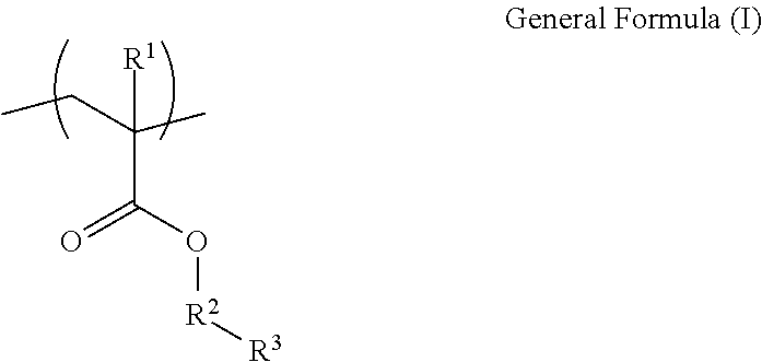
where, in the general formula (I), R1 represents a hydrogen atom or an alkyl group, R2 represents an alkylene group having 1 or more carbon atoms, and R3 represents a tertiary amino group; and
a structural unit (b) represented by general formula (II) below:

where, in the general formula (II), R4 represents a hydrogen atom or an alkyl group, R5 represents an alkylene group having 1 to 7 carbon atoms, both inclusive, or an alkylene oxide group having a total number of carbon and oxygen atoms of 1 or more and 7 or less, and R6 represents a hydrogen atom, a methyl group, or an ethyl group,
wherein a composition ratio (a:b) of the structural unit (a) represented by the general formula (I) and the structural unit (b) represented by the general formula (II) ranges from “more than 0 mol %:less than 100 mol %” to “100 mol % or less: 0 mol % or more”.
2. A liquid composition comprising:
at least one of a positive electrode active material and a solid electrolyte;
the binder according to claim 1; and
a solvent.
3. The liquid composition according to claim 2 , wherein the binder has a glass transition temperature of −30° C. or higher and less than 70° C.
4. The liquid composition according to claim 2 , wherein the positive electrode active material comprises at least one member selected from the group consisting of lithium-containing transition metal oxides and lithium-containing transition metal phosphate compounds.
5. The liquid composition according to claim 2 , wherein the positive electrode active material contains lithium.
6. The liquid composition according to claim 2 , wherein a content of the positive electrode active material is 10% by mass or more.
7. The liquid composition according to claim 2 , wherein the solid electrolyte is a sulfide solid electrolyte.
8. The liquid composition according to claim 2 , wherein the liquid composition has a viscosity of 200 mPa·s or less at 25° C.
9. The liquid composition according to claim 2 , wherein the liquid composition is an inkjet ink composition.
10. A storage container accommodating the liquid composition according to claim 2 .
11. An electrode production device comprising:
the storage container according to claim 10; and
an application unit that applies the liquid composition accommodated in the storage container onto an electrode base.
12. An electrode production method comprising applying the liquid composition according to claim 2 onto an electrode base.
13. The electrode production method according to claim 12 , further comprising pressurizing the electrode base to which the liquid composition has been applied.
14. An electrode comprising:
an electrode base; and
at least one of an electrode composite layer and a solid electrolyte layer on the electrode base, the at least one of an electrode composite layer and a solid electrolyte layer containing the binder according to claim 1 .
15. An electrochemical element comprising the electrode according to claim 14 .
16. A device comprising the electrochemical element according to claim 15 .
17. A moving body comprising the electrochemical element according to claim 15 .
Applications Claiming Priority (4)
| Application Number | Priority Date | Filing Date | Title |
|---|---|---|---|
| JP2023032470 | 2023-03-03 | ||
| JP2023-032470 | 2023-03-03 | ||
| JP2024003405A JP2024125167A (en) | 2023-03-03 | 2024-01-12 | Binder, liquid composition, storage container, electrode manufacturing apparatus, electrode manufacturing method, electrode, electrochemical element, device, and mobile body |
| JP2024-003405 | 2024-01-12 |
Publications (1)
| Publication Number | Publication Date |
|---|---|
| US20240297308A1 true US20240297308A1 (en) | 2024-09-05 |
Family
ID=92544408
Family Applications (1)
| Application Number | Title | Priority Date | Filing Date |
|---|---|---|---|
| US18/593,182 Pending US20240297308A1 (en) | 2023-03-03 | 2024-03-01 | Binder, liquid composition, storage container, electrode production device, electrode production method, electrode, electrochemical element, device, and moving body |
Country Status (1)
| Country | Link |
|---|---|
| US (1) | US20240297308A1 (en) |
-
2024
- 2024-03-01 US US18/593,182 patent/US20240297308A1/en active Pending
Similar Documents
| Publication | Publication Date | Title |
|---|---|---|
| CN108475817B (en) | Solid electrolyte composition and method for manufacturing all-solid-state secondary battery | |
| US9147880B2 (en) | Electrode active material containing polydopamine and lithium secondary battery including the same | |
| CN111194492A (en) | Solid electrolyte composition, solid electrolyte-containing sheet and all-solid-state secondary battery, and solid electrolyte-containing sheet and all-solid-state secondary battery manufacturing method | |
| KR101629489B1 (en) | Surface Treated Positive Active Material For Lithium Secondary Battery With Fluoropolymer and Method For Manufacturing The Same | |
| KR20200117014A (en) | Composition for electrode formation, method of manufacturing electrode, and method of manufacturing non-aqueous power storage element | |
| KR102567964B1 (en) | Lithium secondary battery | |
| KR20130118808A (en) | Electrolyte for secondary battery and lithium secondary battery comprising the same | |
| KR101481993B1 (en) | Electrode Comprising Compound Having Cyano group and Lithium Secondary Battery Comprising The Same | |
| KR20130118806A (en) | Electrolyte for secondary battery and lithium secondary battery comprising the same | |
| CN113258065A (en) | Liquid composition for forming electrochemical device, method for manufacturing electrode, method for manufacturing electrochemical device, and electrode | |
| KR101588624B1 (en) | Electrode of Improved Electrode Conductivity and Method For Manufacturing The Same | |
| KR101511022B1 (en) | Moisture-Limited Electrode Active Material, Moisture-Limited Electrode and Lithium Secondary Battery Comprising The Same | |
| KR20210029477A (en) | Method of pre-lithiation of electrode and apparatus therefor | |
| KR101514314B1 (en) | Electrode of Enhanced Adhesive Force and Lithium Secondary Battery Comprising The Same | |
| KR101572074B1 (en) | Anode Active Material Having High Capacity and Lithium Secondary Battery Comprising The Same | |
| KR101527532B1 (en) | Electrode Active Material Having Improved Lithium Diffusivity and Lithium Secondary Battery Comprising The Same | |
| JP2024125167A (en) | Binder, liquid composition, storage container, electrode manufacturing apparatus, electrode manufacturing method, electrode, electrochemical element, device, and mobile body | |
| KR20190143822A (en) | Lithium secondary battery | |
| US20240297308A1 (en) | Binder, liquid composition, storage container, electrode production device, electrode production method, electrode, electrochemical element, device, and moving body | |
| JP2023135606A (en) | Liquid composition, liquid composition for inkjet discharge, storage container, apparatus for producing electrochemical element members, apparatus for producing electrochemical elements, method for producing members for electrochemical elements, method for producing electrochemical elements, and electrochemical element | |
| US20220302454A1 (en) | Liquid composition, method for producing electrode, and method for producing electrochemical element | |
| US11749805B2 (en) | Liquid composition for forming electrochemical device, method of manufacturing electrodes, method of manufacturing electrochemical device and electrodes | |
| KR20150005867A (en) | Electrode Comprising Polyolefin Binder and Lithium Secondary Battery Comprising The Same | |
| KR101548117B1 (en) | Electrode Active Material of High Rate Capability and Lithium Secondary Battery Comprising The Same | |
| JP2022146892A (en) | Liquid composition, method for manufacturing electrode and method for manufacturing electrochemical element |
Legal Events
| Date | Code | Title | Description |
|---|---|---|---|
| AS | Assignment |
Owner name: RICOH COMPANY, LTD., JAPAN Free format text: ASSIGNMENT OF ASSIGNORS INTEREST;ASSIGNORS:SAGISAKA, TOSHIYA;OHYA, KAYATO;HIGASHI, RYUJI;AND OTHERS;SIGNING DATES FROM 20240227 TO 20240228;REEL/FRAME:066650/0322 |
|
| STPP | Information on status: patent application and granting procedure in general |
Free format text: DOCKETED NEW CASE - READY FOR EXAMINATION |