US2022400A - Collapsible portable carriage - Google Patents
Collapsible portable carriage Download PDFInfo
- Publication number
- US2022400A US2022400A US28070A US2807035A US2022400A US 2022400 A US2022400 A US 2022400A US 28070 A US28070 A US 28070A US 2807035 A US2807035 A US 2807035A US 2022400 A US2022400 A US 2022400A
- Authority
- US
- United States
- Prior art keywords
- supports
- seat
- frame
- undercarriage
- carriage
- Prior art date
- Legal status (The legal status is an assumption and is not a legal conclusion. Google has not performed a legal analysis and makes no representation as to the accuracy of the status listed.)
- Expired - Lifetime
Links
- 210000005069 ears Anatomy 0.000 description 6
- 238000003780 insertion Methods 0.000 description 4
- 230000037431 insertion Effects 0.000 description 4
- 235000012571 Ficus glomerata Nutrition 0.000 description 1
- 240000000365 Ficus racemosa Species 0.000 description 1
- 235000015125 Sterculia urens Nutrition 0.000 description 1
- 238000006073 displacement reaction Methods 0.000 description 1
- 238000012986 modification Methods 0.000 description 1
- 230000004048 modification Effects 0.000 description 1
- 230000036544 posture Effects 0.000 description 1
Images

Classifications
-
- B—PERFORMING OPERATIONS; TRANSPORTING
- B62—LAND VEHICLES FOR TRAVELLING OTHERWISE THAN ON RAILS
- B62B—HAND-PROPELLED VEHICLES, e.g. HAND CARTS OR PERAMBULATORS; SLEDGES
- B62B7/00—Carriages for children; Perambulators, e.g. dolls' perambulators
- B62B7/04—Carriages for children; Perambulators, e.g. dolls' perambulators having more than one wheel axis; Steering devices therefor
- B62B7/06—Carriages for children; Perambulators, e.g. dolls' perambulators having more than one wheel axis; Steering devices therefor collapsible or foldable
- B62B7/10—Carriages for children; Perambulators, e.g. dolls' perambulators having more than one wheel axis; Steering devices therefor collapsible or foldable by folding down the body to the wheel carriage or by retracting projecting parts into the box-shaped body
-
- B—PERFORMING OPERATIONS; TRANSPORTING
- B62—LAND VEHICLES FOR TRAVELLING OTHERWISE THAN ON RAILS
- B62B—HAND-PROPELLED VEHICLES, e.g. HAND CARTS OR PERAMBULATORS; SLEDGES
- B62B2205/00—Hand-propelled vehicles or sledges being foldable or dismountable when not in use
- B62B2205/04—Hand-propelled vehicles or sledges being foldable or dismountable when not in use box-shaped in folded position
Definitions
- This invention relates to a baby carriage collapsible into a handbag or valise so as to render it conveniently portable.
- baby carriages are so constructed as to be inherently bulky, cumbersome and space-consuming so that they are not adaptable for convenient transportation in a train, car or other vehicle. Because of the difficulties of carrying the carriage, parents are frequently prevented from making trips with their infants to points remote from their homes, being very often confined to their immediate neighborhoods. It is to overcome this disadvantage characteristic of the ordinary baby carriage that I have con- "cei-ved this invention, which contemplates the provision of a carriage which can be readily collapsed and folded up into the form of a compact valise, to make the entire device conveniently portable.
- Figure 1 is a perspective of the device constituting my invention shown collapsed into a handbag.
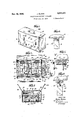
- Figure 2 is a plan view of the body of the device with the top side flaps open to show the assembled parts therein.
- Figure 3 is a vertical transversecross section of the structure constituting my invention with the undercarriage in collapsed form within the body thereof.
- Figure i is a perspective view of the body of the carriage and the wheeled understructure placed alongside thereof.
- Figure 5 a side sectional view of my invention assembled for operative use, showing an awning in place.
- Figure 6 is a fragmentary side sectional view of the front portion of the carriage showing the means of attaching the body to the undercarriage.
- Figure '7 is a fragmentary transverse section of further supported by the chains 25 and 26.
- Figure 8 is a fragmentary side section taken along line 8-8 of Figure '7. 5
- the body I0 is a separate unit adaptable for operative attachment to the undercarriage or wheeled chassis I l and the handlebar l2.
- the body is substantially box-like in shape, containing at the top thereof the two 10 hinged side flaps I3 and M and the hinged rear flap I5 which is adapted to serve as a back rest.
- the seat I6, mounted at the pivotal connection I! attached to the rear wall I8, is supported by the leg l9 pivotally attached to the seat at con- 15 nection 20,said leg being adapted to rest upon the bottom 2
- the front of the body contains the front wall or extensible foot rest 22 which is supported by the flexible side flaps 23 and 24,-this foot rest being adapted to be swung 20 outwardly into a horizontal position where it is
- the said foot rest is held in its vertical closed position by releasable locking members consisting of a pair of pivotally mounted latches 21 and 28 adapt- 25 ed for interlocking engagement with the notched fixed bars 29 and 30, respectively.
- the seat I6 is further provided with the two arms or side'rests 3
- the back rest l5 can be swung into its vertical position against the back rests and secured thereto by the operative engagement of the rotatable buttons 33 and 34 with the walls of the holes 35 and 36 contained within 35 the uprights 3'! and 38 of the side rests.
- the body I0 can be mounted directly upon the undercarriage or wheeled chassis H and secured thereto by operatively inserting the two bent hooks 39 (only one of which is shown) located at the front underside of the body into the two holes 40 and 4
- the rear attachment is effected by inserting into the 45 slotted apertures 43 and 44, in the transverse member 45 of the rear support, the two downwardly extending perforated ears 46 (only one shown in Figure D -said ears being preferably the terminal portions of the transverse bar 4'! at 50 the rear underside of the body.
- Pivotally attached to the center of the said transverse member 45 is the lever 48 to which are pivotally mounted the oppositely positioned bolts 49 and 50 extending through suitable apertures in the 55 lateral rear uprights 5i and 52. These bolts are adapted to be projected in opposite directions through the perforations 53 in said ears upon a manipulation of the lever 48 to lock the undercarriage to the body.
- the handlebar I2 is secured to the rear wall It of the body by inserting the terminals of the two vertical posts 55 thereof into the receiving ears 55 and 5'
- the pivotally mounted lever 59 has secured to the end thereof t.e flexible link or chain 59a which in turn is operatively connected to the transverse brake bar 66 through the links 6!, am, 62, 53 and 64,tli'e terminal portions of said brake bar being adaptable for engagement with the rims of the wheels t5 and 66 against the action of spring 68a, upon an upward pull upon the chain 59a effected by a downwardly manipulation of the lever 59.
- the awning 6'1 can be operatively attached to the body by applying the two lateral uprights 63 against the outer sides of the flaps l3 and I4, and operatively engaging the rotatable buttons 69 and T0 with the holes H or 12 in the uprights. It will be noted that when the holes 12 are employed for this purpose, the awning will be in a lowered position to render it adaptable for use when the child is in a reclining position, for which the device is adapted as will appear from the description hereinafter given. It will be further ob served that this arrangement enables the flaps l3 and M to remain vertically disposed inasmuch as they are held against lateral displacement between the said uprights 58 and the arms or side rests 3
- the seat I6 is so disposed as to enable the child to remain in a seated position.
- and 32 are folded inwardly in the direction of the arrows ( Figure 4) the leg l9 swung inwardly against the seat, and the seat swung downwardly against the rear wall I8 ( Figure 5).
- a pillow can then be placed against the collapsed seat, and the childs head permitted to recline thereagainst. In this event, it may be necessary to extend the foot rest downwardly to the horizontal position shown in dot-dash lines in Figure 5,-thereby providing additional leg space.
- the handlebar 59 is detached from wall l8 and placed within the body. Then the chain 59a is detached from the lever 59, the said front and rear supports folded down as aforesaid, and the undercarriage in this condition inserted into the bottom of the body; and thereafter the awning in its folded position placed thereover.
- the dimen- 6 sional design of the parts are such as to enable them all to fit snugly within the body. Thereafter the rear flap I5 is folded inwardly into a horizontal position, the side flaps l3 and it closed by means of the locks 84 and 85, and the front 10 wall 22 brought into its closed position and locked in place by means of the latch elements 2?, 28, 39 and 38.
- the entire structure is now contained within the folded body which assumes the shape of a portable handbag that can be conveniently 15 carried by the handle 86.
- a body containing two side flaps foldable over the top 80 opening to form a closure therefor, a pivotally supported seat at the rear wall of the body and foldable inwardly thereagainst, a back rest at the rear of the seat and foldable inwardly to lie adjacent said side flaps when in their folded posi- 3 tions;
- a Wheeled undercarriage containing a frame for supporting the wheels, front and rear upright supports collapsible downwardly against the frame, and releasable means for holding said supports in their collapsed positions;
- said under- 40 carriage being adaptable when collapsed to be inserted through said top opening into the body, the said uprights when in their operative positions being adapted to underlie and support said body, means for detachab-ly securing said sup- 45 ports to the body;
- a handlebar detachably secured to the rear wall of the body and adapted to be inserted through said top opening into the body, and a hand-gripping portion attached
- the front wall being pivotally attached to the bottom of the body, detachable means for holding said front wall in its closed vertical position against the body, means for supporting said front wall in a horizontal position substantially coextensive with the bottom of the body; and a wheeled undercarriage detachably
- a body containing two side flaps foldable horizontally over the top opening to form a closure therefor, means to releasably hold said flaps in their closed positions, said flaps being adapted for substantially vertical positioning, a seat pivotally secured to the rear wall of the body and foldable inwardly thereagainst, two normally vertically disposed arms pivotally mounted at the side edges of the seat and collapsible inwardly against the seat; an awning containing two uprights detachably cngageable with the outer surfaces of said side flaps to hold them in their vertical positions; a back rest at the rear of the seat and foldable inwardly to underlie said side flaps when in their folded positions; the bottom of said body being adapted for superimposition upon and releasable attachment to a suitable wheeled undercarriage, the rear wall being adapted for detachable engagement with a handlebar, and a side wall thereof having attached'thereto hand-gripping means.
- a wheeled undercarriage containing a horizontally disposed rectangular frame, four wheels suitably mounted thereon, a front and a rear support pivotally secured to the frame, spring means anchored to the frame and operatively engageable with said supports to normally hold them in their upright positions, said supports being swingable downwardly against said frame, releasable locking means for holding the supports in their collapsed positions against the frame; a body adapted for superimposition upon said supports, and means for detachably securing the body to the supports; the said undercarriage in its collapsed condition being adapted for insertion into said body through its top opening.
- a wheeled undercarriage containing a horizontally disposed rectangular frame, four wheels suitably mounted thereon, a front and a rear support pivotally secured to the frame, spring means anchored to the frame and operatively engageable with said supports to yieldably hold them in their normal upright positions, said supports being swingable downwardly against said frame, releasable looking means for holding the supports in their collapsed positions against the frame; braking means in operative relation to certain of said wheels, spring means to normally keep said braking means inoperative, pivotal means attached to said frame and operatively connected to said braking means for actuating same against the action of said spring means; a body adapted for superimposition upon said supports, means for detachably securing the body to the supports, a handlebar attached to the body, and a lever attached to the handlebar and connected to said pivotal means for operatively actuating same; the said undercarriage in its collapsed condition and the said handlebar being adapted for insertion into said
- a wheeled undercarriage containing a horizontally disposed rectangular frame, four wheels suitably mounted thereon, a front and a rear support collapsible downwardly against the frame, releasable means for holding said supports in their collapsed positions against the frame;
- said supports containing transverse members each having a plurality of apertures therein, a lever pivotally mounted on one of said transverse members, two oppositely positioned bolts extending longitudinally with respect to the transverse member and pivotally secured to said lever at opposite sides of its pivotal mounting so that upon the operative manipulation of the lever the bolts will be projected outwardly in opposite directions;
- a body adapted to be mounted upon said supports, releasable locking means projecting downwardly from the bottom of said body and adapted to extend through said apertures for operative engagement with said transverse members, and two perforated ears extending downwardly from the bottom of said body and positioned to receive said bolts when projected outwardly by the said manipulation of the lever;
- a wheeled undercarriage containing a horizontally disposed rectangular frame, four wheels suitably mounted thereon, a front and a rear support pivotally secured to the frame, spring means anchored to the frame and operatively engageable with said supports to yieldably hold them in their normal upright positions; said supports being swingable downwardly against said frame, releasable looking means for holding the supports in their collapsed positions against the frame; said supports containing transverse members each having a plurality of apertures therein, a lever pivotally mounted on one of said transverse members, two oppositely positioned bolts extending longitudinally with respect to the transverse member and pivotally secured to said lever at opposite sides of its pivotal mounting so that upon the operative manipulation of the lever the bolts will be projected outwardly in opposite directions; a body adapted to be mounted upon said supports, releasable locking means projecting downwardly from the bottom of said body and adapted to extend through said apertures for operative engagement with said transverse members, and two per
Landscapes
- Engineering & Computer Science (AREA)
- Chemical & Material Sciences (AREA)
- Combustion & Propulsion (AREA)
- Transportation (AREA)
- Mechanical Engineering (AREA)
- Carriages For Children, Sleds, And Other Hand-Operated Vehicles (AREA)
Description
Nov. 26, 1935. J. BLOOM COLLAPSIBLE PORTABLE CARRIAGE 2 Sheets-Sheet 1 iled June 24, 1955 YINVEINTOR Jacob Bloom EJQP ATTORNEY Nov. 26, 1935. J. BLOOM I COLLAPSIBLE PORTABLE CARRIAGE Filed June 24, 1935 2 Sheets-Sheet 2 INVENTOR Janob Bloom B ATTORNEY Patented Nov. 26, 1935 UNITED STATES PATENT OFFICE 8 Claims.
This invention relates to a baby carriage collapsible into a handbag or valise so as to render it conveniently portable.
As is apparent, baby carriages are so constructed as to be inherently bulky, cumbersome and space-consuming so that they are not adaptable for convenient transportation in a train, car or other vehicle. Because of the difficulties of carrying the carriage, parents are frequently prevented from making trips with their infants to points remote from their homes, being very often confined to their immediate neighborhoods. It is to overcome this disadvantage characteristic of the ordinary baby carriage that I have con- "cei-ved this invention, which contemplates the provision of a carriage which can be readily collapsed and folded up into the form of a compact valise, to make the entire device conveniently portable.
It is another object of my invention to provide a vehicle for infants-containing adjustable elements for permitting the child to be positioned in either seated or reclining postures, and to enable an awning to be adjustably attached to the device for operative use whether the child is seated or reclining in the carriage.
It is still a further object of this invention to enable the device to be readily and quickly assembled by a person not possessing any special mechanical aptitude or skill.
Other objects, features and advantages will appear from the drawings and description hereinafter given.
Referring to the drawings,
Figure 1 is a perspective of the device constituting my invention shown collapsed into a handbag.
Figure 2 is a plan view of the body of the device with the top side flaps open to show the assembled parts therein.
Figure 3 is a vertical transversecross section of the structure constituting my invention with the undercarriage in collapsed form within the body thereof.
Figure i is a perspective view of the body of the carriage and the wheeled understructure placed alongside thereof.
Figure 5 a side sectional view of my invention assembled for operative use, showing an awning in place.
Figure 6 is a fragmentary side sectional view of the front portion of the carriage showing the means of attaching the body to the undercarriage.
Figure '7 is a fragmentary transverse section of further supported by the chains 25 and 26.
the rear of the device showing the connecting means between the body and the undercarriage, and
Figure 8 is a fragmentary side section taken along line 8-8 of Figure '7. 5
In the drawings, the body I0 is a separate unit adaptable for operative attachment to the undercarriage or wheeled chassis I l and the handlebar l2. The body is substantially box-like in shape, containing at the top thereof the two 10 hinged side flaps I3 and M and the hinged rear flap I5 which is adapted to serve as a back rest. The seat I6, mounted at the pivotal connection I! attached to the rear wall I8, is supported by the leg l9 pivotally attached to the seat at con- 15 nection 20,said leg being adapted to rest upon the bottom 2| of the body. The front of the body contains the front wall or extensible foot rest 22 which is supported by the flexible side flaps 23 and 24,-this foot rest being adapted to be swung 20 outwardly into a horizontal position where it is The said foot rest is held in its vertical closed position by releasable locking members consisting of a pair of pivotally mounted latches 21 and 28 adapt- 25 ed for interlocking engagement with the notched fixed bars 29 and 30, respectively. The seat I6 is further provided with the two arms or side'rests 3| and 32 pivotally mounted on the seat at the side edges thereof. When the said side rests are 30 in their upright positions, the back rest l5 can be swung into its vertical position against the back rests and secured thereto by the operative engagement of the rotatable buttons 33 and 34 with the walls of the holes 35 and 36 contained within 35 the uprights 3'! and 38 of the side rests.
By referring to Figures 4, 5 and 6 it will be seen that the body I0 can be mounted directly upon the undercarriage or wheeled chassis H and secured thereto by operatively inserting the two bent hooks 39 (only one of which is shown) located at the front underside of the body into the two holes 40 and 4| in the transverse member 32 of the front support of the chassis. The rear attachment is effected by inserting into the 45 slotted apertures 43 and 44, in the transverse member 45 of the rear support, the two downwardly extending perforated ears 46 (only one shown in Figure D -said ears being preferably the terminal portions of the transverse bar 4'! at 50 the rear underside of the body. Pivotally attached to the center of the said transverse member 45 is the lever 48 to which are pivotally mounted the oppositely positioned bolts 49 and 50 extending through suitable apertures in the 55 lateral rear uprights 5i and 52. These bolts are adapted to be projected in opposite directions through the perforations 53 in said ears upon a manipulation of the lever 48 to lock the undercarriage to the body.
The handlebar I2 is secured to the rear wall It of the body by inserting the terminals of the two vertical posts 55 thereof into the receiving ears 55 and 5'|,-the rotatable buttons 58, of which there are two secured to the rear wall l8 of the body, being operatively engageable with corresponding holes in the transverse bar 5512 connecting the two posts 55. The pivotally mounted lever 59 has secured to the end thereof t.e flexible link or chain 59a which in turn is operatively connected to the transverse brake bar 66 through the links 6!, am, 62, 53 and 64,tli'e terminal portions of said brake bar being adaptable for engagement with the rims of the wheels t5 and 66 against the action of spring 68a, upon an upward pull upon the chain 59a effected by a downwardly manipulation of the lever 59.
The awning 6'1 can be operatively attached to the body by applying the two lateral uprights 63 against the outer sides of the flaps l3 and I4, and operatively engaging the rotatable buttons 69 and T0 with the holes H or 12 in the uprights. It will be noted that when the holes 12 are employed for this purpose, the awning will be in a lowered position to render it adaptable for use when the child is in a reclining position, for which the device is adapted as will appear from the description hereinafter given. It will be further ob served that this arrangement enables the flaps l3 and M to remain vertically disposed inasmuch as they are held against lateral displacement between the said uprights 58 and the arms or side rests 3| and 32.
As is apparent from Figures 4 and 5, the seat I6 is so disposed as to enable the child to remain in a seated position. Should it be desired to place the infant in a reclining position, the arms 3| and 32 are folded inwardly in the direction of the arrows (Figure 4) the leg l9 swung inwardly against the seat, and the seat swung downwardly against the rear wall I8 (Figure 5). A pillow can then be placed against the collapsed seat, and the childs head permitted to recline thereagainst. In this event, it may be necessary to extend the foot rest downwardly to the horizontal position shown in dot-dash lines in Figure 5,-thereby providing additional leg space.
In collapsing the undercarriage, the front support I l is folded downwardly against the recta:
the uprights 5| and 52, the transverse member and attached parts are swung downwardly thereover,the pivotally mounted locking member M being brought into locking engagement with the pin l5. It will be noticed that the spring E5 attached to the upright 52 holds the notch in said member 14 in constant engagement with the shank of the pin '55. The springs Ti and I8, suitably attached to the framework :73, are connected with the terminals 19 and at} of the front and rear supports respectively,-these supports being pivotally mounted on the frame '53 at 8| and 82 respectively. It is thus apparent that upon a release of the locking member 14 against the actionof spring E5, the springs I! and I8 will urge the said front and rear supports upwardly into their vertical operative positions.
To collapse this device into a handbag, the handlebar 59 is detached from wall l8 and placed within the body. Then the chain 59a is detached from the lever 59, the said front and rear supports folded down as aforesaid, and the undercarriage in this condition inserted into the bottom of the body; and thereafter the awning in its folded position placed thereover. The dimen- 6 sional design of the parts are such as to enable them all to fit snugly within the body. Thereafter the rear flap I5 is folded inwardly into a horizontal position, the side flaps l3 and it closed by means of the locks 84 and 85, and the front 10 wall 22 brought into its closed position and locked in place by means of the latch elements 2?, 28, 39 and 38. The entire structure is now contained within the folded body which assumes the shape of a portable handbag that can be conveniently 15 carried by the handle 86.
It is apparent that the structure is such as to enable a person without any special mechanical aptitude to very readily assemble this device for operative use. 20
It is of course understood that the various embodiments above described and shown in the drawings are illustrative of my invention and not employed by way of limitation, inasmuch as numerous changes and modifications may be made 25 within the scope of the appended claims with out departing from the spirit of this invention.
What I claim is:
1. In a collapsible portable carriage, a body containing two side flaps foldable over the top 80 opening to form a closure therefor, a pivotally supported seat at the rear wall of the body and foldable inwardly thereagainst, a back rest at the rear of the seat and foldable inwardly to lie adjacent said side flaps when in their folded posi- 3 tions; a Wheeled undercarriage containing a frame for supporting the wheels, front and rear upright supports collapsible downwardly against the frame, and releasable means for holding said supports in their collapsed positions; said under- 40 carriage being adaptable when collapsed to be inserted through said top opening into the body, the said uprights when in their operative positions being adapted to underlie and support said body, means for detachab-ly securing said sup- 45 ports to the body; a handlebar detachably secured to the rear wall of the body and adapted to be inserted through said top opening into the body, and a hand-gripping portion attached to one of the sides of the body. 50
2. In a collapsible portable carriage, a body containing two side flaps foldable horizontally over the top opening to form a closure therefor, means to releasably hold said flaps in their closed positions, said flaps being adapted for substantially vertical positioning, means to hold the flaps in their vertical positions; a seat pivotally secured to the rear wall of the body and foldable inwardly thereagainst, an arm on either side of the seat and foldable thereagainst, a back rest 60 pivotally mounted on the rear wall of the body and adapted for vertical positioning at the rear of the seat and against said arms, means for releasably securing said back rest to said arms, said back rest being foldable inwardly to underlie 65 said side flaps when in their folded positions; the'bottom of said body being adapted for superimposition upon and releasable attachment to a suitable wheeled undercarriage, the rear wall being adapted for detachable engagement with a 70 handlebar, and a side wall thereof having at tached thereto hand-gripping means.
3. In a collapsible portable carriage, a body containing two side flaps foldable horizontally over the top opening to form a closure therefor,
means to releasably hold said flaps in their closed positions; said flaps being adapted for substantially vertical postioning; a seat pivotally secured to the rear Wall of the body and foldable inwardly thereagainst, two arms pivotally mounted at the side edges of the seat and swingably movable into their collapsed positions against the seat, seat-supporting means pivotally mounted at the front edge of the seat and foldable inwardly against the underside thereof, a bacl: rest pivotally mounted on the rear wall of the body and adapted for vertical positioning at the rear of the seat and against said arms, means for releasably securing said back rest to said arms, said back rest being foldable inwardly to underlie said side flaps when in their folded positions; the front wall being pivotally attached to the bottom of the body, detachable means for holding said front wall in its closed vertical position against the body, means for supporting said front wall in a horizontal position substantially coextensive with the bottom of the body; and a wheeled undercarriage detachably secured to said bottom of the body.
4. In a collapsible portable carriage, a body containing two side flaps foldable horizontally over the top opening to form a closure therefor, means to releasably hold said flaps in their closed positions, said flaps being adapted for substantially vertical positioning, a seat pivotally secured to the rear wall of the body and foldable inwardly thereagainst, two normally vertically disposed arms pivotally mounted at the side edges of the seat and collapsible inwardly against the seat; an awning containing two uprights detachably cngageable with the outer surfaces of said side flaps to hold them in their vertical positions; a back rest at the rear of the seat and foldable inwardly to underlie said side flaps when in their folded positions; the bottom of said body being adapted for superimposition upon and releasable attachment to a suitable wheeled undercarriage, the rear wall being adapted for detachable engagement with a handlebar, and a side wall thereof having attached'thereto hand-gripping means.
5. In a collapsible portable carriage, a wheeled undercarriage containing a horizontally disposed rectangular frame, four wheels suitably mounted thereon, a front and a rear support pivotally secured to the frame, spring means anchored to the frame and operatively engageable with said supports to normally hold them in their upright positions, said supports being swingable downwardly against said frame, releasable locking means for holding the supports in their collapsed positions against the frame; a body adapted for superimposition upon said supports, and means for detachably securing the body to the supports; the said undercarriage in its collapsed condition being adapted for insertion into said body through its top opening.
6. In a collapsible portable carriage, a wheeled undercarriage containing a horizontally disposed rectangular frame, four wheels suitably mounted thereon, a front and a rear support pivotally secured to the frame, spring means anchored to the frame and operatively engageable with said supports to yieldably hold them in their normal upright positions, said supports being swingable downwardly against said frame, releasable looking means for holding the supports in their collapsed positions against the frame; braking means in operative relation to certain of said wheels, spring means to normally keep said braking means inoperative, pivotal means attached to said frame and operatively connected to said braking means for actuating same against the action of said spring means; a body adapted for superimposition upon said supports, means for detachably securing the body to the supports, a handlebar attached to the body, and a lever attached to the handlebar and connected to said pivotal means for operatively actuating same; the said undercarriage in its collapsed condition and the said handlebar being adapted for insertion into said body through its top opening.
7. In a collapsible portable carriage, a wheeled undercarriage containing a horizontally disposed rectangular frame, four wheels suitably mounted thereon, a front and a rear support collapsible downwardly against the frame, releasable means for holding said supports in their collapsed positions against the frame; said supports containing transverse members each having a plurality of apertures therein, a lever pivotally mounted on one of said transverse members, two oppositely positioned bolts extending longitudinally with respect to the transverse member and pivotally secured to said lever at opposite sides of its pivotal mounting so that upon the operative manipulation of the lever the bolts will be projected outwardly in opposite directions; a body adapted to be mounted upon said supports, releasable locking means projecting downwardly from the bottom of said body and adapted to extend through said apertures for operative engagement with said transverse members, and two perforated ears extending downwardly from the bottom of said body and positioned to receive said bolts when projected outwardly by the said manipulation of the lever; the said undercarriage in its collapsed condition being adapted for insertion into said body through its top opening.
8. In a collapsible portable carriage, a wheeled undercarriage containing a horizontally disposed rectangular frame, four wheels suitably mounted thereon, a front and a rear support pivotally secured to the frame, spring means anchored to the frame and operatively engageable with said supports to yieldably hold them in their normal upright positions; said supports being swingable downwardly against said frame, releasable looking means for holding the supports in their collapsed positions against the frame; said supports containing transverse members each having a plurality of apertures therein, a lever pivotally mounted on one of said transverse members, two oppositely positioned bolts extending longitudinally with respect to the transverse member and pivotally secured to said lever at opposite sides of its pivotal mounting so that upon the operative manipulation of the lever the bolts will be projected outwardly in opposite directions; a body adapted to be mounted upon said supports, releasable locking means projecting downwardly from the bottom of said body and adapted to extend through said apertures for operative engagement with said transverse members, and two perforated ears extending downwardly from the bottom of said body and positioned to receive said bolts when projected outwardly by the said manipulation of the lever; the said undercarriage in its collapsed condition being adapted for insertion into said body through its top opening.
JACOB BLOOM.
Priority Applications (1)
| Application Number | Priority Date | Filing Date | Title |
|---|---|---|---|
| US28070A US2022400A (en) | 1935-06-24 | 1935-06-24 | Collapsible portable carriage |
Applications Claiming Priority (1)
| Application Number | Priority Date | Filing Date | Title |
|---|---|---|---|
| US28070A US2022400A (en) | 1935-06-24 | 1935-06-24 | Collapsible portable carriage |
Publications (1)
| Publication Number | Publication Date |
|---|---|
| US2022400A true US2022400A (en) | 1935-11-26 |
Family
ID=21841404
Family Applications (1)
| Application Number | Title | Priority Date | Filing Date |
|---|---|---|---|
| US28070A Expired - Lifetime US2022400A (en) | 1935-06-24 | 1935-06-24 | Collapsible portable carriage |
Country Status (1)
| Country | Link |
|---|---|
| US (1) | US2022400A (en) |
Cited By (1)
| Publication number | Priority date | Publication date | Assignee | Title |
|---|---|---|---|---|
| US2903270A (en) * | 1957-10-21 | 1959-09-08 | Ross David | Combined stroller and carrying case |
-
1935
- 1935-06-24 US US28070A patent/US2022400A/en not_active Expired - Lifetime
Cited By (1)
| Publication number | Priority date | Publication date | Assignee | Title |
|---|---|---|---|---|
| US2903270A (en) * | 1957-10-21 | 1959-09-08 | Ross David | Combined stroller and carrying case |
Similar Documents
| Publication | Publication Date | Title |
|---|---|---|
| US4725071A (en) | Tandem stroller | |
| US3669492A (en) | Reclining car seat | |
| US2720911A (en) | Convertible baby stroller and child's seat for automobiles | |
| US3000645A (en) | Extra passenger attachments for infants' vehicles and the like | |
| US4836573A (en) | Combination infant stroller and baby bassinet | |
| US3574872A (en) | Infant{3 s car bed | |
| US5622375A (en) | Push-chair | |
| US3572827A (en) | Child{3 s car seat | |
| JPH04143167A (en) | Reclining or lying posture mechanism of baby car and the like | |
| US2337505A (en) | Convertible passenger car and ambulance | |
| US5911432A (en) | Two seat baby carriage | |
| US4934722A (en) | Folding wheelchair | |
| US2098469A (en) | Foldable enclosure | |
| US6464244B1 (en) | Stroller assembly having a foldable frame | |
| US2754889A (en) | Wheeled bassinet convertible to high chair and other infant devices | |
| US2625407A (en) | Foldable wheeled vehicle for infants | |
| US2770288A (en) | Combination high chair and vehicle | |
| US2433504A (en) | Collapsible infant berth | |
| US2730163A (en) | Convertible bassinet and child's chair for automobiles | |
| US2022400A (en) | Collapsible portable carriage | |
| US3094339A (en) | Convertible baby carriage | |
| US1355039A (en) | Convertible chair and carriage | |
| PT9329U (en) | BABY BOOTS-BABY CHAIRS | |
| US2917316A (en) | Collapsible stroller | |
| US2002607A (en) | Folding crib |