US20220417841A1 - Demarcating User-Mediated and Carrier-Mediated Connections - Google Patents
Demarcating User-Mediated and Carrier-Mediated Connections Download PDFInfo
- Publication number
- US20220417841A1 US20220417841A1 US17/756,602 US201917756602A US2022417841A1 US 20220417841 A1 US20220417841 A1 US 20220417841A1 US 201917756602 A US201917756602 A US 201917756602A US 2022417841 A1 US2022417841 A1 US 2022417841A1
- Authority
- US
- United States
- Prior art keywords
- vpn
- network
- mobile device
- wireless network
- user
- Prior art date
- Legal status (The legal status is an assumption and is not a legal conclusion. Google has not performed a legal analysis and makes no representation as to the accuracy of the status listed.)
- Abandoned
Links
Images


Classifications
-
- H—ELECTRICITY
- H04—ELECTRIC COMMUNICATION TECHNIQUE
- H04L—TRANSMISSION OF DIGITAL INFORMATION, e.g. TELEGRAPHIC COMMUNICATION
- H04L12/00—Data switching networks
- H04L12/28—Data switching networks characterised by path configuration, e.g. LAN [Local Area Networks] or WAN [Wide Area Networks]
- H04L12/46—Interconnection of networks
- H04L12/4641—Virtual LANs, VLANs, e.g. virtual private networks [VPN]
-
- H—ELECTRICITY
- H04—ELECTRIC COMMUNICATION TECHNIQUE
- H04W—WIRELESS COMMUNICATION NETWORKS
- H04W12/00—Security arrangements; Authentication; Protecting privacy or anonymity
- H04W12/60—Context-dependent security
- H04W12/69—Identity-dependent
- H04W12/72—Subscriber identity
-
- H—ELECTRICITY
- H04—ELECTRIC COMMUNICATION TECHNIQUE
- H04W—WIRELESS COMMUNICATION NETWORKS
- H04W48/00—Access restriction; Network selection; Access point selection
- H04W48/18—Selecting a network or a communication service
-
- H—ELECTRICITY
- H04—ELECTRIC COMMUNICATION TECHNIQUE
- H04W—WIRELESS COMMUNICATION NETWORKS
- H04W88/00—Devices specially adapted for wireless communication networks, e.g. terminals, base stations or access point devices
- H04W88/02—Terminal devices
- H04W88/06—Terminal devices adapted for operation in multiple networks or having at least two operational modes, e.g. multi-mode terminals
Definitions
- This disclosure relates to demarcating user-mediated network and carrier-mediated network connections.
- Mobile devices e.g., smart phones
- other user devices typically offer a host of different wireless connection technologies (e.g., cellular, Wi-Fi, Bluetooth, etc.).
- MNOs mobile network operators
- MNVOs mobile virtual network operators
- MNOs mobile network operators
- MNVOs mobile virtual network operators
- 4G, 5G, etc. off-loading customer mobile data off cellular connections
- Modern mobile operating systems do not clearly distinguish between these carrier-mediated network connection and user-mediated network connections and instead offer control over connections to the mobile device on a radio-by-radio basis.
- the method includes, for a mobile device simultaneously connected to a first wireless network and a second wireless network, determining, by data processing hardware of the mobile device, whether the first wireless network is associated with a same network operator as the second wireless network.
- the method also includes establishing, by the data processing hardware, a virtual private network (VPN) between the mobile device and a remote server.
- the VPN includes a first VPN connection and a second VPN connection.
- the first VPN connection connects the mobile device to the remote server over the first wireless network and the second VPN connection connects the mobile device to the remote server over the second wireless network.
- the method also includes transmitting, by the data processing hardware, data from the mobile device to the remote server over the VPN via one of the first VPN connection or the second VPN connection.
- the data when received by the remote server, causes the remote server to route the data to a destination server.
- Implementations of the disclosure may include one or more of the following optional features.
- the first wireless network includes a cellular network and the second wireless network includes a wireless fidelity (Wi-Fi) network.
- Wi-Fi wireless fidelity
- the network operator when the first wireless network is associated with the same network operator as the second wireless network, the network operator includes a mobile virtual network operator.
- the network operator may include a mobile network operator.
- the first VPN connection and the second VPN connection each include carrier-mediated network connections.
- the method may include connecting, by the data processing hardware, the mobile device to a third wireless network.
- the third wireless network is associated with a different network operator than the network operator of the first and second wireless networks.
- the method may also include prompting, by the data processing hardware, a user of the mobile device to provide consent to permit the VPN to establish a third VPN connection connecting the mobile device to the remote server over the third wireless network.
- the method may include updating, by the data processing hardware, the VPN by establishing the third VPN connection connecting the mobile device to the remote server over the third wireless network.
- prompting the user of the mobile device to provide the consent to permit the VPN to establish the third VPN connection includes displaying a graphical element in a graphical user interface executing on the data processing hardware.
- the graphical element enables the user to provide the consent to permit the VPN to establish the third VPN connection.
- the third wireless network includes a user-mediated network. Determining whether the first wireless network is associated with the same network operator as the second wireless network, in some implementations, includes querying an application executing on the mobile device to determine whether the first wireless network is associated with the same network operator as the second wireless network.
- the application is verified via a subscriber identification module (SIM) of the mobile device.
- Transmitting the data from the mobile device to the remote server over the VPN may include transmitting a session token from the mobile device to the remote server over the VPN via the one of the first VPN connection or the second VPN connection.
- the data and session token when received by the remote server causes the remote server to identify the mobile device using the session token and route the data to the destination server.
- the remote server may also transmit response data received from the destination server to the mobile device over the VPN via the one of the first VPN connection or the second VPN connection.
- establishing the VPN causes the remote server to apply a network policy to both the first wireless network and the second wireless network.
- the network policy may include at least one of zero-rating or throttling.
- the method includes prompting, by the data processing hardware, a user of the mobile device to provide consent to establish the VPN between the mobile device and the remote server.
- the method may also include, when the user of the mobile device provides the consent to establish the VPN between the mobile device and the remote server, establishing, by the data processing hardware, the VPN between the mobile device and the remote server.
- the system includes data processing hardware and memory hardware of a mobile device in communication with the data processing hardware.
- the memory hardware stores instructions that when executed on the data processing hardware cause the data processing hardware to perform operations.
- the operations include, for the mobile device simultaneously connected to a first wireless network and a second wireless network, determining whether the first wireless network is associated with a same network operator as the second wireless network.
- the operations also include establishing a virtual private network (VPN) between the mobile device and a remote server.
- the VPN includes a first VPN connection and a second VPN connection.
- the first VPN connection connects the mobile device to the remote server over the first wireless network and the second VPN connection connects the mobile device to the remote server over the second wireless network.
- the operations also include transmitting data from the mobile device to the remote server over the VPN via one of the first VPN connection or the second VPN connection.
- the data when received by the remote server, causes the remote server to route the data to a destination server.
- the first wireless network includes a cellular network and the second wireless network includes a wireless fidelity (Wi-Fi) network.
- Wi-Fi wireless fidelity
- the network operator when the first wireless network is associated with the same network operator as the second wireless network, the network operator includes a mobile virtual network operator.
- the network operator may include a mobile network operator.
- the first VPN connection and the second VPN connection each include carrier-mediated network connections.
- the operations may include connecting the mobile device to a third wireless network.
- the third wireless network is associated with a different network operator than the network operator of the first and second wireless networks.
- the operations may also include prompting a user of the mobile device to provide consent to permit the VPN to establish a third VPN connection connecting the mobile device to the remote server over the third wireless network.
- the operations may include updating the VPN by establishing the third VPN connection connecting the mobile device to the remote server over the third wireless network.
- prompting the user of the mobile device to provide the consent to permit the VPN to establish the third VPN connection includes displaying a graphical element in a graphical user interface executing on the data processing hardware.
- the graphical element enables the user to provide the consent to permit the VPN to establish the third VPN connection.
- the third wireless network includes a user-mediated network. Determining whether the first wireless network is associated with the same network operator as the second wireless network, in some implementations, includes querying an application executing on the mobile device to determine whether the first wireless network is associated with the same network operator as the second wireless network.
- the application is verified via a subscriber identification module (SIM) of the mobile device.
- Transmitting the data from the mobile device to the remote server over the VPN may include transmitting a session token from the mobile device to the remote server over the VPN via the one of the first VPN connection or the second VPN connection.
- the data and session token when received by the remote server causes the remote server to identify the mobile device using the session token and route the data to the destination server.
- the remote server may also transmit response data received from the destination server to the mobile device over the VPN via the one of the first VPN connection or the second VPN connection.
- establishing the VPN causes the remote server to apply a network policy to both the first wireless network and the second wireless network.
- the network policy may include at least one of zero-rating or throttling.
- the operations include prompting a user of the mobile device to provide consent to establish the VPN between the mobile device and the remote server.
- the operations may also include, when the user of the mobile device provides the consent to establish the VPN between the mobile device and the remote server, establishing the VPN between the mobile device and the remote server.
- FIG. 1 is a schematic view of an example system for demarcating user-mediated and carrier-mediated connections and providing a multi-network between the different connections.
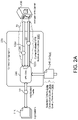
- FIGS. 2 A- 2 C are schematic views of exemplary components of a connection aggregator.
- FIG. 2 D is a schematic view of an interactive graphic rendered on a graphical user interface executing on a mobile device.
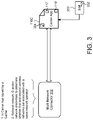
- FIG. 3 is a schematic view of a multi-network connector.
- FIGS. 4 A and 4 B are schematic views of interactive graphics rendered on a graphical user interface executing on a mobile device.
- FIG. 5 is a flowchart of an example arrangement of operations for a method of demarcating and connecting carrier-mediated networks and user-mediated networks.
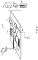
- FIG. 6 is a schematic view of an example computing device that may be used to implement the systems and methods described herein.
- Carriers such as mobile network operators (MNOs) and mobile virtual network operators (MVNOs), are increasingly providing connectivity via multiple heterogeneous network types (e.g., cellular networks and Wi-Fi networks).
- Current mobile operating systems (OS) do not distinguish clearly between connections that are user-mediated (such as a home Wireless Fidelity (Wi-Fi) network) and carrier-mediated connections, such as a Wi-Fi access point with credentials provided by a carrier or a cellular connection controlled by the carrier (e.g., LTE).
- User-mediate networks and carrier-mediated networks may have very different properties, and therefore treating the two classes of networks the same often leads to suboptimal user experiences.
- a carrier may desire to provide session mobility to improve the user experience by tunneling user traffic through a virtual private network (VPN), but cannot do so without clear demarcation between carrier-mediated networks and user-mediated networks.
- the carrier may not be able to include user-mediated networks within the VPN (e.g., for privacy concerns).
- mobile devices typically have user controls for allowing the user to manage radios on the mobile device.
- the user may enable/disable the Wi-Fi radio or enable/disable the mobile (i.e., cellular) data radio.
- the mobile devices also provide status indicators on a radio-by-radio basis rather than on a carrier or operator basis.
- a user of the mobile device may desire to temporarily disable connectivity from their carrier, which may include elements of multiple different wireless connections (e.g., both Wi-Fi and cellular), but the mobile device lacks any convenient way to do so.
- the user must disable connectivity on a radio-by-radio basis, which disables all connections from that radio. This may have unintended consequences.
- disabling a Wi-Fi radio to prevent the mobile device from connecting to a Wi-Fi network provided by a carrier will also prevent connections to other Wi-Fi connections (e.g., to the user's home network) that are not managed by that carrier.
- the mobile device provides visual indicators of radio connectivity (e.g., Wi-Fi or cellular connection strength), but not carrier connectivity. For example, there is no way to discern whether Wi-Fi strength graphical status indicator is associated with a user-mediated Wi-Fi network or a carrier-mediated Wi-Fi network.
- Implementations herein are directed toward a connection aggregator 200 and a multi-network controller 300 that both execute on a user device 110 for demarcating user-mediated networks from carrier-mediated networks and providing a convenient user input and visual indication to control and report multi-network connectivity.
- the user device 110 may be interchangeably referred to as user equipment (UE) or a mobile device.
- UE user equipment
- an example wireless communication environment 100 includes the mobile device 110 in communication with an external network 40 through multiple wireless networks 120 , 120 a - n .
- the user device 110 may communicate with the external network 40 via a cellular network 120 a and a Wi-Fi network 120 b .
- the cellular network 120 a may include a General Packet Radio Service (GPRS) network, a Universal Mobile Telecommunications System (UMTS) network, a High Speed Packet Access (HSPA) network, an enhanced-HSPA (H+) network, an Enhanced Data Rates for Global System for Mobile communications (GSM) (EDGE) network, or a Long-Term Evolution (LTE) radio access network (RAN) (e.g., 4G/5G LTE) that supports radio communication of data packets 50 and/or other services from the external network 40 to the user device 110 via, for example, base stations such as macro-cell evolved Node B's (MeNB).
- GPRS General Packet Radio Service
- UMTS Universal Mobile Telecommunications System
- HSPA High Speed Packet Access
- H+ enhanced-HSPA
- GSM Global System for Mobile communications
- EDGE Enhanced Data Rates for Global System for Mobile communications
- LTE Long-Term Evolution
- RAN e.g., 4G/5G LTE
- the Wi-Fi network 120 b may include any version of Wi-Fi (e.g., 802.11n, 802.11ac, etc.) that also supports radio communication of the data packets 50 .
- the user device 110 connects to multiple wireless networks 120 of the same type simultaneously.
- the user device 110 may include capabilities for simultaneously connecting to two separate cellular networks 120 a operated by different carriers 70 .
- the cellular network 120 a is associated with a mobile network operator (MNO) or a mobile virtual network operator (MNVO) that provides services of wireless communications to the subscribing user device 110 via the cellular network 120 a .
- MNO mobile network operator
- MNVO mobile virtual network operator
- the MNO or MVNO may also be referred to as a wireless service provider, wireless carrier, cellular company, mobile network operator, or mobile network carrier.
- carrier may be used herein to refer to the MNO or MVNO.
- network operator may be used herein to refer to an entity that operates or mediates a wireless network 120 , which may include a carrier (e.g., an MNO or MVNO) that operates/mediates a carrier-mediated wireless network 120 or a user 10 that operates/mediates a user-mediated wireless network 120 .
- a carrier e.g., an MNO or MVNO
- a carrier-mediated wireless network 120 includes any wireless network 120 managed or mediated or controlled by a single particular carrier 70 (e.g., an MNO or MVNO) where the user device 110 subscribes to a service provided by the carrier. That is, the user 10 does not control or manage the wireless network 120 .
- a carrier-mediated network 120 is a network for which a carrier has provided credentials, such as where either a carrier-provided SIM profile or a carrier-provided application which can be authenticated by the carrier-provided SIM profile, has provided credentials.
- a SIM profile provided on a UICC allows the user device 110 to attach and authenticate with a cellular network 120 .
- the carrier application is authenticated by the operating system 111 to access the SIM profile.
- the carrier application may be cryptographically signed with the carrier's private key and authenticated via the signature of the application contained in the SIM profile.
- the carrier application is authorized by the operating system 111 to provide credentials for accessing, for example, Wi-Fi access points.
- the authenticated carrier application may provide a WPA password or a Hotspot2.0 certificate; or, for an open network where credentials are not needed to connect to the access point, the carrier causes the user device 110 to connect to the access point without need for user intervention, or causes a suggestion to connect to the network to be made to the user, which the user can accept or reject.
- an additional step may be needed to bypass a “captive portal” to gain internet access, such as accepting terms and conditions, or supplying a passcode or other login information.
- the carrier may accept terms on the user's behalf or provide an email address, passcode or other login information in an automated fashion.
- An automated fashion may mean providing login information via protocols such as WISPr or via the automated submission of web forms.
- a single user device 110 can support multiple carrier-mediated wireless networks 120 simultaneously.
- a user-mediated wireless network 120 includes any wireless network 120 associated with a network operator 70 that the user device 110 does not explicitly subscribe to such that the user-mediated wireless network 120 is ultimately managed or mediated or controlled by the user 10 .
- a user-mediated network is a network for which the user has provided their own credentials, if necessary, to connect e.g., to an access point, e.g., a WPA password or a user-installed certificate, e.g., a Hotspot2.0 certificate; or, for an open network where credentials to connect to the access point are not needed, the user has taken an affirmative action to connect to the network, such as selecting the network from a list, or accepting a suggestion made by the operating system. Any selection may only occur the first time the device is exposed to the network.
- additional manual steps may be needed to bypass a “captive portal” to gain internet access, such as accepting terms and conditions, or supplying an email address, a passcode or other login information.
- a single device e.g., an access point
- the user who owns, rents or controls the AP can enable others to access the Internet using the access point, e.g., the user creates a WEP password that the user provides to others.
- the access point when accessed in that way provides access to a user-mediated network.
- the cable service provider or DSL service provider may operate a carrier-mediated network service from the same access point. Devices with a HS2.0 certificate provisioned by the carrier app will automatically connect to the same access point. No user intervention or password is required.
- the wireless networks 120 e.g., Wi-Fi networks 120 b
- the user 10 may control a modem that connects to the Internet service, as well as a wireless access point (AP) (e.g., wireless router) in communication with the modem to provide a local area network (LAN) that the selected user devices 110 may establish wireless connections with to use the Internet service.
- AP wireless access point
- LAN local area network
- a user-mediated wireless network 120 may simply include a Bluetooth connection (or other wireless connection) between the user device 110 and another device in proximity to the user device 110 .
- a particular user device 110 associated with the user 10 subscribes to services of wireless communications provided by a particular carrier 70 (e.g., an MNO or MVNO)
- the wireless networks 120 e.g., cellular and/or Wi-Fi networks 120 a , 120 b ) accessed by the subscribing user device 110 to receive the services of wireless communications correspond to carrier-mediated wireless networks 120 .
- a subscriber identity module (SIM) installed on the user device 110 includes a profile defined by a particular carrier 70 to enable and authenticate the user device 110 to connect to carrier-mediated wireless networks 120 associated with the particular carrier 70 . If, however, the user 10 would like to connect other user devices 110 to these carrier-mediated wireless networks 120 associated with the particular carrier 70 , each of these other user devices 110 must individually subscribe to the services of wireless communication provided by the particular carrier 70 . In these implementations, the user device 110 may freely connect to user-mediated wireless networks 120 associated with one or more network operators 70 other than the particular carrier 70 . While the user device 110 is depicted as a mobile device 110 in the example shown, the user device 110 can include any device capable of connecting to wireless networks 120 such as, without limitation, a tablet, laptop, desktop, smart watch, smart speaker, smart display, smart appliance, etc.
- the user device 110 includes computing resources 112 (e.g., data processing hardware) and/or storage resources 114 (e.g., memory hardware).
- the data processing hardware 112 executes a graphical user interface (GUI) 115 for display on a screen 119 in communication with the data processing hardware 112 , the connection aggregator 200 , and the multi-network controller 300 .
- the data processing hardware 112 further executes an operating system 111 and one or more applications 116 .
- the operating system 111 executes the functionality of the connection aggregator 200 and the multi-network controller 300 .
- the user device 110 may use a variety of different operating systems 111 .
- the user device 110 may run an operating system including, but not limited to, ANDROID® developed by Google Inc., IOS® developed by Apple Inc., or WINDOWS PHONE® developed by Microsoft Corporation.
- the operating system 111 running on the user device 110 may include, but is not limited to, one of ANDROID®, IOS®, or WINDOWS PHONE®.
- a user device may run an operating system including, but not limited to, MICROSOFT WINDOWS® by Microsoft Corporation, MAC OS® by Apple, Inc., or Linux.
- the user device 110 further includes at least one modem 165 (also referred to as a baseband or baseband processor).
- the modem 165 includes one or more antennas that enable the user device to communicate with the operator networks 120 wirelessly.
- the modem 165 may communicate with one or more radios operating on a variety of frequencies simultaneously (e.g., 700 MHz, 900 MHz, 2.4 GHz, 5.0 GHz etc.).
- the modem 165 may include various components to provide transmit and receive functions (a processor, memory, etc.).
- data processing hardware 112 includes the modem 165 . That is, tasks executed by the data processing hardware 112 , in some examples may instead be executed by the modem 165 and vice versa.
- the user device 110 further includes one or more corresponding subscriber identification modules (SIM) 350 for identifying and connecting the user device 110 with certain types of carrier-mediated wireless networks 120 .
- SIM subscriber identification modules
- the SIM 350 may include a corresponding SIM profile with the credentials for authorizing the user device 110 to connect with the cellular network 120 a to access the destination server 60 over the external network 40 .
- the SIM 350 may include one or more additional SIM profiles with corresponding credentials for authorizing the user device 110 to connect with other carrier-mediated wireless networks 120 managed by network operators 70 other than the network operator managing the cellular network 120 a .
- the one or more SIMs 350 include any combination of one or more embedded SIMS (eSIM) and one or more physical SIMs.
- eSIM embedded SIMS
- the connection aggregator 200 establishes a virtual private network 30 (VPN) between the user device 110 and a remote server 130 .
- the VPN 30 provides a corresponding VPN connection 122 , 122 a - n for connecting the user device 110 to each public carrier-mediated wireless network 120 operated or managed by the same network operator 70 (i.e., carrier).
- the VPN 30 provides connections 122 for connecting to wireless networks managed by multiple different network operators 70 .
- the connection aggregator 200 establishes the VPN 30 between the user device 110 and the remote server 130 by using a cellular VPN connection 122 a connecting the user device 110 to the remote server 130 over the cellular network 120 a (e.g., a first wireless network), and using a Wi-Fi VPN connection 122 b connecting the user device 110 to the remote server 130 over the Wi-Fi network 120 b (e.g., a second wireless network).
- a cellular VPN connection 122 a connecting the user device 110 to the remote server 130 over the cellular network 120 a (e.g., a first wireless network)
- a Wi-Fi VPN connection 122 b connecting the user device 110 to the remote server 130 over the Wi-Fi network 120 b (e.g., a second wireless network).
- the remote server 130 executes a VPN back-end service 132 that receives data packets 50 from the user device 110 routed by the connection aggregator 200 via one of the connected wireless networks 120 and forwards the data packets 50 to a destination server 60 via the external network 40 .
- the external network 40 may include a packet data network (PDN), which may be the Internet.
- PDN packet data network
- the external network 40 may be independent from any network related with the user device 110 or the carrier 70 that operates the wireless networks 120 .
- the destination server 60 may be any remote server that an application 116 executing on the user device 110 sends or receives data packets 50 to or from.
- the destination server 60 may be a web server that hosts web content.
- a software application may refer to computer software that causes a computing device to perform a task.
- a software application may be referred to as an “application,” an “app,” or a “program.”
- Example applications include, but are not limited to, system diagnostic applications, system management applications, system maintenance applications, word processing applications, spreadsheet applications, messaging applications, media streaming applications, social networking applications, and gaming applications.
- Downstream data packets 50 sent to the user device 110 are directed to the remote VPN server 130 which in turn forwards the data packet 50 to the connection aggregator 200 via one of the VPN connections 122 .
- the connection aggregator 200 receives the data packets 50 and sends the packets to the appropriate application 116 executing on the user device 110 .
- the remote VPN server 130 maintains the same Internet Protocol (IP) address when sending and receiving data packets 50 to destination servers 60 despite receiving and sending data packets 50 to the user device 110 through multiple different wireless networks 120 via multiple different wireless connections 122 .
- IP Internet Protocol
- the apparent IP address of the user device 110 i.e., the IP address of the remote server 130
- the wireless connection 122 is used to route the data packets 50 between the user device 110 and the destination server 60 .
- connection aggregator 200 and the remote VPN sever 130 may abstract multiple wireless connections 122 into a single connection from the perspective of the destination server 60 and the applications 116 executing on the user device 110 .
- the connection aggregator 200 and the remote VPN server 130 provide session continuity while sending and receiving data packets 50 across multiple different wireless networks 120 .
- Session continuity refers to an uninterrupted connection for the user 10 when switching between different wireless networks 120 .
- the remote VPN server 130 may, after authenticating the user device 110 (i.e., the connection aggregator 200 ), send a session token 210 to the connection aggregator 200 .
- the session token 210 uniquely identifies the user device 110 .
- the connection aggregator 200 may also send the session token 210 identifying the user device 110 .
- the session token 210 when received by the remote VPN server 130 , may allow the remote VPN server 130 to identify the user device 110 independent of which wireless connection 122 the connection aggregator 200 uses to connect the user device 110 and the remote VPN server 130 .
- the user device 110 when the user device 110 is connected to the cellular network 120 a and the Wi-Fi network 120 b simultaneously, the user device 110 may have a first IP address associated with the cellular network connection 122 a and a second IP address different from the first IP address associated with the Wi-Fi connection 122 b .
- the connection aggregator 200 may route the data packet 50 over the Wi-Fi network 120 b to the remote VPN server 130 via the Wi-Fi connection 122 b and present the session token 210 .
- the user device 110 may then move out of range of the Wi-Fi network 120 b and the connection aggregator 200 may then route a subsequent upstream data packet 50 over the cellular network 120 a to the remote VPN server 130 via the cellular connection 122 a and again presents the same session token 210 .
- the remote VPN server 130 can uniquely identify the user device 110 despite the change in IP addresses from the IP address associated with the Wi-Fi connection 122 b to the subsequent IP address associated with the cellular connection 122 a.
- the remote VPN server 130 may update its understanding of where to send data packets 50 based on the received session token 210 .
- the remote VPN server 130 sends downstream data packets 50 to the user device 110 using the same wireless network 120 and corresponding wireless connection 122 that was used by the connection aggregator 200 when the last session token 210 was presented to the remote VPN server 130 .
- the remote VPN server 130 may fall back to a previous wireless connection 122 in an attempt to reestablish communication with the user device 110 .
- the data processing hardware 112 also executes the multi-network controller 300 .
- the multi-network controller 300 renders a status graphic 320 in the GUI 115 displayed on the screen 119 of the user device 110 .
- the status graphic 320 indicates that the user device 110 is currently connected to at least one carrier-mediated wireless network 120 .
- the status graphic 320 indicates to the user 10 of the user device 110 that the user device 110 is connected to the cellular network 120 a and/or the Wi-Fi network 120 b .
- the multi-network controller 300 renders a second status graphic 320 (not shown) to indicate connection to a carrier-mediated wireless network or user-mediated wireless network with an operator 70 that is different from the operator 70 associated with the first status graphic 320 .
- the multi-network controller 300 may render any number of status graphics 320 to reflect any number of operators 70 of wireless connections 122 to the mobile device 110 .
- the multi-network controller 300 renders an interactive graphic 330 configured to receive user input indications 312 for disabling wireless connections 122 between the user device 110 and any available carrier-mediated wireless networks 120 associated with the same carrier or network operator 70 .
- the interactive graphic 330 may take many forms, such as a button, switch, slider, or toggle. Other forms of user input may also provide the user input indication 312 .
- the user 10 may optionally provide the user input indication 312 by speaking a voice command that may be recorded by a microphone of the user device 110 .
- the interactive graphic 330 includes a graphical button 330 labeled “Carrier Toggle” rendered on the GUI 115 that provides, when selected by the user 10 , the user input indication 312 indicating that the user 10 desires to disconnect the user device 110 from all wireless connections 122 associated with the corresponding carrier/network operator 70 .
- the multi-network controller 300 may render a respective interactive graphic 330 for each carrier 70 on the GUI 115 , allowing the user 10 control over the carrier-mediated wireless networks 120 on a carrier-by-carrier basis.
- the multi-network controller 300 may render an interactive graphic 330 for disconnecting all carrier-mediated networks 120 regardless of the specific carrier 70 that mediates each network 120 .
- the multi-network controller 300 may disconnect the user device 110 from each of the one or more carrier-mediated wireless networks 120 associated with the carrier/network operator 70 and update the status graphic 320 to indicate that the mobile device 110 is not currently connected to any carrier-mediated wireless networks 120 associated with the corresponding carrier/network operator 70 .
- the multi-network controller 300 may connect to one or more networks 120 associated with another network operator 70 .
- the multi-network controller 300 may automatically (or prompt the user 10 to) connect to a user-mediated Wi-Fi network 120 b if one is in range and available.
- the multi-network controller 300 may maintain any existing wireless network connections 122 between the user device 110 and wireless networks 120 mediated by other operators 70 (i.e., other carriers or network operators associated with user-mediated networks).
- the interactive graphic 330 is also configured to receive user input indications 312 for enabling connections between the user device 110 and any available carrier-mediated wireless networks 120 associated with the respective carrier 70 .
- a subsequent second user input indication 312 indicating selection of the interactive graphic 330 may cause the user device 110 to enable or re-connect to the carrier-mediated wireless networks 120 via the corresponding wireless connection 122 .
- the same interactive graphic 330 is used to toggle between enabling and disabling the carrier-mediated wireless networks 120 , it is understood that separate interactive graphics may be used instead, e.g., a first interactive graphic for enabling and a second interactive graphic for disabling. Additionally, the interactive graphic 330 may update (e.g., textual information) to reflect whether interaction with the interactive graphic 330 will enable or disable the carrier-mediated networks 120 .
- the multi-network controller 300 When the multi-network controller 300 receives the user input indication 312 indicating selection of the interactive graphic 330 to disable the carrier-mediated wireless networks 120 associated with a particular network operator 70 , the multi-network controller 300 responds by disconnecting the user device 110 from each carrier-mediated wireless network 120 associated with the particular network operator 70 . The multi-network controller 300 may also update the status graphic 320 to indicate that the user device 110 is not currently connected to any carrier-mediated wireless networks 120 associated with the network operator 70 .
- a single status graphic 320 indicates connection by the user device 110 to any number of carrier-mediated wireless networks 120
- the multi-network controller 300 renders multiple status graphics 320 in the GUI 115 each representing a respective carrier/network operator 70 providing one or more carrier-mediated wireless networks 120 that the user device 110 is connected to and capable of disconnecting from.
- the single status graphic 320 indicates connection by the user device 110 to all services provided by a single carrier network 70 .
- the status graphic 320 indicates that the user device 110 is not connected to services provided by a particular network 70
- the user device 110 may still be connected to other carrier-mediated wireless networks 120 provided by a separate carrier or other user-mediated wireless networks 120 .
- Multiple individual graphics may be provided on the user device 110 , one for each carrier-mediated wireless network 120 and/or each user-mediated wireless network in these instances.
- the multi-network controller 300 provides the connection aggregator 200 an indication 340 indicating when the carrier-mediated wireless networks 120 have been enabled or disabled by the user 10 .
- the connection aggregator 200 may use the indication 340 indicating when the carrier-mediated wireless networks 120 have been disabled for terminating the appropriate wireless connections 122 and/or otherwise disconnecting from the VPN 30 .
- the user device 110 maintains an existing connection to the VPN 30 , but the connection aggregator 200 will halt transmitting data packets 50 over the VPN 30 and halt forwarding data packets 50 received from the remote VPN server 130 to applications 116 executing on the user device 110 .
- the connection aggregator 200 includes a VPN client 230 .
- the VPN client 230 establishes point-to-point connections 122 (e.g., with tunneling protocols) over the public wireless networks 120 to include the user device 110 and the remote server 130 within the same private network, e.g., VPN 30 .
- the VPN client 230 may implement a host of security and privacy features to protect the data packets 50 .
- the VPN client 230 may implement authentication and/or encryption.
- the VPN client 230 authenticates with the VPN back-end service 132 using any or all of passwords, biometrics, digital certificates, and two-factor authentication.
- the VPN client 230 receives VPN parameters 240 .
- the VPN parameters 240 may include network selection criteria 240 a and network connection quality data 240 b .
- the VPN client 230 may use the VPN parameters 240 to determine which connected wireless network connection 122 to transfer data packets 50 through when multiple wireless connections 122 are enabled simultaneously.
- the selection criteria 240 a identifies a priority among the wireless connections 122 .
- the selection criteria 240 a may indicate that the Wi-Fi network connection 122 b has a higher priority than the cellular network connection 122 a , and when both connections 122 are enabled simultaneously, the VPN client 230 will use the Wi-Fi network connection 122 b over the cellular network connection 122 a .
- the selection criteria 240 a may identify one of the at least two carrier-mediated networks 120 as a priority carrier-mediated wireless network 120 associated with the network operator 70 .
- the multi-network controller 300 may use the status graphic 320 to indicate that the mobile device 110 is currently connected to the priority carrier-mediated wireless network 120 .
- the VPN client 230 may determine which connection 122 to use at least in part based on the connection quality data 240 b .
- the connection quality data 240 b may quantify a quality of each wireless connection 122 between the mobile device 110 and the remote VPN server 130 .
- the VPN client 230 may identify which network connection 122 has a highest connection quality and transmit data packets 50 using the identified network connection. In other words, when the user device 110 is simultaneously connected to at least two carrier-mediated wireless networks associated with a same network operator 70 , the VPN client 230 may identify which carrier-mediated wireless network 120 of the at least two carrier-mediated wireless network 120 is associated with a highest connection quality based on the connection quality data 240 b .
- the multi-network controller 300 may use the status graphic 320 to indicate that the mobile device 110 is currently connected to the carrier-mediated wireless network 120 with the highest connection quality.
- the status graphic rendered in the GUI 115 may further indicate a value of the connection quality of the connection 122 between mobile device 110 and the identified carrier-mediated wireless network 120 associated with the highest connection quality.
- the VPN client 230 may use quality thresholds 240 c that, when satisfied, cause the VPN client 230 to switch from using one wireless network 120 for communicating data packets 150 over to another wireless network 120 .
- quality thresholds 240 c that, when satisfied, cause the VPN client 230 to switch from using one wireless network 120 for communicating data packets 150 over to another wireless network 120 .
- the user 10 may move the mobile device 110 away from an access point of the Wi-Fi network 120 b until the quality of the connection 122 b degrades to a threshold level due to the distance from the access point.
- the VPN client 230 may switch from transmitting data packets 50 over the Wi-Fi network 120 b to transmitting the data packets 50 over the cellular network 120 a in order to avoid impacting user experience.
- the thresholds may be predetermined (e.g., via the user) or may be dynamic based on location, number of connections 122 , quality of connections 240 b , and priority of the connections.
- the VPN client 230 establishes carrier-mediated VPN network connections 122 C for each wireless connection 122 mediated by a carrier 70 to establish the VPN 30 .
- the VPN client 230 may establish the cellular network connection 122 a between the VPN client 230 and the remote VPN server 130 and the wireless network connection 122 b (i.e., when the associated Wi-Fi network 120 is carrier-mediated) between the VPN client 230 and the remote VPN server 130 .
- the VPN client 230 may receive application traffic (i.e., data packets 50 ) from applications 116 executing on the user device 110 . After receiving a data packet 50 , the VPN client 230 may determine which active carrier-mediated VPN network connection 122 C to use to transmit the data packet 50 based on the VPN parameters 240 .
- the user device 110 connects to both one or more carrier-mediated VPN network connections 122 C and one or more user-mediated network connections 122 U simultaneously.
- the mobile device 110 may have a cellular wireless connection 122 a to a cellular network 120 a operated by a carrier 70 , while simultaneously have a Wi-Fi wireless connection 122 b to a Wi-Fi network 120 b operated by the user 10 (e.g., a home Wi-Fi of the user).
- the user-mediated network connections 122 U may bypass the VPN 30 and instead transmit application traffic (i.e., data packets 50 ) directly to the destination server 60 through the external network 40 .
- a network selector 250 may receive the data packets 50 and determine, based on priority data 252 , whether to use a user-mediated network connection 122 U or a carrier-mediated VPN network connection 122 C.
- the user-mediated Wi-Fi network connection 122 b may be preferred due to lower costs than the carrier-mediated cellular network connection 122 a .
- the multi-network controller 300 may indicate with the status graphic 320 that the mobile device 110 is currently connected to the priority wireless network 120 (i.e., either a carrier-mediated network connection 122 C or a user-mediated network connection 122 U).
- the status graphic 320 does not indicate which wireless network 120 the mobile device 110 is connected to (i.e., which radios of the mobile device are connected) and instead only indicates whether the mobile device 110 is connected to a user-mediated network 120 or to a carrier-mediated network 120 .
- the user-mediated network connections 122 U associated with user-mediated wireless networks 120 are also established within the VPN 30 .
- a carrier-mediated cellular network connection 122 a connecting the mobile device 110 to the VPN server 130 over a carrier-mediated cellular network 120 and a user-mediated Wi-Fi network connection 122 b connecting the mobile device 110 to the VPN server 130 over a user-mediated Wi-Fi network 120 b may both be established between the VPN client 230 and the remote VPN server 130 .
- all application traffic i.e., data packets 50
- the VPN client 230 may determine which connection 122 to transmit each data packet 50 on based on VPN parameters 240 as previously discussed.
- the connection aggregator 200 may prompt the user 10 of the mobile device 110 to provide consent 270 to permit the VPN client 230 to establish the VPN user-mediated wireless connection 122 U connecting the user device 110 to the remote VPN server 130 over a user-mediated wireless network 120 .
- the connection aggregator 200 displays an interactive graphic 332 ( FIG. 2 D ) in the GUI 115 .
- the interactive graphic 332 enables the user 10 to provide the consent 270 to permit the VPN 30 to establish the user-mediated connection 122 U.
- the GUI 115 may display an interactive graphic 332 that includes textual information (e.g., “Include User Networks within VPN?”) along with buttons enabling the user 10 to consent (e.g., by selecting “Yes”) or not consent (e.g., by selecting “No”) to using the VPN 30 for the connections.
- textual information e.g., “Include User Networks within VPN?”
- buttons enabling the user 10 to consent (e.g., by selecting “Yes”) or not consent (e.g., by selecting “No”) to using the VPN 30 for the connections.
- the remote VPN server 130 applies one or more network policies 260 , 260 a - n to each wireless connection 122 established through the VPN 30 with the VPN client 230 .
- the remote VPN server 130 applies the one or more network policies 260 to only connections 122 to carrier-mediated networks 120 (i.e., excluding user-mediated networks 120 from the network policies 260 ) even when the user 10 has consented to including user-mediated networks within the VPN 30 .
- the network policies 260 may apply a variety of network-side features.
- the remote VPN server 130 may apply a throttling policy 260 a to the connections 122 that throttle data of certain types, at certain times, or at certain thresholds of consumption.
- the remote VPN server 130 may additionally or alternatively apply a zero-rating policy 260 b .
- the zero-rating policy 260 b may provide Internet access with reduced financial cost under certain conditions. For example, costs of access may be reduced based on an increase in advertising or limiting access to certain websites.
- the multi-network controller 300 may determine whether the first wireless network 120 a is associated with a same network operator 70 as the second wireless network 120 b by querying a carrier application 116 , 116 C installed/executing on the user device 110 .
- the carrier application 116 may be associated with a particular carrier/network operator, e.g., a MNO or a MVNO.
- the multi-network controller 300 first verifies that the carrier application 116 C is associated with the carrier 70 by determining whether the carrier application 116 C is digitally signed by the carrier 70 .
- the carrier 70 may provide the digital signature 354 using a cryptographic key of 352 of the carrier 70 .
- the key 352 may be included, for example, within the SIM 350 , which may include the embedded SIM (eSIM).
- the multi-network controller 300 may then retrieve network identifications (IDs) 117 and/or network credentials 118 (e.g., a password) for each wireless network 120 associated with, and mediated by, the carrier 70 . Accordingly, using the retrieved network IDs 117 and/or network credentials 118 , the multi-network controller 300 may determine whether the first wireless network 120 a and the second wireless network 120 b are associated with (e.g., mediated by) the same carrier 70 .
- IDs network identifications
- network credentials 118 e.g., a password
- a wireless network 120 may need credentials 118 prior to connection (e.g., a Wi-Fi network 120 b ) and the multi-network controller 300 may retrieve these credentials 118 from the appropriate carrier application 116 C to access the associated network 120 .
- the carrier application 116 C “pushes” or otherwise provisions the multi-network controller 300 with credentials 118 for associated carrier-mediated networks 120 .
- the carrier application 116 C may query the multi-network controller 300 (or otherwise the OS of the user device 110 ) to determine if the user device 110 is currently connected to one of the carrier's networks 120 .
- the status graphic 320 rendered in the GUI 115 of the mobile device 110 updates to indicate a connection to at least one carrier-mediated wireless network or at least one user-mediated wireless network associated with a select operator 70 .
- the status graphic 320 a ( FIG. 4 A ) rendered in the GUI 115 indicates that the mobile device 110 is currently connected to a carrier-mediated wireless network.
- two status graphics 320 may be rendered in the GUI 115 each indicating a respective one of the connections to the carrier-mediated wireless network or the user-mediated-wireless network.
- the two status graphics 320 may be differentiable (e.g., different graphics, orientations, colors, etc.) so that the user 10 can differentiate which types of wireless networks 120 the user device 110 is connected to.
- FIG. 4 A also shows a first interactive graphic 330 , 330 a configured to receive user input indications for selecting between disabling connections 122 between the mobile device 110 and any available carrier-mediated wireless networks 120 associated with the select operator 70 (i.e., represented by the status graphic 320 a ) and enabling connections 122 between the mobile device 110 and any available carrier-mediated wireless networks 120 associated with the select operator 70 .
- a first user input indication 312 indicating selection of the rendered first interactive graphic 330 a (i.e., selecting “Yes” to disable carrier data)
- the mobile device 110 disconnects from the carrier-mediated wireless network.
- the mobile device 110 also connects to a user-mediated wireless network 120 (e.g., the user's Wi-Fi network).
- FIG. 4 B shows the status graphic 320 a updating by rendering status graphic 320 b in the GUI 115 to indicate that the mobile device 110 is not currently connected to any carrier-mediated wireless networks 120 associated with the operator 70 .
- the status graphic 320 b may also update to indicate that the mobile device 110 is now currently connected to the user-mediated wireless network 120 .
- the status graphic 320 b of FIG. 4 B includes an orientation that is rotated relative to the status graphic 320 a of FIG. 4 A .
- the status graphic 320 b may include an entirely different graphic than the status graphic 320 a , include a different color, and/or include any other distinguishable features to allow the user 10 to discern between status graphics 320 a indicating connections to carrier-mediated wireless networks 120 and status graphics 320 b indicating connections to user-mediated wireless networks 120 .
- FIG. 4 B also shows the mobile device 110 rendering a subsequent second interactive graphic 330 b in the GUI 115 prompting the user 10 to enable carrier data.
- the user may provide a second user input indication 312 indicating selection of the second interactive graphic 330 b to enable carrier data (i.e., selecting “Yes” to enable carrier data), and the status graphic 320 b may revert back to the status graphic 320 a rendered in the GUI 115 of FIG. 4 A appropriately.
- Both status graphics 320 a , 320 b may visually indicate a quality of the connection (e.g., signal strength) to the currently connected wireless network.
- the status graphics 320 a , 320 b provide a convenient and quick way for a user to determine whether or not the mobile device 110 is connected to a carrier-mediated wireless network or a user-mediated wireless network, as well as optionally providing a quality of the connection.
- FIG. 5 is a flowchart of an exemplary arrangement of operations for a method 500 of demarcating carrier-mediated networks and user-mediated networks in a mobile device 110 .
- the method 500 starts at operation 502 for a mobile device 110 simultaneously connected to a first wireless network 120 and a second wireless network 120 , determining, by data processing hardware 112 of the mobile device 110 , whether the first wireless network 120 is associated with a same network operator 70 as the second wireless network 120 .
- the method 500 includes, at operation 504 , establishing, by the data processing hardware 112 , a virtual private network 30 (VPN) between the mobile device 110 and a remote server 130 .
- VPN virtual private network 30
- the VPN 30 includes a first VPN connection 122 and a second VPN connection 122 .
- the first VPN connection 122 connects the mobile device 110 to the remote server 130 over the first wireless network 120 and the second VPN connection 122 connects the mobile device 110 to the remote server 130 over the second wireless network 120 .
- the method 500 includes transmitting, by the data processing hardware 112 , data 50 (i.e., data packets 50 ) from the mobile device 110 to the remote server 130 over the VPN 30 via one of the first VPN connection 122 or the second VPN connection 122 .
- the data 50 when received by the remote server 130 causes the remote server 130 to route the data 50 to a destination server 60 .
- FIG. 6 is schematic view of an example computing device 600 that may be used to implement the systems and methods described in this document.
- the computing device 600 is intended to represent various forms of digital computers, such as laptops, desktops, workstations, personal digital assistants, servers, blade servers, mainframes, and other appropriate computers.
- the components shown here, their connections and relationships, and their functions, are meant to be exemplary only, and are not meant to limit implementations of the inventions described and/or claimed in this document.
- the computing device 600 includes a processor 610 , memory 620 , a storage device 630 , a high-speed interface/controller 640 connecting to the memory 620 and high-speed expansion ports 650 , and a low speed interface/controller 660 connecting to a low speed bus 670 and a storage device 630 .
- Each of the components 610 , 620 , 630 , 640 , 650 , and 660 are interconnected using various busses, and may be mounted on a common motherboard or in other manners as appropriate.
- the processor 610 can process instructions for execution within the computing device 600 , including instructions stored in the memory 620 or on the storage device 630 to display graphical information for a graphical user interface (GUI) on an external input/output device, such as display 680 coupled to high speed interface 640 .
- GUI graphical user interface
- multiple processors and/or multiple buses may be used, as appropriate, along with multiple memories and types of memory.
- multiple computing devices 600 may be connected, with each device providing portions of the necessary operations (e.g., as a server bank, a group of blade servers, or a multi-processor system).
- the memory 620 stores information non-transitorily within the computing device 600 .
- the memory 620 may be a computer-readable medium, a volatile memory unit(s), or non-volatile memory unit(s).
- the non-transitory memory 620 may be physical devices used to store programs (e.g., sequences of instructions) or data (e.g., program state information) on a temporary or permanent basis for use by the computing device 600 .
- non-volatile memory examples include, but are not limited to, flash memory and read-only memory (ROM)/programmable read-only memory (PROM)/erasable programmable read-only memory (EPROM)/electronically erasable programmable read-only memory (EEPROM) (e.g., typically used for firmware, such as boot programs).
- volatile memory examples include, but are not limited to, random access memory (RAM), dynamic random access memory (DRAM), static random access memory (SRAM), phase change memory (PCM) as well as disks or tapes.
- the storage device 630 is capable of providing mass storage for the computing device 600 .
- the storage device 630 is a computer-readable medium.
- the storage device 630 may be a floppy disk device, a hard disk device, an optical disk device, or a tape device, a flash memory or other similar solid state memory device, or an array of devices, including devices in a storage area network or other configurations.
- a computer program product is tangibly embodied in an information carrier.
- the computer program product contains instructions that, when executed, perform one or more methods, such as those described above.
- the information carrier is a computer- or machine-readable medium, such as the memory 620 , the storage device 630 , or memory on processor 610 .
- the high speed controller 640 manages bandwidth-intensive operations for the computing device 600 , while the low speed controller 660 manages lower bandwidth-intensive operations. Such allocation of duties is exemplary only.
- the high-speed controller 640 is coupled to the memory 620 , the display 680 (e.g., through a graphics processor or accelerator), and to the high-speed expansion ports 650 , which may accept various expansion cards (not shown).
- the low-speed controller 660 is coupled to the storage device 630 and a low-speed expansion port 690 .
- the low-speed expansion port 690 which may include various communication ports (e.g., USB, Bluetooth, Ethernet, wireless Ethernet), may be coupled to one or more input/output devices, such as a keyboard, a pointing device, a scanner, or a networking device such as a switch or router, e.g., through a network adapter.
- input/output devices such as a keyboard, a pointing device, a scanner, or a networking device such as a switch or router, e.g., through a network adapter.
- the computing device 600 may be implemented in a number of different forms, as shown in the figure. For example, it may be implemented as a standard server 600 a or multiple times in a group of such servers 600 a , as a laptop computer 600 b , or as part of a rack server system 600 c.
- implementations of the systems and techniques described herein can be realized in digital electronic and/or optical circuitry, integrated circuitry, specially designed ASICs (application specific integrated circuits), computer hardware, firmware, software, and/or combinations thereof.
- ASICs application specific integrated circuits
- These various implementations can include implementation in one or more computer programs that are executable and/or interpretable on a programmable system including at least one programmable processor, which may be special or general purpose, coupled to receive data and instructions from, and to transmit data and instructions to, a storage system, at least one input device, and at least one output device.
- the processes and logic flows described in this specification can be performed by one or more programmable processors, also referred to as data processing hardware, executing one or more computer programs to perform functions by operating on input data and generating output.
- the processes and logic flows can also be performed by special purpose logic circuitry, e.g., an FPGA (field programmable gate array) or an ASIC (application specific integrated circuit).
- processors suitable for the execution of a computer program include, by way of example, both general and special purpose microprocessors, and any one or more processors of any kind of digital computer.
- a processor will receive instructions and data from a read only memory or a random access memory or both.
- the essential elements of a computer are a processor for performing instructions and one or more memory devices for storing instructions and data.
- a computer will also include, or be operatively coupled to receive data from or transfer data to, or both, one or more mass storage devices for storing data, e.g., magnetic, magneto optical disks, or optical disks.
- mass storage devices for storing data
- a computer need not have such devices.
- Computer readable media suitable for storing computer program instructions and data include all forms of non-volatile memory, media and memory devices, including by way of example semiconductor memory devices, e.g., EPROM, EEPROM, and flash memory devices; magnetic disks, e.g., internal hard disks or removable disks; magneto optical disks; and CD ROM and DVD-ROM disks.
- the processor and the memory can be supplemented by, or incorporated in, special purpose logic circuitry.
- one or more aspects of the disclosure can be implemented on a computer having a display device, e.g., a CRT (cathode ray tube), LCD (liquid crystal display) monitor, or touch screen for displaying information to the user and optionally a keyboard and a pointing device, e.g., a mouse or a trackball, by which the user can provide input to the computer.
- a display device e.g., a CRT (cathode ray tube), LCD (liquid crystal display) monitor, or touch screen for displaying information to the user and optionally a keyboard and a pointing device, e.g., a mouse or a trackball, by which the user can provide input to the computer.
- Other kinds of devices can be used to provide interaction with a user as well; for example, feedback provided to the user can be any form of sensory feedback, e.g., visual feedback, auditory feedback, or tactile feedback; and input from the user can be received in any form, including acoustic, speech, or tactile input
Landscapes
- Engineering & Computer Science (AREA)
- Computer Security & Cryptography (AREA)
- Computer Networks & Wireless Communication (AREA)
- Signal Processing (AREA)
- Mobile Radio Communication Systems (AREA)
Abstract
Description
- This disclosure relates to demarcating user-mediated network and carrier-mediated network connections.
- Mobile devices (e.g., smart phones) and other user devices typically offer a host of different wireless connection technologies (e.g., cellular, Wi-Fi, Bluetooth, etc.). In order to reduce the costs of mobile data, mobile network operators (MNOs) and mobile virtual network operators (MNVOs) are frequently mediating additional lower-cost networks (e.g., Wi-Fi networks) and off-loading customer mobile data off cellular connections (e.g., 4G, 5G, etc.) and onto the lower-cost networks when possible. Modern mobile operating systems do not clearly distinguish between these carrier-mediated network connection and user-mediated network connections and instead offer control over connections to the mobile device on a radio-by-radio basis.
- One aspect of the disclosure provides a method of demarcating and connecting carrier-mediated networks and user-mediated networks. The method includes, for a mobile device simultaneously connected to a first wireless network and a second wireless network, determining, by data processing hardware of the mobile device, whether the first wireless network is associated with a same network operator as the second wireless network. When the first wireless network is associated with the same network operator as the second wireless network, the method also includes establishing, by the data processing hardware, a virtual private network (VPN) between the mobile device and a remote server. The VPN includes a first VPN connection and a second VPN connection. The first VPN connection connects the mobile device to the remote server over the first wireless network and the second VPN connection connects the mobile device to the remote server over the second wireless network. The method also includes transmitting, by the data processing hardware, data from the mobile device to the remote server over the VPN via one of the first VPN connection or the second VPN connection. The data, when received by the remote server, causes the remote server to route the data to a destination server.
- Implementations of the disclosure may include one or more of the following optional features. In some implementations, the first wireless network includes a cellular network and the second wireless network includes a wireless fidelity (Wi-Fi) network. In some examples, when the first wireless network is associated with the same network operator as the second wireless network, the network operator includes a mobile virtual network operator. When the first wireless network is associated with the same network operator as the second wireless network, the network operator may include a mobile network operator.
- In some implementations, the first VPN connection and the second VPN connection each include carrier-mediated network connections. While the VPN is established between the mobile device and the remote server, the method may include connecting, by the data processing hardware, the mobile device to a third wireless network. The third wireless network is associated with a different network operator than the network operator of the first and second wireless networks. The method may also include prompting, by the data processing hardware, a user of the mobile device to provide consent to permit the VPN to establish a third VPN connection connecting the mobile device to the remote server over the third wireless network. When the user of the mobile device provides the consent to permit the VPN to establish the third VPN connection, the method may include updating, by the data processing hardware, the VPN by establishing the third VPN connection connecting the mobile device to the remote server over the third wireless network.
- Optionally, prompting the user of the mobile device to provide the consent to permit the VPN to establish the third VPN connection includes displaying a graphical element in a graphical user interface executing on the data processing hardware. The graphical element enables the user to provide the consent to permit the VPN to establish the third VPN connection. In some examples, the third wireless network includes a user-mediated network. Determining whether the first wireless network is associated with the same network operator as the second wireless network, in some implementations, includes querying an application executing on the mobile device to determine whether the first wireless network is associated with the same network operator as the second wireless network.
- In some examples, the application is verified via a subscriber identification module (SIM) of the mobile device. Transmitting the data from the mobile device to the remote server over the VPN may include transmitting a session token from the mobile device to the remote server over the VPN via the one of the first VPN connection or the second VPN connection. The data and session token when received by the remote server causes the remote server to identify the mobile device using the session token and route the data to the destination server. In some implementations, the remote server may also transmit response data received from the destination server to the mobile device over the VPN via the one of the first VPN connection or the second VPN connection.
- In some implementations, establishing the VPN causes the remote server to apply a network policy to both the first wireless network and the second wireless network. The network policy may include at least one of zero-rating or throttling. Optionally, when the first wireless network is not associated with the same network operator as the second wireless network, the method includes prompting, by the data processing hardware, a user of the mobile device to provide consent to establish the VPN between the mobile device and the remote server. The method may also include, when the user of the mobile device provides the consent to establish the VPN between the mobile device and the remote server, establishing, by the data processing hardware, the VPN between the mobile device and the remote server.
- Another aspect of the disclosure provides a system for demarcating and connecting carrier-mediated networks and user-mediated networks. The system includes data processing hardware and memory hardware of a mobile device in communication with the data processing hardware. The memory hardware stores instructions that when executed on the data processing hardware cause the data processing hardware to perform operations. The operations include, for the mobile device simultaneously connected to a first wireless network and a second wireless network, determining whether the first wireless network is associated with a same network operator as the second wireless network. When the first wireless network is associated with the same network operator as the second wireless network, the operations also include establishing a virtual private network (VPN) between the mobile device and a remote server. The VPN includes a first VPN connection and a second VPN connection. The first VPN connection connects the mobile device to the remote server over the first wireless network and the second VPN connection connects the mobile device to the remote server over the second wireless network. The operations also include transmitting data from the mobile device to the remote server over the VPN via one of the first VPN connection or the second VPN connection. The data, when received by the remote server, causes the remote server to route the data to a destination server.
- This aspect may include one or more of the following optional features. In some implementations, the first wireless network includes a cellular network and the second wireless network includes a wireless fidelity (Wi-Fi) network. In some examples, when the first wireless network is associated with the same network operator as the second wireless network, the network operator includes a mobile virtual network operator. When the first wireless network is associated with the same network operator as the second wireless network, the network operator may include a mobile network operator.
- In some implementations, the first VPN connection and the second VPN connection each include carrier-mediated network connections. While the VPN is established between the mobile device and the remote server, the operations may include connecting the mobile device to a third wireless network. The third wireless network is associated with a different network operator than the network operator of the first and second wireless networks. The operations may also include prompting a user of the mobile device to provide consent to permit the VPN to establish a third VPN connection connecting the mobile device to the remote server over the third wireless network. When the user of the mobile device provides the consent to permit the VPN to establish the third VPN connection, the operations may include updating the VPN by establishing the third VPN connection connecting the mobile device to the remote server over the third wireless network.
- Optionally, prompting the user of the mobile device to provide the consent to permit the VPN to establish the third VPN connection includes displaying a graphical element in a graphical user interface executing on the data processing hardware. The graphical element enables the user to provide the consent to permit the VPN to establish the third VPN connection. In some examples, the third wireless network includes a user-mediated network. Determining whether the first wireless network is associated with the same network operator as the second wireless network, in some implementations, includes querying an application executing on the mobile device to determine whether the first wireless network is associated with the same network operator as the second wireless network.
- In some examples, the application is verified via a subscriber identification module (SIM) of the mobile device. Transmitting the data from the mobile device to the remote server over the VPN may include transmitting a session token from the mobile device to the remote server over the VPN via the one of the first VPN connection or the second VPN connection. The data and session token when received by the remote server causes the remote server to identify the mobile device using the session token and route the data to the destination server. In some implementations, the remote server may also transmit response data received from the destination server to the mobile device over the VPN via the one of the first VPN connection or the second VPN connection.
- In some implementations, establishing the VPN causes the remote server to apply a network policy to both the first wireless network and the second wireless network. The network policy may include at least one of zero-rating or throttling. Optionally, when the first wireless network is not associated with the same network operator as the second wireless network, the operations include prompting a user of the mobile device to provide consent to establish the VPN between the mobile device and the remote server. The operations may also include, when the user of the mobile device provides the consent to establish the VPN between the mobile device and the remote server, establishing the VPN between the mobile device and the remote server.
- The details of one or more implementations of the disclosure are set forth in the accompanying drawings and the description below. Other aspects, features, and advantages will be apparent from the description and drawings, and from the claims.
-
FIG. 1 is a schematic view of an example system for demarcating user-mediated and carrier-mediated connections and providing a multi-network between the different connections. -
FIGS. 2A-2C are schematic views of exemplary components of a connection aggregator. -
FIG. 2D is a schematic view of an interactive graphic rendered on a graphical user interface executing on a mobile device. -
FIG. 3 is a schematic view of a multi-network connector. -
FIGS. 4A and 4B are schematic views of interactive graphics rendered on a graphical user interface executing on a mobile device. -
FIG. 5 is a flowchart of an example arrangement of operations for a method of demarcating and connecting carrier-mediated networks and user-mediated networks. -
FIG. 6 is a schematic view of an example computing device that may be used to implement the systems and methods described herein. - Like reference symbols in the various drawings indicate like elements.
- Carriers, such as mobile network operators (MNOs) and mobile virtual network operators (MVNOs), are increasingly providing connectivity via multiple heterogeneous network types (e.g., cellular networks and Wi-Fi networks). Current mobile operating systems (OS) do not distinguish clearly between connections that are user-mediated (such as a home Wireless Fidelity (Wi-Fi) network) and carrier-mediated connections, such as a Wi-Fi access point with credentials provided by a carrier or a cellular connection controlled by the carrier (e.g., LTE). User-mediate networks and carrier-mediated networks may have very different properties, and therefore treating the two classes of networks the same often leads to suboptimal user experiences. For example, a carrier may desire to provide session mobility to improve the user experience by tunneling user traffic through a virtual private network (VPN), but cannot do so without clear demarcation between carrier-mediated networks and user-mediated networks. In this case, the carrier may not be able to include user-mediated networks within the VPN (e.g., for privacy concerns).
- Furthermore, mobile devices typically have user controls for allowing the user to manage radios on the mobile device. For example, the user may enable/disable the Wi-Fi radio or enable/disable the mobile (i.e., cellular) data radio. The mobile devices also provide status indicators on a radio-by-radio basis rather than on a carrier or operator basis. A user of the mobile device may desire to temporarily disable connectivity from their carrier, which may include elements of multiple different wireless connections (e.g., both Wi-Fi and cellular), but the mobile device lacks any convenient way to do so. At best, the user must disable connectivity on a radio-by-radio basis, which disables all connections from that radio. This may have unintended consequences. For example, disabling a Wi-Fi radio to prevent the mobile device from connecting to a Wi-Fi network provided by a carrier will also prevent connections to other Wi-Fi connections (e.g., to the user's home network) that are not managed by that carrier. Moreover, the mobile device provides visual indicators of radio connectivity (e.g., Wi-Fi or cellular connection strength), but not carrier connectivity. For example, there is no way to discern whether Wi-Fi strength graphical status indicator is associated with a user-mediated Wi-Fi network or a carrier-mediated Wi-Fi network.
- Implementations herein are directed toward a
connection aggregator 200 and amulti-network controller 300 that both execute on auser device 110 for demarcating user-mediated networks from carrier-mediated networks and providing a convenient user input and visual indication to control and report multi-network connectivity. As used herein, theuser device 110 may be interchangeably referred to as user equipment (UE) or a mobile device. Referring toFIG. 1 , in some implementations, an examplewireless communication environment 100 includes themobile device 110 in communication with anexternal network 40 through multiple wireless networks 120, 120 a-n. For example, theuser device 110 may communicate with theexternal network 40 via acellular network 120 a and a Wi-Fi network 120 b. These wireless networks 120 are merely illustrative and theuser device 110 may communicate with theexternal network 40 using other types of wireless networks (e.g., Citizens Broadband Radio Service (CBRS), Bluetooth, etc.). Thecellular network 120 a may include a General Packet Radio Service (GPRS) network, a Universal Mobile Telecommunications System (UMTS) network, a High Speed Packet Access (HSPA) network, an enhanced-HSPA (H+) network, an Enhanced Data Rates for Global System for Mobile communications (GSM) (EDGE) network, or a Long-Term Evolution (LTE) radio access network (RAN) (e.g., 4G/5G LTE) that supports radio communication ofdata packets 50 and/or other services from theexternal network 40 to theuser device 110 via, for example, base stations such as macro-cell evolved Node B's (MeNB). The Wi-Fi network 120 b may include any version of Wi-Fi (e.g., 802.11n, 802.11ac, etc.) that also supports radio communication of thedata packets 50. In some examples, theuser device 110 connects to multiple wireless networks 120 of the same type simultaneously. For example, theuser device 110 may include capabilities for simultaneously connecting to two separatecellular networks 120 a operated bydifferent carriers 70. - The
cellular network 120 a is associated with a mobile network operator (MNO) or a mobile virtual network operator (MNVO) that provides services of wireless communications to the subscribinguser device 110 via thecellular network 120 a. The MNO or MVNO may also be referred to as a wireless service provider, wireless carrier, cellular company, mobile network operator, or mobile network carrier. The term “carrier” may be used herein to refer to the MNO or MVNO. The term “network operator” may be used herein to refer to an entity that operates or mediates a wireless network 120, which may include a carrier (e.g., an MNO or MVNO) that operates/mediates a carrier-mediated wireless network 120 or auser 10 that operates/mediates a user-mediated wireless network 120. - As used herein, a carrier-mediated wireless network 120 includes any wireless network 120 managed or mediated or controlled by a single particular carrier 70 (e.g., an MNO or MVNO) where the
user device 110 subscribes to a service provided by the carrier. That is, theuser 10 does not control or manage the wireless network 120. A carrier-mediated network 120 is a network for which a carrier has provided credentials, such as where either a carrier-provided SIM profile or a carrier-provided application which can be authenticated by the carrier-provided SIM profile, has provided credentials. For example, a SIM profile provided on a UICC allows theuser device 110 to attach and authenticate with a cellular network 120. Or, the carrier application is authenticated by theoperating system 111 to access the SIM profile. The carrier application may be cryptographically signed with the carrier's private key and authenticated via the signature of the application contained in the SIM profile. The carrier application is authorized by theoperating system 111 to provide credentials for accessing, for example, Wi-Fi access points. In some examples, the authenticated carrier application may provide a WPA password or a Hotspot2.0 certificate; or, for an open network where credentials are not needed to connect to the access point, the carrier causes theuser device 110 to connect to the access point without need for user intervention, or causes a suggestion to connect to the network to be made to the user, which the user can accept or reject. In the case of carrier-mediated connections to open networks 120, an additional step may be needed to bypass a “captive portal” to gain internet access, such as accepting terms and conditions, or supplying a passcode or other login information. For carrier-mediated connections to open-networks 120 with captive portals, the carrier may accept terms on the user's behalf or provide an email address, passcode or other login information in an automated fashion. An automated fashion may mean providing login information via protocols such as WISPr or via the automated submission of web forms. Asingle user device 110 can support multiple carrier-mediated wireless networks 120 simultaneously. - A user-mediated wireless network 120 includes any wireless network 120 associated with a
network operator 70 that theuser device 110 does not explicitly subscribe to such that the user-mediated wireless network 120 is ultimately managed or mediated or controlled by theuser 10. A user-mediated network is a network for which the user has provided their own credentials, if necessary, to connect e.g., to an access point, e.g., a WPA password or a user-installed certificate, e.g., a Hotspot2.0 certificate; or, for an open network where credentials to connect to the access point are not needed, the user has taken an affirmative action to connect to the network, such as selecting the network from a list, or accepting a suggestion made by the operating system. Any selection may only occur the first time the device is exposed to the network. On user-mediated open networks, additional manual steps may be needed to bypass a “captive portal” to gain internet access, such as accepting terms and conditions, or supplying an email address, a passcode or other login information. - A single device, e.g., an access point, can provide access to both a user-mediated network and a carrier-mediated network. The user who owns, rents or controls the AP can enable others to access the Internet using the access point, e.g., the user creates a WEP password that the user provides to others. The access point when accessed in that way provides access to a user-mediated network. The cable service provider or DSL service provider may operate a carrier-mediated network service from the same access point. Devices with a HS2.0 certificate provisioned by the carrier app will automatically connect to the same access point. No user intervention or password is required.
- In an example where the user has a contract for Internet service provided by a
network operator 70 corresponding to an Internet Service Provider (ISP), and thus may select any one of a multitude of different wireless-enableduser devices 110 to connect to the Internet service at any given time, the wireless networks 120 (e.g., Wi-Fi networks 120 b) accessed by the selecteduser devices 110 to use the Internet service correspond to user-mediated wireless networks 120. Here, theuser 10 may control a modem that connects to the Internet service, as well as a wireless access point (AP) (e.g., wireless router) in communication with the modem to provide a local area network (LAN) that the selecteduser devices 110 may establish wireless connections with to use the Internet service. In other examples, a user-mediated wireless network 120 may simply include a Bluetooth connection (or other wireless connection) between theuser device 110 and another device in proximity to theuser device 110. On the other hand, when aparticular user device 110 associated with theuser 10 subscribes to services of wireless communications provided by a particular carrier 70 (e.g., an MNO or MVNO), the wireless networks 120 (e.g., cellular and/or Wi-Fi networks 120 a, 120 b) accessed by the subscribinguser device 110 to receive the services of wireless communications correspond to carrier-mediated wireless networks 120. In some implementations, a subscriber identity module (SIM) installed on theuser device 110 includes a profile defined by aparticular carrier 70 to enable and authenticate theuser device 110 to connect to carrier-mediated wireless networks 120 associated with theparticular carrier 70. If, however, theuser 10 would like to connectother user devices 110 to these carrier-mediated wireless networks 120 associated with theparticular carrier 70, each of theseother user devices 110 must individually subscribe to the services of wireless communication provided by theparticular carrier 70. In these implementations, theuser device 110 may freely connect to user-mediated wireless networks 120 associated with one ormore network operators 70 other than theparticular carrier 70. While theuser device 110 is depicted as amobile device 110 in the example shown, theuser device 110 can include any device capable of connecting to wireless networks 120 such as, without limitation, a tablet, laptop, desktop, smart watch, smart speaker, smart display, smart appliance, etc. - The
user device 110 includes computing resources 112 (e.g., data processing hardware) and/or storage resources 114 (e.g., memory hardware). Thedata processing hardware 112 executes a graphical user interface (GUI) 115 for display on ascreen 119 in communication with thedata processing hardware 112, theconnection aggregator 200, and themulti-network controller 300. Thedata processing hardware 112 further executes anoperating system 111 and one ormore applications 116. In some implementations, theoperating system 111 executes the functionality of theconnection aggregator 200 and themulti-network controller 300. - The
user device 110 may use a variety ofdifferent operating systems 111. In examples where auser device 110 is a mobile device, theuser device 110 may run an operating system including, but not limited to, ANDROID® developed by Google Inc., IOS® developed by Apple Inc., or WINDOWS PHONE® developed by Microsoft Corporation. Accordingly, theoperating system 111 running on theuser device 110 may include, but is not limited to, one of ANDROID®, IOS®, or WINDOWS PHONE®. In some examples a user device may run an operating system including, but not limited to, MICROSOFT WINDOWS® by Microsoft Corporation, MAC OS® by Apple, Inc., or Linux. - The
user device 110 further includes at least one modem 165 (also referred to as a baseband or baseband processor). Themodem 165 includes one or more antennas that enable the user device to communicate with the operator networks 120 wirelessly. Themodem 165 may communicate with one or more radios operating on a variety of frequencies simultaneously (e.g., 700 MHz, 900 MHz, 2.4 GHz, 5.0 GHz etc.). Themodem 165 may include various components to provide transmit and receive functions (a processor, memory, etc.). In some implementations,data processing hardware 112 includes themodem 165. That is, tasks executed by thedata processing hardware 112, in some examples may instead be executed by themodem 165 and vice versa. - The
user device 110 further includes one or more corresponding subscriber identification modules (SIM) 350 for identifying and connecting theuser device 110 with certain types of carrier-mediated wireless networks 120. For instance, theSIM 350 may include a corresponding SIM profile with the credentials for authorizing theuser device 110 to connect with thecellular network 120 a to access thedestination server 60 over theexternal network 40. Similarly, theSIM 350 may include one or more additional SIM profiles with corresponding credentials for authorizing theuser device 110 to connect with other carrier-mediated wireless networks 120 managed bynetwork operators 70 other than the network operator managing thecellular network 120 a. In some examples, the one ormore SIMs 350 include any combination of one or more embedded SIMS (eSIM) and one or more physical SIMs. - The
connection aggregator 200 establishes a virtual private network 30 (VPN) between theuser device 110 and aremote server 130. TheVPN 30 provides a corresponding VPN connection 122, 122 a-n for connecting theuser device 110 to each public carrier-mediated wireless network 120 operated or managed by the same network operator 70 (i.e., carrier). In some implementations, theVPN 30 provides connections 122 for connecting to wireless networks managed by multipledifferent network operators 70. In the example shown, theconnection aggregator 200 establishes theVPN 30 between theuser device 110 and theremote server 130 by using acellular VPN connection 122 a connecting theuser device 110 to theremote server 130 over thecellular network 120 a (e.g., a first wireless network), and using a Wi-Fi VPN connection 122 b connecting theuser device 110 to theremote server 130 over the Wi-Fi network 120 b (e.g., a second wireless network). - The
remote server 130 executes a VPN back-end service 132 that receivesdata packets 50 from theuser device 110 routed by theconnection aggregator 200 via one of the connected wireless networks 120 and forwards thedata packets 50 to adestination server 60 via theexternal network 40. Theexternal network 40 may include a packet data network (PDN), which may be the Internet. Theexternal network 40 may be independent from any network related with theuser device 110 or thecarrier 70 that operates the wireless networks 120. Thedestination server 60 may be any remote server that anapplication 116 executing on theuser device 110 sends or receivesdata packets 50 to or from. For example, thedestination server 60 may be a web server that hosts web content. - A software application (i.e., a software resource) may refer to computer software that causes a computing device to perform a task. In some examples, a software application may be referred to as an “application,” an “app,” or a “program.” Example applications include, but are not limited to, system diagnostic applications, system management applications, system maintenance applications, word processing applications, spreadsheet applications, messaging applications, media streaming applications, social networking applications, and gaming applications.
-
Downstream data packets 50 sent to the user device 110 (e.g., from the destination server 60) are directed to theremote VPN server 130 which in turn forwards thedata packet 50 to theconnection aggregator 200 via one of the VPN connections 122. Theconnection aggregator 200 receives thedata packets 50 and sends the packets to theappropriate application 116 executing on theuser device 110. - In some implementations, the
remote VPN server 130 maintains the same Internet Protocol (IP) address when sending and receivingdata packets 50 todestination servers 60 despite receiving and sendingdata packets 50 to theuser device 110 through multiple different wireless networks 120 via multiple different wireless connections 122. Thus, from the perspective of thedestination server 60, the apparent IP address of the user device 110 (i.e., the IP address of the remote server 130) does not change regardless of which wireless connection 122 is used to route thedata packets 50 between theuser device 110 and thedestination server 60. Furthermore, asapplications 116 executing on theuser device 110 are agnostic to the specific wireless connection 122 that is used to send or receivedata packets 50 to or from thedestination server 60, theconnection aggregator 200 and the remote VPN sever 130 may abstract multiple wireless connections 122 into a single connection from the perspective of thedestination server 60 and theapplications 116 executing on theuser device 110. - In some implementations, the
connection aggregator 200 and theremote VPN server 130 provide session continuity while sending and receivingdata packets 50 across multiple different wireless networks 120. Session continuity refers to an uninterrupted connection for theuser 10 when switching between different wireless networks 120. To maintain session continuity, theremote VPN server 130 may, after authenticating the user device 110 (i.e., the connection aggregator 200), send asession token 210 to theconnection aggregator 200. Thesession token 210 uniquely identifies theuser device 110. When theconnection aggregator 200 sends adata packet 50 to theremote VPN server 130 via a wireless network 120, theconnection aggregator 200 may also send thesession token 210 identifying theuser device 110. Thesession token 210, when received by theremote VPN server 130, may allow theremote VPN server 130 to identify theuser device 110 independent of which wireless connection 122 theconnection aggregator 200 uses to connect theuser device 110 and theremote VPN server 130. For example, when theuser device 110 is connected to thecellular network 120 a and the Wi-Fi network 120 b simultaneously, theuser device 110 may have a first IP address associated with thecellular network connection 122 a and a second IP address different from the first IP address associated with the Wi-Fi connection 122 b. In this example, when theuser device 110 sends anupstream data packet 50, theconnection aggregator 200 may route thedata packet 50 over the Wi-Fi network 120 b to theremote VPN server 130 via the Wi-Fi connection 122 b and present thesession token 210. Theuser device 110 may then move out of range of the Wi-Fi network 120 b and theconnection aggregator 200 may then route a subsequentupstream data packet 50 over thecellular network 120 a to theremote VPN server 130 via thecellular connection 122 a and again presents thesame session token 210. Accordingly, theremote VPN server 130 can uniquely identify theuser device 110 despite the change in IP addresses from the IP address associated with the Wi-Fi connection 122 b to the subsequent IP address associated with thecellular connection 122 a. - In some examples, the
remote VPN server 130 may update its understanding of where to senddata packets 50 based on the receivedsession token 210. In some implementations, theremote VPN server 130 sendsdownstream data packets 50 to theuser device 110 using the same wireless network 120 and corresponding wireless connection 122 that was used by theconnection aggregator 200 when thelast session token 210 was presented to theremote VPN server 130. In case of transmission failure, theremote VPN server 130 may fall back to a previous wireless connection 122 in an attempt to reestablish communication with theuser device 110. - With continued reference to
FIG. 1 , thedata processing hardware 112 also executes themulti-network controller 300. Themulti-network controller 300 renders a status graphic 320 in theGUI 115 displayed on thescreen 119 of theuser device 110. The status graphic 320 indicates that theuser device 110 is currently connected to at least one carrier-mediated wireless network 120. Here, the status graphic 320 indicates to theuser 10 of theuser device 110 that theuser device 110 is connected to thecellular network 120 a and/or the Wi-Fi network 120 b. In some examples, themulti-network controller 300 renders a second status graphic 320 (not shown) to indicate connection to a carrier-mediated wireless network or user-mediated wireless network with anoperator 70 that is different from theoperator 70 associated with thefirst status graphic 320. Themulti-network controller 300 may render any number ofstatus graphics 320 to reflect any number ofoperators 70 of wireless connections 122 to themobile device 110. - The
multi-network controller 300, in some implementations, renders an interactive graphic 330 configured to receiveuser input indications 312 for disabling wireless connections 122 between theuser device 110 and any available carrier-mediated wireless networks 120 associated with the same carrier ornetwork operator 70. The interactive graphic 330 may take many forms, such as a button, switch, slider, or toggle. Other forms of user input may also provide theuser input indication 312. For example, theuser 10 may optionally provide theuser input indication 312 by speaking a voice command that may be recorded by a microphone of theuser device 110. In the example shown, the interactive graphic 330 includes agraphical button 330 labeled “Carrier Toggle” rendered on theGUI 115 that provides, when selected by theuser 10, theuser input indication 312 indicating that theuser 10 desires to disconnect theuser device 110 from all wireless connections 122 associated with the corresponding carrier/network operator 70. When theuser device 110 provides wireless connections 122 to multiple carrier-mediated wireless networks 120 associated with more than onedifferent carriers 70, themulti-network controller 300 may render a respective interactive graphic 330 for eachcarrier 70 on theGUI 115, allowing theuser 10 control over the carrier-mediated wireless networks 120 on a carrier-by-carrier basis. Alternatively, themulti-network controller 300 may render an interactive graphic 330 for disconnecting all carrier-mediated networks 120 regardless of thespecific carrier 70 that mediates each network 120. - In response to receiving the
user input indication 312 indicating selection of the interactive graphic 330, themulti-network controller 300 may disconnect theuser device 110 from each of the one or more carrier-mediated wireless networks 120 associated with the carrier/network operator 70 and update the status graphic 320 to indicate that themobile device 110 is not currently connected to any carrier-mediated wireless networks 120 associated with the corresponding carrier/network operator 70. Optionally, in response to receiving theuser input indication 312 indicating selection of the interactive graphic 330, themulti-network controller 300 may connect to one or more networks 120 associated with anothernetwork operator 70. For example, after disconnecting from a carrier-mediated Wi-Fi network 120 b, themulti-network controller 300 may automatically (or prompt theuser 10 to) connect to a user-mediated Wi-Fi network 120 b if one is in range and available. In some implementations, when disconnecting from carrier-mediated wireless networks in response to receiving theuser input indication 312, themulti-network controller 300 may maintain any existing wireless network connections 122 between theuser device 110 and wireless networks 120 mediated by other operators 70 (i.e., other carriers or network operators associated with user-mediated networks). - In some implementations, the interactive graphic 330 is also configured to receive
user input indications 312 for enabling connections between theuser device 110 and any available carrier-mediated wireless networks 120 associated with therespective carrier 70. For example, after receiving a firstuser input indication 312 indicating selection of the interactive graphic 330 to disconnect all carrier-mediated wireless networks 120 connected to theuser device 110 and operated by the associatedcarrier 70, a subsequent seconduser input indication 312 indicating selection of the interactive graphic 330 may cause theuser device 110 to enable or re-connect to the carrier-mediated wireless networks 120 via the corresponding wireless connection 122. While in the example shown, the same interactive graphic 330 is used to toggle between enabling and disabling the carrier-mediated wireless networks 120, it is understood that separate interactive graphics may be used instead, e.g., a first interactive graphic for enabling and a second interactive graphic for disabling. Additionally, the interactive graphic 330 may update (e.g., textual information) to reflect whether interaction with the interactive graphic 330 will enable or disable the carrier-mediated networks 120. - When the
multi-network controller 300 receives theuser input indication 312 indicating selection of the interactive graphic 330 to disable the carrier-mediated wireless networks 120 associated with aparticular network operator 70, themulti-network controller 300 responds by disconnecting theuser device 110 from each carrier-mediated wireless network 120 associated with theparticular network operator 70. Themulti-network controller 300 may also update the status graphic 320 to indicate that theuser device 110 is not currently connected to any carrier-mediated wireless networks 120 associated with thenetwork operator 70. In some implementations, a single status graphic 320 indicates connection by theuser device 110 to any number of carrier-mediated wireless networks 120, and in other implementations, themulti-network controller 300 rendersmultiple status graphics 320 in theGUI 115 each representing a respective carrier/network operator 70 providing one or more carrier-mediated wireless networks 120 that theuser device 110 is connected to and capable of disconnecting from. In some implementations, the single status graphic 320 indicates connection by theuser device 110 to all services provided by asingle carrier network 70. In these implementations, when the status graphic 320 indicates that theuser device 110 is not connected to services provided by aparticular network 70, theuser device 110 may still be connected to other carrier-mediated wireless networks 120 provided by a separate carrier or other user-mediated wireless networks 120. Multiple individual graphics may be provided on theuser device 110, one for each carrier-mediated wireless network 120 and/or each user-mediated wireless network in these instances. - In some examples, the
multi-network controller 300 provides theconnection aggregator 200 anindication 340 indicating when the carrier-mediated wireless networks 120 have been enabled or disabled by theuser 10. Theconnection aggregator 200 may use theindication 340 indicating when the carrier-mediated wireless networks 120 have been disabled for terminating the appropriate wireless connections 122 and/or otherwise disconnecting from theVPN 30. In some implementations, theuser device 110 maintains an existing connection to theVPN 30, but theconnection aggregator 200 will halt transmittingdata packets 50 over theVPN 30 and halt forwardingdata packets 50 received from theremote VPN server 130 toapplications 116 executing on theuser device 110. - Referring now to
FIGS. 2A-2D , in some implementations, theconnection aggregator 200 includes aVPN client 230. TheVPN client 230 establishes point-to-point connections 122 (e.g., with tunneling protocols) over the public wireless networks 120 to include theuser device 110 and theremote server 130 within the same private network, e.g.,VPN 30. TheVPN client 230 may implement a host of security and privacy features to protect thedata packets 50. For example, theVPN client 230 may implement authentication and/or encryption. In some examples, theVPN client 230 authenticates with the VPN back-end service 132 using any or all of passwords, biometrics, digital certificates, and two-factor authentication. - The
VPN client 230, in some examples, receives VPN parameters 240. The VPN parameters 240 may includenetwork selection criteria 240 a and networkconnection quality data 240 b. TheVPN client 230 may use the VPN parameters 240 to determine which connected wireless network connection 122 to transferdata packets 50 through when multiple wireless connections 122 are enabled simultaneously. In some implementations, theselection criteria 240 a identifies a priority among the wireless connections 122. For example, theselection criteria 240 a may indicate that the Wi-Fi network connection 122 b has a higher priority than thecellular network connection 122 a, and when both connections 122 are enabled simultaneously, theVPN client 230 will use the Wi-Fi network connection 122 b over thecellular network connection 122 a. In other words, when theuser device 110 is simultaneously connected to at least two carrier-mediated wireless networks associated with asame network operator 70, theselection criteria 240 a may identify one of the at least two carrier-mediated networks 120 as a priority carrier-mediated wireless network 120 associated with thenetwork operator 70. Optionally, themulti-network controller 300 may use the status graphic 320 to indicate that themobile device 110 is currently connected to the priority carrier-mediated wireless network 120. - In some examples, the
VPN client 230 may determine which connection 122 to use at least in part based on theconnection quality data 240 b. Theconnection quality data 240 b may quantify a quality of each wireless connection 122 between themobile device 110 and theremote VPN server 130. TheVPN client 230 may identify which network connection 122 has a highest connection quality and transmitdata packets 50 using the identified network connection. In other words, when theuser device 110 is simultaneously connected to at least two carrier-mediated wireless networks associated with asame network operator 70, theVPN client 230 may identify which carrier-mediated wireless network 120 of the at least two carrier-mediated wireless network 120 is associated with a highest connection quality based on theconnection quality data 240 b. Optionally, themulti-network controller 300 may use the status graphic 320 to indicate that themobile device 110 is currently connected to the carrier-mediated wireless network 120 with the highest connection quality. For instance, the status graphic rendered in theGUI 115 may further indicate a value of the connection quality of the connection 122 betweenmobile device 110 and the identified carrier-mediated wireless network 120 associated with the highest connection quality. - The
VPN client 230 may usequality thresholds 240 c that, when satisfied, cause theVPN client 230 to switch from using one wireless network 120 for communicating data packets 150 over to another wireless network 120. For example, while simultaneously connected to thecellular network 120 a via thecellular connection 122 a and Wi-Fi network 120 b via the Wi-Fi network connection 122 b, theuser 10 may move themobile device 110 away from an access point of the Wi-Fi network 120 b until the quality of theconnection 122 b degrades to a threshold level due to the distance from the access point. At this threshold level, theVPN client 230 may switch from transmittingdata packets 50 over the Wi-Fi network 120 b to transmitting thedata packets 50 over thecellular network 120 a in order to avoid impacting user experience. The thresholds may be predetermined (e.g., via the user) or may be dynamic based on location, number of connections 122, quality ofconnections 240 b, and priority of the connections. - Referring now to
FIG. 2A , theVPN client 230 establishes carrier-mediatedVPN network connections 122C for each wireless connection 122 mediated by acarrier 70 to establish theVPN 30. For example, theVPN client 230 may establish thecellular network connection 122 a between theVPN client 230 and theremote VPN server 130 and thewireless network connection 122 b (i.e., when the associated Wi-Fi network 120 is carrier-mediated) between theVPN client 230 and theremote VPN server 130. TheVPN client 230 may receive application traffic (i.e., data packets 50) fromapplications 116 executing on theuser device 110. After receiving adata packet 50, theVPN client 230 may determine which active carrier-mediatedVPN network connection 122C to use to transmit thedata packet 50 based on the VPN parameters 240. - Referring now to
FIG. 2B , in some implementations, theuser device 110 connects to both one or more carrier-mediatedVPN network connections 122C and one or more user-mediatednetwork connections 122U simultaneously. For example, themobile device 110 may have acellular wireless connection 122 a to acellular network 120 a operated by acarrier 70, while simultaneously have a Wi-Fi wireless connection 122 b to a Wi-Fi network 120 b operated by the user 10 (e.g., a home Wi-Fi of the user). Here, the user-mediatednetwork connections 122U may bypass theVPN 30 and instead transmit application traffic (i.e., data packets 50) directly to thedestination server 60 through theexternal network 40. In this case, anetwork selector 250 may receive thedata packets 50 and determine, based onpriority data 252, whether to use a user-mediatednetwork connection 122U or a carrier-mediatedVPN network connection 122C. For example, the user-mediated Wi-Fi network connection 122 b may be preferred due to lower costs than the carrier-mediatedcellular network connection 122 a. Optionally, themulti-network controller 300 may indicate with the status graphic 320 that themobile device 110 is currently connected to the priority wireless network 120 (i.e., either a carrier-mediatednetwork connection 122C or a user-mediatednetwork connection 122U). In some examples, the status graphic 320 does not indicate which wireless network 120 themobile device 110 is connected to (i.e., which radios of the mobile device are connected) and instead only indicates whether themobile device 110 is connected to a user-mediated network 120 or to a carrier-mediated network 120. - Referring now to
FIG. 2C , in some implementations, the user-mediatednetwork connections 122U associated with user-mediated wireless networks 120 are also established within theVPN 30. For example, a carrier-mediatedcellular network connection 122 a connecting themobile device 110 to theVPN server 130 over a carrier-mediated cellular network 120 and a user-mediated Wi-Fi network connection 122 b connecting themobile device 110 to theVPN server 130 over a user-mediated Wi-Fi network 120 b may both be established between theVPN client 230 and theremote VPN server 130. In this case, all application traffic (i.e., data packets 50) may be routed to theVPN client 230 and theVPN client 230 may determine which connection 122 to transmit eachdata packet 50 on based on VPN parameters 240 as previously discussed. - Prior to including any user-mediated
network connections 122U within theVPN 30, theconnection aggregator 200 may prompt theuser 10 of themobile device 110 to provideconsent 270 to permit theVPN client 230 to establish the VPN user-mediatedwireless connection 122U connecting theuser device 110 to theremote VPN server 130 over a user-mediated wireless network 120. In some examples, when theconnection aggregator 200 prompts theuser 10 of themobile device 110 to provide theconsent 270 to permit theVPN 30 to establish a connection using a user-mediated wireless network 120, theconnection aggregator 200 displays an interactive graphic 332 (FIG. 2D ) in theGUI 115. The interactive graphic 332 enables theuser 10 to provide theconsent 270 to permit theVPN 30 to establish the user-mediatedconnection 122U. For example, as illustrated inFIG. 2D , theGUI 115 may display an interactive graphic 332 that includes textual information (e.g., “Include User Networks within VPN?”) along with buttons enabling theuser 10 to consent (e.g., by selecting “Yes”) or not consent (e.g., by selecting “No”) to using theVPN 30 for the connections. - Referring back to
FIG. 2C , in some implementations, theremote VPN server 130 applies one or more network policies 260, 260 a-n to each wireless connection 122 established through theVPN 30 with theVPN client 230. In some examples, theremote VPN server 130 applies the one or more network policies 260 to only connections 122 to carrier-mediated networks 120 (i.e., excluding user-mediated networks 120 from the network policies 260) even when theuser 10 has consented to including user-mediated networks within theVPN 30. The network policies 260 may apply a variety of network-side features. For example, theremote VPN server 130 may apply athrottling policy 260 a to the connections 122 that throttle data of certain types, at certain times, or at certain thresholds of consumption. Theremote VPN server 130 may additionally or alternatively apply a zero-rating policy 260 b. The zero-rating policy 260 b may provide Internet access with reduced financial cost under certain conditions. For example, costs of access may be reduced based on an increase in advertising or limiting access to certain websites. - Referring now to
FIG. 3 , when theuser device 110 is simultaneously connected to thefirst wireless network 120 a (e.g., cellular network) and the second wireless network 120 b (e.g., Wi-Fi network), themulti-network controller 300 may determine whether thefirst wireless network 120 a is associated with asame network operator 70 as the second wireless network 120 b by querying acarrier application user device 110. Thecarrier application 116 may be associated with a particular carrier/network operator, e.g., a MNO or a MVNO. In some examples, themulti-network controller 300 first verifies that thecarrier application 116C is associated with thecarrier 70 by determining whether thecarrier application 116C is digitally signed by thecarrier 70. For instance, thecarrier 70 may provide thedigital signature 354 using a cryptographic key of 352 of thecarrier 70. The key 352 may be included, for example, within theSIM 350, which may include the embedded SIM (eSIM). When themulti-network controller 300 verifies thecarrier application 116C via the presence of thedigital signature 354 signed by the key 352 associated with thecarrier 70, themulti-network controller 300 may then retrieve network identifications (IDs) 117 and/or network credentials 118 (e.g., a password) for each wireless network 120 associated with, and mediated by, thecarrier 70. Accordingly, using the retrievednetwork IDs 117 and/or network credentials 118, themulti-network controller 300 may determine whether thefirst wireless network 120 a and the second wireless network 120 b are associated with (e.g., mediated by) thesame carrier 70. In some cases, a wireless network 120 may need credentials 118 prior to connection (e.g., a Wi-Fi network 120 b) and themulti-network controller 300 may retrieve these credentials 118 from theappropriate carrier application 116C to access the associated network 120. In some examples, thecarrier application 116C “pushes” or otherwise provisions themulti-network controller 300 with credentials 118 for associated carrier-mediated networks 120. Thecarrier application 116C may query the multi-network controller 300 (or otherwise the OS of the user device 110) to determine if theuser device 110 is currently connected to one of the carrier's networks 120. - Referring now to
FIGS. 4A and 4B , in some implementations, the status graphic 320 rendered in theGUI 115 of themobile device 110 updates to indicate a connection to at least one carrier-mediated wireless network or at least one user-mediated wireless network associated with aselect operator 70. For example, the status graphic 320 a (FIG. 4A ) rendered in theGUI 115 indicates that themobile device 110 is currently connected to a carrier-mediated wireless network. While not shown, when themobile device 110 is connected to both a carrier-mediated wireless network (e.g.,cellular network 120 a) and a user-mediated wireless network (e.g., Wi-Fi network 120 b) simultaneously, twostatus graphics 320 may be rendered in theGUI 115 each indicating a respective one of the connections to the carrier-mediated wireless network or the user-mediated-wireless network. Here, the twostatus graphics 320 may be differentiable (e.g., different graphics, orientations, colors, etc.) so that theuser 10 can differentiate which types of wireless networks 120 theuser device 110 is connected to.FIG. 4A also shows a first interactive graphic 330, 330 a configured to receive user input indications for selecting between disabling connections 122 between themobile device 110 and any available carrier-mediated wireless networks 120 associated with the select operator 70 (i.e., represented by the status graphic 320 a) and enabling connections 122 between themobile device 110 and any available carrier-mediated wireless networks 120 associated with theselect operator 70. In response to a firstuser input indication 312 indicating selection of the rendered first interactive graphic 330 a (i.e., selecting “Yes” to disable carrier data), themobile device 110 disconnects from the carrier-mediated wireless network. In some examples, themobile device 110 also connects to a user-mediated wireless network 120 (e.g., the user's Wi-Fi network). In response to thefirst input indication 312,FIG. 4B shows the status graphic 320 a updating by rendering status graphic 320 b in theGUI 115 to indicate that themobile device 110 is not currently connected to any carrier-mediated wireless networks 120 associated with theoperator 70. In some examples, the status graphic 320 b may also update to indicate that themobile device 110 is now currently connected to the user-mediated wireless network 120. Here, the status graphic 320 b ofFIG. 4B includes an orientation that is rotated relative to the status graphic 320 a ofFIG. 4A . In other examples, the status graphic 320 b may include an entirely different graphic than the status graphic 320 a, include a different color, and/or include any other distinguishable features to allow theuser 10 to discern betweenstatus graphics 320 a indicating connections to carrier-mediated wireless networks 120 andstatus graphics 320 b indicating connections to user-mediated wireless networks 120.FIG. 4B also shows themobile device 110 rendering a subsequent second interactive graphic 330 b in theGUI 115 prompting theuser 10 to enable carrier data. Here, the user may provide a seconduser input indication 312 indicating selection of the second interactive graphic 330 b to enable carrier data (i.e., selecting “Yes” to enable carrier data), and the status graphic 320 b may revert back to the status graphic 320 a rendered in theGUI 115 ofFIG. 4A appropriately. Bothstatus graphics status graphics mobile device 110 is connected to a carrier-mediated wireless network or a user-mediated wireless network, as well as optionally providing a quality of the connection. -
FIG. 5 is a flowchart of an exemplary arrangement of operations for amethod 500 of demarcating carrier-mediated networks and user-mediated networks in amobile device 110. Themethod 500 starts atoperation 502 for amobile device 110 simultaneously connected to a first wireless network 120 and a second wireless network 120, determining, bydata processing hardware 112 of themobile device 110, whether the first wireless network 120 is associated with asame network operator 70 as the second wireless network 120. When the first wireless network 120 is associated with thesame network operator 70 as the second wireless network 120, themethod 500 includes, atoperation 504, establishing, by thedata processing hardware 112, a virtual private network 30 (VPN) between themobile device 110 and aremote server 130. TheVPN 30 includes a first VPN connection 122 and a second VPN connection 122. The first VPN connection 122 connects themobile device 110 to theremote server 130 over the first wireless network 120 and the second VPN connection 122 connects themobile device 110 to theremote server 130 over the second wireless network 120. - At
operation 506, themethod 500 includes transmitting, by thedata processing hardware 112, data 50 (i.e., data packets 50) from themobile device 110 to theremote server 130 over theVPN 30 via one of the first VPN connection 122 or the second VPN connection 122. Thedata 50 when received by theremote server 130 causes theremote server 130 to route thedata 50 to adestination server 60. -
FIG. 6 is schematic view of anexample computing device 600 that may be used to implement the systems and methods described in this document. Thecomputing device 600 is intended to represent various forms of digital computers, such as laptops, desktops, workstations, personal digital assistants, servers, blade servers, mainframes, and other appropriate computers. The components shown here, their connections and relationships, and their functions, are meant to be exemplary only, and are not meant to limit implementations of the inventions described and/or claimed in this document. - The
computing device 600 includes aprocessor 610,memory 620, astorage device 630, a high-speed interface/controller 640 connecting to thememory 620 and high-speed expansion ports 650, and a low speed interface/controller 660 connecting to a low speed bus 670 and astorage device 630. Each of thecomponents processor 610 can process instructions for execution within thecomputing device 600, including instructions stored in thememory 620 or on thestorage device 630 to display graphical information for a graphical user interface (GUI) on an external input/output device, such asdisplay 680 coupled tohigh speed interface 640. In other implementations, multiple processors and/or multiple buses may be used, as appropriate, along with multiple memories and types of memory. Also,multiple computing devices 600 may be connected, with each device providing portions of the necessary operations (e.g., as a server bank, a group of blade servers, or a multi-processor system). - The
memory 620 stores information non-transitorily within thecomputing device 600. Thememory 620 may be a computer-readable medium, a volatile memory unit(s), or non-volatile memory unit(s). Thenon-transitory memory 620 may be physical devices used to store programs (e.g., sequences of instructions) or data (e.g., program state information) on a temporary or permanent basis for use by thecomputing device 600. Examples of non-volatile memory include, but are not limited to, flash memory and read-only memory (ROM)/programmable read-only memory (PROM)/erasable programmable read-only memory (EPROM)/electronically erasable programmable read-only memory (EEPROM) (e.g., typically used for firmware, such as boot programs). Examples of volatile memory include, but are not limited to, random access memory (RAM), dynamic random access memory (DRAM), static random access memory (SRAM), phase change memory (PCM) as well as disks or tapes. - The
storage device 630 is capable of providing mass storage for thecomputing device 600. In some implementations, thestorage device 630 is a computer-readable medium. In various different implementations, thestorage device 630 may be a floppy disk device, a hard disk device, an optical disk device, or a tape device, a flash memory or other similar solid state memory device, or an array of devices, including devices in a storage area network or other configurations. In additional implementations, a computer program product is tangibly embodied in an information carrier. The computer program product contains instructions that, when executed, perform one or more methods, such as those described above. The information carrier is a computer- or machine-readable medium, such as thememory 620, thestorage device 630, or memory onprocessor 610. - The
high speed controller 640 manages bandwidth-intensive operations for thecomputing device 600, while thelow speed controller 660 manages lower bandwidth-intensive operations. Such allocation of duties is exemplary only. In some implementations, the high-speed controller 640 is coupled to thememory 620, the display 680 (e.g., through a graphics processor or accelerator), and to the high-speed expansion ports 650, which may accept various expansion cards (not shown). In some implementations, the low-speed controller 660 is coupled to thestorage device 630 and a low-speed expansion port 690. The low-speed expansion port 690, which may include various communication ports (e.g., USB, Bluetooth, Ethernet, wireless Ethernet), may be coupled to one or more input/output devices, such as a keyboard, a pointing device, a scanner, or a networking device such as a switch or router, e.g., through a network adapter. - The
computing device 600 may be implemented in a number of different forms, as shown in the figure. For example, it may be implemented as astandard server 600 a or multiple times in a group ofsuch servers 600 a, as alaptop computer 600 b, or as part of arack server system 600 c. - Various implementations of the systems and techniques described herein can be realized in digital electronic and/or optical circuitry, integrated circuitry, specially designed ASICs (application specific integrated circuits), computer hardware, firmware, software, and/or combinations thereof. These various implementations can include implementation in one or more computer programs that are executable and/or interpretable on a programmable system including at least one programmable processor, which may be special or general purpose, coupled to receive data and instructions from, and to transmit data and instructions to, a storage system, at least one input device, and at least one output device.
- These computer programs (also known as programs, software, software applications or code) include machine instructions for a programmable processor, and can be implemented in a high-level procedural and/or object-oriented programming language, and/or in assembly/machine language. As used herein, the terms “machine-readable medium” and “computer-readable medium” refer to any computer program product, non-transitory computer readable medium, apparatus and/or device (e.g., magnetic discs, optical disks, memory, Programmable Logic Devices (PLDs)) used to provide machine instructions and/or data to a programmable processor, including a machine-readable medium that receives machine instructions as a machine-readable signal. The term “machine-readable signal” refers to any signal used to provide machine instructions and/or data to a programmable processor.
- The processes and logic flows described in this specification can be performed by one or more programmable processors, also referred to as data processing hardware, executing one or more computer programs to perform functions by operating on input data and generating output. The processes and logic flows can also be performed by special purpose logic circuitry, e.g., an FPGA (field programmable gate array) or an ASIC (application specific integrated circuit). Processors suitable for the execution of a computer program include, by way of example, both general and special purpose microprocessors, and any one or more processors of any kind of digital computer. Generally, a processor will receive instructions and data from a read only memory or a random access memory or both. The essential elements of a computer are a processor for performing instructions and one or more memory devices for storing instructions and data. Generally, a computer will also include, or be operatively coupled to receive data from or transfer data to, or both, one or more mass storage devices for storing data, e.g., magnetic, magneto optical disks, or optical disks. However, a computer need not have such devices. Computer readable media suitable for storing computer program instructions and data include all forms of non-volatile memory, media and memory devices, including by way of example semiconductor memory devices, e.g., EPROM, EEPROM, and flash memory devices; magnetic disks, e.g., internal hard disks or removable disks; magneto optical disks; and CD ROM and DVD-ROM disks. The processor and the memory can be supplemented by, or incorporated in, special purpose logic circuitry.
- To provide for interaction with a user, one or more aspects of the disclosure can be implemented on a computer having a display device, e.g., a CRT (cathode ray tube), LCD (liquid crystal display) monitor, or touch screen for displaying information to the user and optionally a keyboard and a pointing device, e.g., a mouse or a trackball, by which the user can provide input to the computer. Other kinds of devices can be used to provide interaction with a user as well; for example, feedback provided to the user can be any form of sensory feedback, e.g., visual feedback, auditory feedback, or tactile feedback; and input from the user can be received in any form, including acoustic, speech, or tactile input. In addition, a computer can interact with a user by sending documents to and receiving documents from a device that is used by the user; for example, by sending web pages to a web browser on a user's client device in response to requests received from the web browser.
- A number of implementations have been described. Nevertheless, it will be understood that various modifications may be made without departing from the spirit and scope of the disclosure. Accordingly, other implementations are within the scope of the following claims.
Claims (28)
Applications Claiming Priority (1)
| Application Number | Priority Date | Filing Date | Title |
|---|---|---|---|
| PCT/US2019/065803 WO2021118562A1 (en) | 2019-12-11 | 2019-12-11 | Demarcating user-mediated and carrier-mediated connections |
Publications (1)
| Publication Number | Publication Date |
|---|---|
| US20220417841A1 true US20220417841A1 (en) | 2022-12-29 |
Family
ID=69173398
Family Applications (1)
| Application Number | Title | Priority Date | Filing Date |
|---|---|---|---|
| US17/756,602 Abandoned US20220417841A1 (en) | 2019-12-11 | 2019-12-11 | Demarcating User-Mediated and Carrier-Mediated Connections |
Country Status (6)
| Country | Link |
|---|---|
| US (1) | US20220417841A1 (en) |
| EP (1) | EP4073985B1 (en) |
| JP (1) | JP7326625B2 (en) |
| KR (1) | KR20220113486A (en) |
| CN (1) | CN114788233B (en) |
| WO (1) | WO2021118562A1 (en) |
Cited By (6)
| Publication number | Priority date | Publication date | Assignee | Title |
|---|---|---|---|---|
| US20220337480A1 (en) * | 2021-04-19 | 2022-10-20 | Hewlett Packard Enterprise Development Lp | Selection of virtual private network profiles |
| US20220394801A1 (en) * | 2021-06-04 | 2022-12-08 | Connectify, Inc. | Providing optimum mobile device data network usage |
| US20230112305A1 (en) * | 2021-10-08 | 2023-04-13 | Comcast Cable Communications, Llc | Diverse pathway integration |
| US20230421409A1 (en) * | 2022-06-24 | 2023-12-28 | Connectify, Inc. | Data sharing among mobile devices |
| US20240205126A1 (en) * | 2022-12-14 | 2024-06-20 | Comcast Cable Communications, Llc | Methods, apparatuses, and systems for network accessibility |
| US12483964B2 (en) | 2023-01-05 | 2025-11-25 | Comcast Cable Communications, Llc | Multipath communication and control |
Families Citing this family (3)
| Publication number | Priority date | Publication date | Assignee | Title |
|---|---|---|---|---|
| WO2021118562A1 (en) * | 2019-12-11 | 2021-06-17 | Google Llc | Demarcating user-mediated and carrier-mediated connections |
| EP4101250A1 (en) * | 2020-11-02 | 2022-12-14 | Google LLC | Virtual carrier network |
| CN116634220A (en) * | 2023-06-07 | 2023-08-22 | 深圳创维-Rgb电子有限公司 | A device control method, device, television and storage medium |
Citations (23)
| Publication number | Priority date | Publication date | Assignee | Title |
|---|---|---|---|---|
| US20120005477A1 (en) * | 2010-06-30 | 2012-01-05 | Juniper Networks, Inc. | Multi-service vpn network client for mobile device having dynamic failover |
| US20120044862A1 (en) * | 2010-08-20 | 2012-02-23 | Time Warner Cable Inc. | System and method for maintaining a communication session |
| US8239531B1 (en) * | 2001-07-23 | 2012-08-07 | At&T Intellectual Property Ii, L.P. | Method and apparatus for connection to virtual private networks for secure transactions |
| US20130074176A1 (en) * | 2010-03-11 | 2013-03-21 | Akira Nishihata | Confidential communication method using vpn, system thereof, program thereof, and recording medium for the program |
| US20150163222A1 (en) * | 2013-12-11 | 2015-06-11 | Red Hat, Inc. | Strong user authentication for accessing protected network |
| US20150180832A1 (en) * | 2013-12-23 | 2015-06-25 | Samsung Sds Co., Ltd. | System and method for controlling virtual private network access |
| US20150188949A1 (en) * | 2013-12-31 | 2015-07-02 | Lookout, Inc. | Cloud-based network security |
| US20150244691A1 (en) * | 2012-05-01 | 2015-08-27 | Fortinet, Inc. | Policy-based configuration of internet protocol security for a virtual private network |
| US20160232534A1 (en) * | 2015-02-06 | 2016-08-11 | Trunomi Ltd. | Systems and Methods for Generating an Auditable Digital Certificate |
| US20160308907A1 (en) * | 2015-04-20 | 2016-10-20 | Shoelace Wireless, Inc. | Systems for improved mobile internet speed and security |
| US20160345229A1 (en) * | 2015-05-22 | 2016-11-24 | Qualcomm Incorporated | Wlan and wwan cooperative support of wwan functionality |
| US20170171804A1 (en) * | 2015-12-09 | 2017-06-15 | Lenovo (Singapore) Pte. Ltd. | Usage of network based on quality of network at a particular location |
| US20180098238A1 (en) * | 2016-09-30 | 2018-04-05 | Intel IP Corporation | Processing requests for measurement of signal quality at the location of a user equipment with multiple sims |
| US10110397B2 (en) * | 2013-08-21 | 2018-10-23 | Zte Corporation | Method and device for switching tunnels and switch |
| US20190014024A1 (en) * | 2017-07-10 | 2019-01-10 | Dell Products, Lp | Multiple link aggregation among local area networks |
| US20190097976A1 (en) * | 2017-09-27 | 2019-03-28 | Ubiquiti Networks, Inc. | Systems for automatic secured remote access to a local network |
| US10257167B1 (en) * | 2016-06-21 | 2019-04-09 | Amazon Technologies, Inc. | Intelligent virtual private network (VPN) client configured to manage common VPN sessions with distributed VPN service |
| US20200092328A1 (en) * | 2018-09-19 | 2020-03-19 | Security Platform Inc. | System-on-Chip for Performing Virtual Private Network Function and System Including the Same |
| WO2021118562A1 (en) * | 2019-12-11 | 2021-06-17 | Google Llc | Demarcating user-mediated and carrier-mediated connections |
| WO2021118563A1 (en) * | 2019-12-11 | 2021-06-17 | Google Llc | Smart phone toggle for multi-network connectivity |
| US11159420B2 (en) * | 2019-04-17 | 2021-10-26 | Cloudflare, Inc. | Method and apparatus of automatic route optimization in a private virtual network for client devices of a local network |
| US11356448B1 (en) * | 2018-04-13 | 2022-06-07 | Pulse Secure, Llc | Device and method for tracking unique device and user network access across multiple security appliances |
| US20220191696A1 (en) * | 2019-04-30 | 2022-06-16 | Nec Corporation | Methods and process of verifying multi-sim device and subscription information |
Family Cites Families (6)
| Publication number | Priority date | Publication date | Assignee | Title |
|---|---|---|---|---|
| US20080080412A1 (en) * | 2006-09-29 | 2008-04-03 | Advanced Micro Devices, Inc. | Connection manager with communication load monitoring |
| WO2008152881A1 (en) * | 2007-06-12 | 2008-12-18 | Nec Corporation | Communication device and communication method |
| US9455897B2 (en) * | 2010-04-06 | 2016-09-27 | Qualcomm Incorporated | Cooperative bandwidth aggregation using multipath transport |
| EP3799474A1 (en) * | 2012-06-06 | 2021-03-31 | The Trustees of Columbia University in the City of New York | Unified networking system and device for heterogeneous mobile environments |
| US10602483B2 (en) * | 2014-12-12 | 2020-03-24 | Apple Inc. | Mobile terminated IMS calls on devices which support Wi-Fi and cellular radios |
| EP3586489B1 (en) * | 2017-02-24 | 2023-09-06 | Alcatel Lucent | Methods and network elements for multi-connectivity control |
-
2019
- 2019-12-11 WO PCT/US2019/065803 patent/WO2021118562A1/en not_active Ceased
- 2019-12-11 EP EP19838995.9A patent/EP4073985B1/en active Active
- 2019-12-11 CN CN201980102849.0A patent/CN114788233B/en active Active
- 2019-12-11 KR KR1020227023652A patent/KR20220113486A/en not_active Ceased
- 2019-12-11 US US17/756,602 patent/US20220417841A1/en not_active Abandoned
- 2019-12-11 JP JP2022535718A patent/JP7326625B2/en active Active
Patent Citations (39)
| Publication number | Priority date | Publication date | Assignee | Title |
|---|---|---|---|---|
| US20130163757A1 (en) * | 2001-07-23 | 2013-06-27 | Steven Michael Bellovin | Method and apparatus for connection to virtual private networks for secure transactions |
| US8239531B1 (en) * | 2001-07-23 | 2012-08-07 | At&T Intellectual Property Ii, L.P. | Method and apparatus for connection to virtual private networks for secure transactions |
| US8676916B2 (en) * | 2001-07-23 | 2014-03-18 | At&T Intellectual Property Ii, L.P. | Method and apparatus for connection to virtual private networks for secure transactions |
| US9185092B2 (en) * | 2010-03-11 | 2015-11-10 | Akira Nishihata | Confidential communication method using VPN, system thereof, program thereof, and recording medium for the program |
| US20130074176A1 (en) * | 2010-03-11 | 2013-03-21 | Akira Nishihata | Confidential communication method using vpn, system thereof, program thereof, and recording medium for the program |
| US8473734B2 (en) * | 2010-06-30 | 2013-06-25 | Juniper Networks, Inc. | Multi-service VPN network client for mobile device having dynamic failover |
| US20120005477A1 (en) * | 2010-06-30 | 2012-01-05 | Juniper Networks, Inc. | Multi-service vpn network client for mobile device having dynamic failover |
| US20120044862A1 (en) * | 2010-08-20 | 2012-02-23 | Time Warner Cable Inc. | System and method for maintaining a communication session |
| US20150244691A1 (en) * | 2012-05-01 | 2015-08-27 | Fortinet, Inc. | Policy-based configuration of internet protocol security for a virtual private network |
| US9313183B2 (en) * | 2012-05-01 | 2016-04-12 | Fortinet, Inc. | Policy-based configuration of internet protocol security for a virtual private network |
| US20160197884A1 (en) * | 2012-05-01 | 2016-07-07 | Fortinet, Inc. | Policy-based configuration of internet protocol security for a virtual private network |
| US9647988B2 (en) * | 2012-05-01 | 2017-05-09 | Fortinet, Inc. | Policy-based configuration of internet protocol security for a virtual private network |
| US10110397B2 (en) * | 2013-08-21 | 2018-10-23 | Zte Corporation | Method and device for switching tunnels and switch |
| US20150163222A1 (en) * | 2013-12-11 | 2015-06-11 | Red Hat, Inc. | Strong user authentication for accessing protected network |
| US9565165B2 (en) * | 2013-12-23 | 2017-02-07 | Samsung Sds Co., Ltd. | System and method for controlling virtual private network access |
| US20150180832A1 (en) * | 2013-12-23 | 2015-06-25 | Samsung Sds Co., Ltd. | System and method for controlling virtual private network access |
| US20150188949A1 (en) * | 2013-12-31 | 2015-07-02 | Lookout, Inc. | Cloud-based network security |
| WO2015103338A1 (en) * | 2013-12-31 | 2015-07-09 | Lookout, Inc. | Cloud-based network security |
| US20160232534A1 (en) * | 2015-02-06 | 2016-08-11 | Trunomi Ltd. | Systems and Methods for Generating an Auditable Digital Certificate |
| AU2016214117A1 (en) * | 2015-02-06 | 2017-09-28 | Trunomi Ltd. | Systems and methods for generating an auditable digital certificate |
| US20160308907A1 (en) * | 2015-04-20 | 2016-10-20 | Shoelace Wireless, Inc. | Systems for improved mobile internet speed and security |
| US20160345229A1 (en) * | 2015-05-22 | 2016-11-24 | Qualcomm Incorporated | Wlan and wwan cooperative support of wwan functionality |
| US20170171804A1 (en) * | 2015-12-09 | 2017-06-15 | Lenovo (Singapore) Pte. Ltd. | Usage of network based on quality of network at a particular location |
| US10257167B1 (en) * | 2016-06-21 | 2019-04-09 | Amazon Technologies, Inc. | Intelligent virtual private network (VPN) client configured to manage common VPN sessions with distributed VPN service |
| US20180098238A1 (en) * | 2016-09-30 | 2018-04-05 | Intel IP Corporation | Processing requests for measurement of signal quality at the location of a user equipment with multiple sims |
| US11336546B2 (en) * | 2017-07-10 | 2022-05-17 | Dell Products, Lp | Multiple link aggregation among local area networks |
| US20190014024A1 (en) * | 2017-07-10 | 2019-01-10 | Dell Products, Lp | Multiple link aggregation among local area networks |
| US20190097976A1 (en) * | 2017-09-27 | 2019-03-28 | Ubiquiti Networks, Inc. | Systems for automatic secured remote access to a local network |
| US11356448B1 (en) * | 2018-04-13 | 2022-06-07 | Pulse Secure, Llc | Device and method for tracking unique device and user network access across multiple security appliances |
| US20200092328A1 (en) * | 2018-09-19 | 2020-03-19 | Security Platform Inc. | System-on-Chip for Performing Virtual Private Network Function and System Including the Same |
| US11277444B2 (en) * | 2018-09-19 | 2022-03-15 | Security Platform Inc. | System-on-chip for performing virtual private network function and system including the same |
| US11159420B2 (en) * | 2019-04-17 | 2021-10-26 | Cloudflare, Inc. | Method and apparatus of automatic route optimization in a private virtual network for client devices of a local network |
| US20220191696A1 (en) * | 2019-04-30 | 2022-06-16 | Nec Corporation | Methods and process of verifying multi-sim device and subscription information |
| WO2021118563A1 (en) * | 2019-12-11 | 2021-06-17 | Google Llc | Smart phone toggle for multi-network connectivity |
| WO2021118562A1 (en) * | 2019-12-11 | 2021-06-17 | Google Llc | Demarcating user-mediated and carrier-mediated connections |
| US20230012793A1 (en) * | 2019-12-11 | 2023-01-19 | Google Llc | Smart Phone Toggle for Multi-Network Connectivity |
| EP4073985B1 (en) * | 2019-12-11 | 2024-04-03 | Google LLC | Demarcating user-mediated and carrier-mediated connections |
| CN114788233B (en) * | 2019-12-11 | 2024-06-25 | 谷歌有限责任公司 | Dividing user-mediated connections and operator-mediated connections |
| CN114830735B (en) * | 2019-12-11 | 2024-08-06 | 谷歌有限责任公司 | Smart phone handoff for multi-network connectivity |
Cited By (11)
| Publication number | Priority date | Publication date | Assignee | Title |
|---|---|---|---|---|
| US20220337480A1 (en) * | 2021-04-19 | 2022-10-20 | Hewlett Packard Enterprise Development Lp | Selection of virtual private network profiles |
| US11689421B2 (en) * | 2021-04-19 | 2023-06-27 | Hewlett Packard Enterprise Development Lp | Selection of virtual private network profiles |
| US20220394801A1 (en) * | 2021-06-04 | 2022-12-08 | Connectify, Inc. | Providing optimum mobile device data network usage |
| US12610419B2 (en) * | 2021-06-04 | 2026-04-21 | Connectify, Inc. | Providing optimum mobile device data network usage |
| US20230112305A1 (en) * | 2021-10-08 | 2023-04-13 | Comcast Cable Communications, Llc | Diverse pathway integration |
| US12256305B2 (en) * | 2021-10-08 | 2025-03-18 | Comcast Cable Communications, Llc | Diverse pathway integration |
| US20230421409A1 (en) * | 2022-06-24 | 2023-12-28 | Connectify, Inc. | Data sharing among mobile devices |
| US20240205126A1 (en) * | 2022-12-14 | 2024-06-20 | Comcast Cable Communications, Llc | Methods, apparatuses, and systems for network accessibility |
| US12052155B2 (en) * | 2022-12-14 | 2024-07-30 | Comcast Cable Communications, Llc | Methods, apparatuses, and systems for network accessibility |
| US20250158912A1 (en) * | 2022-12-14 | 2025-05-15 | Comcast Cable Communications, Llc | Methods, apparatuses, and systems for network accessibility |
| US12483964B2 (en) | 2023-01-05 | 2025-11-25 | Comcast Cable Communications, Llc | Multipath communication and control |
Also Published As
| Publication number | Publication date |
|---|---|
| EP4073985B1 (en) | 2024-04-03 |
| JP7326625B2 (en) | 2023-08-15 |
| CN114788233A (en) | 2022-07-22 |
| JP2023506491A (en) | 2023-02-16 |
| CN114788233B (en) | 2024-06-25 |
| KR20220113486A (en) | 2022-08-12 |
| WO2021118562A1 (en) | 2021-06-17 |
| EP4073985A1 (en) | 2022-10-19 |
Similar Documents
| Publication | Publication Date | Title |
|---|---|---|
| US12342268B2 (en) | Smart phone toggle for multi-network connectivity | |
| EP4073985B1 (en) | Demarcating user-mediated and carrier-mediated connections | |
| US12256315B2 (en) | Wireless gateway supporting public and private networks | |
| US11089480B2 (en) | Provisioning electronic subscriber identity modules to mobile wireless devices | |
| CN110049430B (en) | Wireless device SIM activation while roaming | |
| US20170063934A1 (en) | Communication management and policy-based data routing | |
| US20250039085A1 (en) | Virtual carrier network | |
| US10212163B1 (en) | Method and apparatus for simplified and secured hotspot device connectivity | |
| US20220078691A1 (en) | Wifi multi-access point - ssid monitoring and provisioning enhancements | |
| US12587407B2 (en) | System and methods for hosting dynamically-generated network provider content through a local area network gateway | |
| US20240259919A1 (en) | Managing regulatory compliance of wireless devices | |
| HK40085371A (en) | Management of network intercept portals for network devices with durable and non-durable identifiers |
Legal Events
| Date | Code | Title | Description |
|---|---|---|---|
| AS | Assignment |
Owner name: GOOGLE LLC, CALIFORNIA Free format text: ASSIGNMENT OF ASSIGNORS INTEREST;ASSIGNORS:CHAK, DANIEL;ANAND, VARUN;LI, QINGXI;AND OTHERS;REEL/FRAME:060041/0158 Effective date: 20220527 |
|
| STPP | Information on status: patent application and granting procedure in general |
Free format text: DOCKETED NEW CASE - READY FOR EXAMINATION |
|
| STPP | Information on status: patent application and granting procedure in general |
Free format text: NON FINAL ACTION MAILED |
|
| STPP | Information on status: patent application and granting procedure in general |
Free format text: RESPONSE TO NON-FINAL OFFICE ACTION ENTERED AND FORWARDED TO EXAMINER |
|
| STPP | Information on status: patent application and granting procedure in general |
Free format text: NOTICE OF ALLOWANCE MAILED -- APPLICATION RECEIVED IN OFFICE OF PUBLICATIONS |
|
| STCB | Information on status: application discontinuation |
Free format text: ABANDONED -- FAILURE TO PAY ISSUE FEE |
|
| STCB | Information on status: application discontinuation |
Free format text: ABANDONED -- FAILURE TO PAY ISSUE FEE |