US20220201848A1 - Apparatus with airflow chamber - Google Patents
Apparatus with airflow chamber Download PDFInfo
- Publication number
- US20220201848A1 US20220201848A1 US17/127,133 US202017127133A US2022201848A1 US 20220201848 A1 US20220201848 A1 US 20220201848A1 US 202017127133 A US202017127133 A US 202017127133A US 2022201848 A1 US2022201848 A1 US 2022201848A1
- Authority
- US
- United States
- Prior art keywords
- housing
- circuit board
- chamber
- wall
- activation
- Prior art date
- Legal status (The legal status is an assumption and is not a legal conclusion. Google has not performed a legal analysis and makes no representation as to the accuracy of the status listed.)
- Granted
Links
- 230000004913 activation Effects 0.000 claims abstract description 92
- 230000037361 pathway Effects 0.000 claims abstract description 29
- 238000004891 communication Methods 0.000 claims abstract description 16
- 239000012530 fluid Substances 0.000 claims abstract description 16
- 230000007613 environmental effect Effects 0.000 claims description 27
- 239000000463 material Substances 0.000 claims description 18
- 239000003570 air Substances 0.000 description 46
- 239000012528 membrane Substances 0.000 description 26
- XLYOFNOQVPJJNP-UHFFFAOYSA-N water Substances O XLYOFNOQVPJJNP-UHFFFAOYSA-N 0.000 description 12
- 230000008878 coupling Effects 0.000 description 10
- 238000010168 coupling process Methods 0.000 description 10
- 238000005859 coupling reaction Methods 0.000 description 10
- 230000004907 flux Effects 0.000 description 8
- 239000000853 adhesive Substances 0.000 description 6
- 230000001070 adhesive effect Effects 0.000 description 6
- 239000004033 plastic Substances 0.000 description 6
- 229920001343 polytetrafluoroethylene Polymers 0.000 description 6
- 239000004810 polytetrafluoroethylene Substances 0.000 description 6
- 229920001296 polysiloxane Polymers 0.000 description 5
- 238000010586 diagram Methods 0.000 description 4
- 239000010410 layer Substances 0.000 description 4
- 239000007788 liquid Substances 0.000 description 4
- 238000000034 method Methods 0.000 description 4
- 239000012811 non-conductive material Substances 0.000 description 4
- 229920003023 plastic Polymers 0.000 description 4
- 239000011148 porous material Substances 0.000 description 4
- 230000000284 resting effect Effects 0.000 description 4
- 230000006870 function Effects 0.000 description 3
- 229920000544 Gore-Tex Polymers 0.000 description 2
- 230000005355 Hall effect Effects 0.000 description 2
- HBBGRARXTFLTSG-UHFFFAOYSA-N Lithium ion Chemical compound [Li+] HBBGRARXTFLTSG-UHFFFAOYSA-N 0.000 description 2
- 235000014676 Phragmites communis Nutrition 0.000 description 2
- 239000004809 Teflon Substances 0.000 description 2
- 229920006362 Teflon® Polymers 0.000 description 2
- 235000008429 bread Nutrition 0.000 description 2
- OJIJEKBXJYRIBZ-UHFFFAOYSA-N cadmium nickel Chemical compound [Ni].[Cd] OJIJEKBXJYRIBZ-UHFFFAOYSA-N 0.000 description 2
- 239000000919 ceramic Substances 0.000 description 2
- 230000008859 change Effects 0.000 description 2
- 229920001971 elastomer Polymers 0.000 description 2
- 229910001416 lithium ion Inorganic materials 0.000 description 2
- 239000002184 metal Substances 0.000 description 2
- 229910052751 metal Inorganic materials 0.000 description 2
- 229920001084 poly(chloroprene) Polymers 0.000 description 2
- -1 polytetrafluoroethylene Polymers 0.000 description 2
- 239000005060 rubber Substances 0.000 description 2
- 239000002356 single layer Substances 0.000 description 2
- 229920003051 synthetic elastomer Polymers 0.000 description 2
- 239000005061 synthetic rubber Substances 0.000 description 2
- 238000009423 ventilation Methods 0.000 description 2
- 239000012080 ambient air Substances 0.000 description 1
- 230000003993 interaction Effects 0.000 description 1
- 238000004519 manufacturing process Methods 0.000 description 1
- 238000005259 measurement Methods 0.000 description 1
- 230000007246 mechanism Effects 0.000 description 1
- 230000004048 modification Effects 0.000 description 1
- 238000012986 modification Methods 0.000 description 1
- 230000008520 organization Effects 0.000 description 1
- 238000007789 sealing Methods 0.000 description 1
- 230000009897 systematic effect Effects 0.000 description 1
Images


Classifications
-
- H—ELECTRICITY
- H05—ELECTRIC TECHNIQUES NOT OTHERWISE PROVIDED FOR
- H05K—PRINTED CIRCUITS; CASINGS OR CONSTRUCTIONAL DETAILS OF ELECTRIC APPARATUS; MANUFACTURE OF ASSEMBLAGES OF ELECTRICAL COMPONENTS
- H05K1/00—Printed circuits
- H05K1/02—Details
- H05K1/0272—Adaptations for fluid transport, e.g. channels, holes
-
- G—PHYSICS
- G01—MEASURING; TESTING
- G01D—MEASURING NOT SPECIALLY ADAPTED FOR A SPECIFIC VARIABLE; ARRANGEMENTS FOR MEASURING TWO OR MORE VARIABLES NOT COVERED IN A SINGLE OTHER SUBCLASS; TARIFF METERING APPARATUS; MEASURING OR TESTING NOT OTHERWISE PROVIDED FOR
- G01D11/00—Component parts of measuring arrangements not specially adapted for a specific variable
- G01D11/24—Housings ; Casings for instruments
- G01D11/245—Housings for sensors
-
- H—ELECTRICITY
- H05—ELECTRIC TECHNIQUES NOT OTHERWISE PROVIDED FOR
- H05K—PRINTED CIRCUITS; CASINGS OR CONSTRUCTIONAL DETAILS OF ELECTRIC APPARATUS; MANUFACTURE OF ASSEMBLAGES OF ELECTRICAL COMPONENTS
- H05K1/00—Printed circuits
- H05K1/18—Printed circuits structurally associated with non-printed electric components
- H05K1/181—Printed circuits structurally associated with non-printed electric components associated with surface mounted components
-
- H—ELECTRICITY
- H05—ELECTRIC TECHNIQUES NOT OTHERWISE PROVIDED FOR
- H05K—PRINTED CIRCUITS; CASINGS OR CONSTRUCTIONAL DETAILS OF ELECTRIC APPARATUS; MANUFACTURE OF ASSEMBLAGES OF ELECTRICAL COMPONENTS
- H05K2201/00—Indexing scheme relating to printed circuits covered by H05K1/00
- H05K2201/06—Thermal details
- H05K2201/064—Fluid cooling, e.g. by integral pipes
-
- H—ELECTRICITY
- H05—ELECTRIC TECHNIQUES NOT OTHERWISE PROVIDED FOR
- H05K—PRINTED CIRCUITS; CASINGS OR CONSTRUCTIONAL DETAILS OF ELECTRIC APPARATUS; MANUFACTURE OF ASSEMBLAGES OF ELECTRICAL COMPONENTS
- H05K2201/00—Indexing scheme relating to printed circuits covered by H05K1/00
- H05K2201/09—Shape and layout
- H05K2201/09009—Substrate related
- H05K2201/09063—Holes or slots in insulating substrate not used for electrical connections
-
- H—ELECTRICITY
- H05—ELECTRIC TECHNIQUES NOT OTHERWISE PROVIDED FOR
- H05K—PRINTED CIRCUITS; CASINGS OR CONSTRUCTIONAL DETAILS OF ELECTRIC APPARATUS; MANUFACTURE OF ASSEMBLAGES OF ELECTRICAL COMPONENTS
- H05K2201/00—Indexing scheme relating to printed circuits covered by H05K1/00
- H05K2201/10—Details of components or other objects attached to or integrated in a printed circuit board
- H05K2201/10007—Types of components
- H05K2201/10151—Sensor
Definitions
- Certain devices are designed with sensors to detect certain environmental conditions. Those conditions can include temperature, humidity, light level, motion, occupancy, vibration, etc.
- conventional devices position the sensors within a device housing.
- placing the sensors within the device housing can limit the sensors ability to sense ambient conditions outside of the housing or can provide incorrect data regarding the ambient conditions outside of the housing.
- Conventional devices have attempted to provide the sensors with better access to the ambient conditions by addition multiple openings in the housing. While the multiple openings can provide some access to ambient conditions, the access is limited and can require a significant amount of time for the ambient conditions to filter through the entire housing. Also, the multiple openings can make the housing and its components more susceptible to moisture intrusion.
- the apparatus may include a housing.
- the housing may include one or more walls.
- the housing may include a top wall, a bottom wall, and one or more side walls that together define a cavity within the housing.
- a circuit board may be positioned within the housing and enclosed within the walls of the housing.
- An activation switch and one or more sensors may be operably coupled to the circuit board.
- at least one of the sensors may be an environmental sensor configured to detect, at the sensing device, an environmental condition, such as temperature, humidity, occupancy, barometric pressure, magnetic flux, light-level, vibration, or another environmental condition.
- One or more chamber walls may extend between the circuit board and the inner surface of the housing to surround the activation switch and the one or more sensors and define a chamber within the cavity of the housing that seals off a portion of the circuit board from another portion of the circuit board within the cavity.
- the one or more chamber walls may only enclose or seal off a small portion of the circuit board and cavity of the housing.
- An activation member such as a button or rotatory switch may be operably coupled to the housing and/or the circuit board and may extend through an opening in one of the walls of the housing and into the chamber within the housing.
- An air flow pathway such as an air gap or one or more apertures, may be provided between an outer edge of the activation member and an opening in one of the walls of the housing or through a head member of the activation member to provide an air flow pathway from an exterior of the housing to the one or more sensors in the chamber.
- FIG. 1A shows a perspective view of an example sensing device
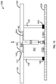
- FIG. 1B shows a cross-sectional view of the example sensing device
- FIG. 1C shows a partial cross-sectional view of the example sensing device
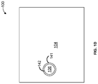
- FIG. 1D shows a top plan view of the example sensing device
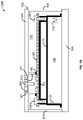
- FIG. 1E shows a partial cross-sectional view of the example sensing device
- FIG. 2A shows a perspective view of another example sensing device
- FIG. 2B shows a cross-section view of the other example sensing device
- FIG. 2C shows a partial cross-sectional view of the other example sensing device
- FIG. 2D shows a top plan view of the other example sensing device
- FIG. 2E shows a partial cross-sectional view of the example sensing device.
- the term “substantially constant” indicates that the constant relationship is not a strict relationship and does not exclude functionally similar variations therefrom.
- the term “substantially vertical” indicates that the vertical relationship of the element is not a strict limitation and does not exclude functionally similar variations therefrom.
- the term “substantially horizontal” indicates that the horizontal relationship of the element is not a strict limitation and does not exclude functionally similar variations therefrom.
- the term “substantially parallel” indicates that the parallel relationship is not a strict relationship and does not exclude functionally similar variations therefrom.
- the term “substantially level” indicates that the positional relationship is not a strict relationship and does not exclude functionally similar variations therefrom.
- blocks of the block diagrams support one or a combinations of devices for performing the specified functions.
- Certain devices include one or more sensors positioned within their housings to detect one or more environmental conditions.
- the housings of the devices need to have a sufficient level of ventilation.
- an air gap or other air flow path may be provided along a perimeter of or through a button or switch mechanism positioned along the exterior of the housing of the device to provide an airflow path into the chamber where the one or more sensors are located.
- the sensing device may include a housing that includes one or more walls.
- the housing may include a top wall, a bottom wall, and one or more side walls that together define a cavity within the housing.
- a circuit board may be positioned within the cavity and enclosed within the walls of the housing.
- An activation switch and one or more sensors may be operably coupled to the circuit board.
- at least one of the sensors may be an environmental sensor configured to detect an environmental condition, such as temperature, humidity, occupancy, barometric pressure, magnetic flux, light-level, vibration, or another environmental condition.
- One or more chamber walls may extend between the circuit board and the inner surface of the housing to surround the activation switch, the one or more sensors, and a portion of the circuit board to define a chamber within the cavity of the housing that seals off the portion of the circuit board from another portion of the circuit board.
- the one or more chamber walls may have a first end that abuts, is coupled to, or is integrally formed with one of the walls of the housing and a distal second end that abuts the circuit board.
- the chamber may be sealed off from the remainder of the housing cavity.
- the portion of the circuit board may be sealed off from the another portion of the circuit board by the one or more chamber walls.
- one or both of the first end and the second end of each of the one or more chamber side walls may include a non-conductive, flexible material, such as silicone.
- the one or more chamber walls may only enclose a small portion of the circuit board and cavity of the housing.
- An activation member such as a button or rotatory switch may be operably coupled to the housing and/or the circuit board and may extend through an opening in the housing and into the chamber within the housing.
- An air flow pathway such as an air gap or one or more apertures, may be provided between an outer edge of the activation member and an opening in the housing or through the activation member to provide an air flow pathway that defines a fluid communication channel from an exterior of the housing to the chamber, the portion of the circuit board, and/or the one or more sensors in the chamber.
- FIGS. 1A-E show various views of an example sensing device 100 that may be configured to sense environmental condition data, such as temperature data, humidity data, occupancy data, barometric pressure data, magnetic flux data, light-level data, vibration data, etc., and send that data to a user device and/or a computing device.
- the sensing device 100 may be one or more of a temperature sensor, a humidity sensor, an occupancy sensor, a photosensor, a barometric pressure sensor, a magnetic flux sensor, a vibration sensor, or any other type of sensor.
- the sensing device 100 may be configured to be mounted, either fixedly or removably, to a portion of a building, such as a wall, ceiling, or floor, either directly or indirectly with the use of additional components.
- the sensing device 100 may include a housing 102 .
- the housing 102 may be constructed of one or more pieces. For example multiple pieces of the housing 102 may be coupled together using coupling devices, such as screws, nails, rivets, adhesive, pins and apertures, or the like.
- the housing 102 may be made of metal, plastic, wood, or any combination thereof.
- the housing 102 may have any 3-dimensional shape.
- the housing 102 may be generally shaped as any one or more of a rectangular cuboid, cube, sphere, cylinder, triangular prism, or the like.
- the housing 102 may include one or more walls depending on the shape of the housing 102 and the desired function of the device 100 .
- the housing 102 may include a top wall 104 .
- the top wall 104 may include an outer facing surface and an inner facing surface.
- the top wall 104 may have any shape and surface.
- the shape of the top wall 104 may be rectangular, oval, circular, triangular or any other geometric or non-geometric shape.
- the outer surface of the top wall 104 may be planar, curved, and/or may include surface texturing.
- the housing 102 may also include a bottom wall 106 .
- the bottom wall 106 may include an outer facing surface and an inner facing surface.
- the bottom wall 106 may have any shape and surface.
- the shape of the bottom wall 106 may be rectangular, oval, circular, triangular or any other geometric or non-geometric shape.
- the outer surface of the bottom wall 106 may be planar, curved, and/or may include surface texturing.
- the housing 102 may also include one or more side walls.
- the one or more side walls may extend from the bottom wall 106 to the top wall 104 or from the bottom 106 or top 104 wall to an intermediate wall.
- the housing 102 may include a first side wall 107 that may have a first end coupled to the bottom wall 106 and a distal second end coupled to the top wall 104 .
- the first side wall 107 may be positioned along a first side of the housing 102 .
- the first side wall 107 may have any shape and surface.
- the shape of the first side wall 107 may be rectangular, oval, circular, triangular or any other geometric or non-geometric shape.
- the outer surface of the first side wall 107 may be planar, curved, and/or may include surface texturing.
- the housing 102 may include a second side wall 108 that may have a first end coupled to the bottom wall 106 and a distal second end coupled to the top wall 104 .
- the second side wall 108 may be positioned along a second side of the housing 102 .
- the second side wall 108 may have any shape and surface.
- the shape of the second side wall 108 may be rectangular, oval, circular, triangular or any other geometric or non-geometric shape.
- the outer surface of the second side wall 108 may be planar, curved, and/or may include surface texturing.
- the housing 102 may include a third side wall 109 that may have a first end coupled to the bottom wall 106 and a distal second end coupled to the top wall 104 .
- the third side wall 109 may be positioned along a third side of the housing 102 .
- the third side wall 109 may have any shape and surface.
- the shape of the third side wall 109 may be rectangular, oval, circular, triangular or any other geometric or non-geometric shape.
- the outer surface of the third side wall 109 may be planar, curved, and/or may include surface texturing.
- the housing 102 may include a fourth side wall 110 that may have a first end coupled to the bottom wall 106 and a distal second end coupled to the top wall 104 .
- the fourth side wall 110 may be positioned along a fourth side of the housing 102 .
- the fourth side wall 110 may have any shape and surface.
- the shape of the fourth side wall 110 may be rectangular, oval, circular, triangular or any other geometric or non-geometric shape.
- the outer surface of the fourth side wall 110 may be planar, curved, and/or may include surface texturing.
- the first side wall 107 may extend from the fourth side wall 110 to the second side wall 108 .
- the second side wall 108 may extend from the first side wall 107 to the third side wall 109 .
- the third side wall 109 may extend from the second side wall 108 to the fourth side wall 110 .
- the fourth side wall 110 may extend from the third side wall 109 to the first side wall 107 .
- the one or more top walls 104 , bottom walls 106 and side walls 107 - 110 may define a cavity 112 within the housing 102 .
- the cavity 112 may be an open space within the housing 102 that is configured to receive one or more components of the sensing device 100 .
- the sensing device 100 may also include an activation member 136 .
- the activation member 136 may be a manually adjustable device for turning on, turning off, or changing an operational status of the sensing device 100 .
- a user may apply a force to the activation member 136 to cause the sensing device 100 to be turned on, turn off, or to change an operational status of the sensing device 100 .
- the activation member 136 may be any one or more of a push-button switch, a rotary switch, a rocker switch, a slide switch, a toggle switch, a hall-effect sensor or reed switch with a magnet (not shown) on the opposing end of the shaft 140 , or any other type of switch known to those of ordinary skill in the art.
- the activation member 136 may be a push-button switch.
- the activation member 136 may include a head member 138 and a shaft 140 that has a first end coupled to the head member 138 and a distal free end that extends from one side of the head member 138 .
- the activation member 136 may be movable along the longitudinal axis Y with respect to the housing.
- the activation member 136 may also include a biasing member (not shown), such as a spring, that biases the activation member 136 in the direction A.
- the activation member 136 may be operably coupled to the housing 102 , the mounting platform 114 and/or the circuit board 124 .
- the activation member 136 may extend through an aperture in one of the walls 104 - 110 of the housing 102 and into the cavity 112 of the housing 102 .
- the top wall 104 , bottom wall 106 , first side wall 107 , second side wall 108 , third side wall 109 , or fourth side wall 110 may include a switch aperture 141 .
- the top wall may include the switch aperture 141 .
- the switch aperture 141 may have any shape, such as round, rectangular, triangular, oval, or any other geometric and non-geometric shape.
- the switch aperture 141 may have a perimeter having a perimeter distance that defines the opening through the top wall 104 .
- the head member 138 of the activation member 136 may have any shape, such as round, rectangular, triangular, oval, or any other geometric or non-geometric shape.
- the head member 138 can have a shape that corresponds with the shape of the switch aperture 141 .
- both the switch aperture 141 and the head member 138 may be circular, may be rectangular, may be triangular, may be oval, or may be any other corresponding shape.
- the sensing device 100 may include a mounting platform 114 .
- the mounting platform 114 may be a battery tray.
- the mounting platform may be positioned within the cavity 112 of the housing 102 .
- the mounting platform 114 may be coupled to one or more of the walls 104 - 110 of the housing 102 via one or more coupling devices, such as screws, rivets, pins, nails, adhesive, or the like.
- the mounting platform 114 may include one or more vertical or substantially vertical side walls and one or more horizontal or substantially horizontal mounting walls for receiving one or more components.
- the mounting platform may include one or more side walls and at least one mounting wall that may define a battery cavity 116 .
- the battery cavity 116 may be sized and shaped to receive and removably couple a battery (not shown) to the mounting platform 114 .
- the battery cavity 116 may include a battery contact 118 along a first end of the battery cavity 116 and a battery contact 120 along a distal second end of the battery cavity 116 .
- the battery contact 118 may be a spring contact and the battery contact 120 may be a tab contact. In other examples, the spring contact and the tab contact may be reversed.
- the battery contact 118 may be configured to abut a first end of a battery and the battery contact 120 may be configured to abut a distal second end of a battery.
- the battery may be configured to provide electrical power to a circuit board 124 positioned within the cavity 112 of the housing 102 .
- the battery may be removably inserted into the battery cavity 116 and be electrically coupled to the circuit board 124 via the contacts 118 , 120 or the battery may be hard wired and/or soldered to and electrically coupled to the circuit board 124 to provide electrical power to the circuit board 124 .
- the battery can be any type of battery, such as an alkaline battery, a lithium ion battery, a nickel cadmium battery, a button cell battery, or the like.
- the sensing device 100 may include a circuit board 124 .
- the circuit board 124 may be positioned within the cavity 112 of the housing 102 .
- the circuit board 124 may be coupled to the mounting platform 114 or the housing 102 .
- the circuit board 124 may be coupled to a mounting surface 122 of the mounting platform 114 .
- one or more coupling devices 126 A-B may be used to couple the circuit board 124 to the mounting surface 122 .
- the one or more coupling devices 126 A-B may be any one or more of a screw, a rivet, a pin, adhesive, or the like.
- each of the one or more coupling devices 126 A-B may be a screw that extends through an aperture in the circuit board 124 and the mounting surface 122 to threadably couple the circuit board 124 to the mounting platform 114 .
- the circuit board 124 may be any type of circuit board, such as a printed circuit board (PCB), a strip board, or a bread board.
- the PCB may be any type of PCB, such as a single layer PCB, a double layer PCB, a multi-layer PCB, a high density interconnect PCB, or a high frequency PCB.
- the circuit board 124 may have a top surface and an opposing bottom surface. The bottom surface of the circuit board 124 may abut a top surface of the mounting surface 122 and the top surface of the circuit board 124 may face an inner surface of one of the walls 104 - 110 of the housing 102 . For example, the top surface of the circuit board 124 may face an inner surface of the top wall 104 .
- the circuit board 124 may be electrically coupled to a battery in the battery cavity 116 or to another power source.
- the circuit board 124 may include any number of components positioned on and electrically coupled to the circuit board 124 .
- an activation switch 128 may be positioned along a surface of the circuit board 124 .
- the activation switch 128 may be positioned along the top surface of the circuit board 124 and may be electrically coupled to the circuit board 124 .
- the activation switch 128 may be positioned below and/or otherwise aligned with the shaft 140 of the activation member 136 .
- the activation member 136 may be configured to operably engage at least a portion of the activation switch 128 .
- a user may apply a manual force on the head member 138 of the activation member 136 in the direction B to move the activation member 136 in the direction B until the free end of the shaft 140 contacts a portion of the activation switch 128 and activates the activation switch 128 .
- the free end of the shaft 140 may depress a button on the activation switch 128 .
- the biasing member may move the activation member 136 in the direction A.
- One or more sensors 130 , 132 may be positioned along a surface of the circuit board 124 .
- the one or more sensors 130 , 132 may be positioned along the top surface of the circuit board 124 and may be electrically coupled to the circuit board 124 .
- the one or more sensors 130 , 132 may be mounted in another portion of the cavity 112 of the housing 102 and communicably coupled to the circuit board 124 .
- Each of the one or more sensors 130 , 132 may be configured to sense one or more environmental conditions, such as temperature, humidity, occupancy, barometric pressure, magnetic flux, light-level, vibration, and the like.
- the sensor 130 may be configured to sense ambient temperature and the sensor 132 may be configured to sense ambient humidity.
- the senor 130 may be configured to sense ambient temperature and ambient humidity and the sensor 132 may be configured to sense another environmental condition or may be eliminated altogether.
- the one or more sensors 130 , 132 may be positioned adjacent to the activation switch 128 on the circuit board 124 . In another example, the one or more sensors 130 , 132 may be positioned in another portion of the housing away from the activation switch 128
- the sensing device 100 may include a chamber.
- the chamber may include one or more chamber side walls 148 .
- the one or more chamber side walls 148 may have a first end coupled to the housing 102 .
- the one or more chamber side walls 148 may have a first end coupled to an inner surface of the wall 104 - 110 that includes the switch aperture 141 .
- the one or more chamber side walls 148 may have a first end coupled to an inner surface of the top wall 104 .
- the first end of the one or more chamber side walls 148 may be positioned adjacent to the switch aperture 141 .
- the one or more chamber side walls 148 may extend from the inner surface of the top wall 104 towards the circuit board 124 .
- the second end of the one or more chamber side walls 148 may extend to the circuit board 124 .
- the second end of the one or more chamber side walls 148 may contact a top or bottom surface of the circuit board 124 .
- the second end of the one or more chamber side walls 148 may include a gasket 146 for contacting the circuit board.
- each of the one or more chamber side walls 148 may be constructed of more than one material.
- a first material may make up the first end of the one or more chamber side walls 148 that extends towards the circuit board 124 and a second material, the gasket 146 , that makes up the second end of the one or more chamber side walls 148 and that contacts the circuit board 124 .
- Both the first material and the second material that make up each of the one or more chamber side walls 148 may be a non-conductive material, and may be constructed of the same or different materials (e.g., non-conductive materials such as rubber, synthetic rubber, plastic, ceramic, or silicone).
- the first material may be plastic and the second material, the gasket 146 , may be silicone.
- the one or more chamber side walls 148 may be coupled to one another to define any connected 3-dimensional shape, such as a cylinder, an ellipsoid, rectangular cuboid, cube, triangular prism, or any other shape.
- the sensing device 100 may include one chamber side wall 148 in the shape of a cylinder.
- the one or more chamber side walls 148 may surround a portion (e.g., less than 50%, less than 30%, less than 20%, less than 10%, less than 5%) of the surface of the circuit board 124 and may seal off the portion of the circuit board from another portion of the circuit board.
- the one or more chamber side walls 148 may surround the activation switch 128 and the one or more sensors 130 , 132 .
- the one or more chamber side walls 148 may define a chamber 152 that seals a portion of the circuit board 124 (e.g., less than 50%, less than 30%, less than 20%, less than 10%, less than 5%) from a remaining portion of the circuit board 124 and extends from the circuit board to the inner surface of the top wall 104 .
- the chamber 152 may include one or more of the activation switch 128 and the one or more sensors 130 , 132 .
- the portion of the circuit board 124 within the chamber 152 may be smaller than the portion of the circuit board 124 outside of the chamber 152 .
- the portion of the circuit board 124 within the chamber 152 may be anywhere between about 1 percent to about 40 percent of the surface area of the top surface of the circuit board 124 .
- the chamber 152 may be generally aligned with the activation member 136 such that the shaft 140 extends into the chamber 152 and the air gaps 142 are in fluid communication with the chamber 152 .
- the chamber 152 may be sealed off from the remaining portion of the housing 102 by the one or more chamber side walls 148 and the portion of the circuit board 124 within the chamber 152 .
- the seal may be air tight and/or water tight.
- the one or more chamber side walls 148 may extend from the inner surface of the top wall 104 towards a secondary bottom wall.
- the second end of the one or more chamber side walls 148 may extend to the secondary bottom wall to create a secondary chamber within the cavity 112 .
- the second end of the one or more chamber side walls 148 may contact, be coupled to or integrally formed with the secondary bottom wall.
- the one or more chamber side walls 148 may be coupled to one another to define any connected 3-dimensional shape, such as a cylinder, an ellipsoid, rectangular cuboid, cube, triangular prism, or any other shape.
- the sensing device 100 may include one chamber side wall 148 in the shape of a cylinder.
- the one or more chamber side walls 148 may surround the activation switch 128 and the one or more sensors 130 , 132 .
- the one or more sensors 130 , 132 may be mounted anywhere within the housing and communicably coupled to the circuit board 124 .
- the secondary chamber may include one or more of the activation switch 128 and the one or more sensors 130 , 132 .
- the secondary chamber may be generally aligned with the activation member 136 such that the shaft 140 extends into the secondary chamber and the air gaps 142 are in fluid communication with the secondary chamber.
- the secondary chamber may be sealed off from the remaining portion of the housing 102 by the one or more chamber side walls 148 and the secondary bottom wall.
- the seal may be air tight and/or water tight.
- the air gap 142 may be sufficient to allow air to flow between the outer perimeter of the head member 138 and the perimeter of the switch aperture 141 from an area outside of the housing 102 and into the chamber 152 .
- the air gap 142 may not be in fluid communication with portions of the cavity 112 of the housing 102 outside of the chamber 152 .
- the air, flowing into the chamber 152 through the air gap 142 may come into contact with the one or more sensors 130 , 132 .
- the air flowing through the air gap 142 may be trapped in the chamber 152 and may not disperse into other portions of the cavity 112 in the housing 102 .
- the chamber 152 having a substantially smaller volume than the entire cavity 112 of the housing 102 , may be able to more quickly equate to certain environmental conditions outside of the housing 102 , such as temperature, humidity, and light level, such that the one or more sensors 130 , 132 may provide more accurate readings of the environmental conditions outside of the housing 102 .
- the sensing device 100 may include a membrane or gasket 144 .
- the membrane/gasket 144 may be positioned along or adjacent the switch aperture 141 .
- the membrane/gasket 144 may be positioned along an exterior surface of the housing 102 (e.g., along the exterior surface of the top wall 104 ) and coupled to the exterior surface of the housing and/or the activation member 136 to cover the one or more air gaps 142 .
- the membrane gasket 144 may be sandwiched between two pieces of the head member 138 and extend therefrom to cover the one or more air gaps 142 .
- the membrane/gasket 144 may extend from the head member 138 to the perimeter of the switch aperture 141 .
- the membrane/gasket 144 may be configured to allow air and/or water vapor to pass through the membrane/gasket 144 via the air gap 142 and into the chamber 152 .
- the membrane/gasket 144 may be configured to prevent liquid water from passing through the membrane/gasket 144 .
- the membrane/gasket 144 may be constructed of any porous material.
- the membrane/gasket 144 may be constructed of a porous material that may repel liquid water while allowing air and water vapor to pass through the membrane/gasket 144 and into the chamber 152 .
- the membrane/gasket 144 may be constructed of stretched polytetrafluoroethylene (PTFE), expanded PTFE (ePTFE) Gore-Tex, Teflon or neoprene.
- the sensing device 100 may include a transmitter or transceiver 162 .
- the transmitter or transceiver 162 may be positioned along a surface of the circuit board 124 .
- the transmitter or transceiver 162 may be positioned along the top surface of the circuit board 124 outside of the chamber 152 and may be electrically coupled to the circuit board 124 .
- the transmitter or transceiver 162 may be communicably coupled to the one or more sensors 130 , 132 .
- the transmitter or transceiver may be configured to transmit environmental data received from the one or more sensors 130 , 132 to a wireless device or another computer.
- FIGS. 2A-E show various views of an example sensing device 200 that may be configured to sense environmental condition data, such as temperature data, humidity data, occupancy data, barometric pressure data, magnetic flux data, light-level data, vibration data, etc., and send that data to a user device and/or a computing device.
- the sensing device 200 may be one or more of a temperature sensor, a humidity sensor, an occupancy sensor, a photosensor, a barometric pressure sensor, a magnetic flux sensor, a vibration sensor, or any other type of sensor.
- the sensing device 200 may be configured to be mounted, either fixedly or removably, to a portion of a building, such as a wall, ceiling, or floor, either directly or indirectly with the use of additional components.
- the sensing device 200 may include a housing 102 .
- the housing 102 may be constructed of one or more pieces. For example multiple pieces of the housing 102 may be coupled together using coupling devices, such as screws, nails, rivets, adhesive, pins and apertures, or the like.
- the housing 102 may be made of metal, plastic, wood, or any combination thereof.
- the housing 102 may have any 3-dimensional shape.
- the housing 102 may be generally shaped as any one or more of a rectangular cuboid, cube, sphere, cylinder, triangular prism, or the like.
- the housing 102 may include one or more walls depending on the shape of the housing 102 and the desired function of the device 200 .
- the housing 102 may include a top wall 104 .
- the top wall 104 may include an outer facing surface and an inner facing surface.
- the top wall 104 may have any shape and surface.
- the shape of the top wall 104 may be rectangular, oval, circular, triangular or any other geometric or non-geometric shape.
- the outer surface of the top wall 104 may be planar, curved, and/or may include surface texturing.
- the housing 102 may also include a bottom wall 106 .
- the bottom wall 106 may include an outer facing surface and an inner facing surface.
- the bottom wall 106 may have any shape and surface.
- the shape of the bottom wall 106 may be rectangular, oval, circular, triangular or any other geometric or non-geometric shape.
- the outer surface of the bottom wall 106 may be planar, curved, and/or may include surface texturing.
- the housing 102 may also include one or more side walls.
- the one or more side walls may extend from the bottom wall 106 to the top wall 104 or from the bottom 106 or top 104 wall to an intermediate wall.
- the housing 102 may include a first side wall 107 that may have a first end coupled to the bottom wall 106 and a distal second end coupled to the top wall 104 .
- the first side wall 107 may be positioned along a first side of the housing 102 .
- the first side wall 107 may have any shape and surface.
- the shape of the first side wall 107 may be rectangular, oval, circular, triangular or any other geometric or non-geometric shape.
- the outer surface of the first side wall 107 may be planar, curved, and/or may include surface texturing.
- the housing 102 may include a second side wall 108 that may have a first end coupled to the bottom wall 106 and a distal second end coupled to the top wall 104 .
- the second side wall 108 may be positioned along a second side of the housing 102 .
- the second side wall 108 may have any shape and surface.
- the shape of the second side wall 108 may be rectangular, oval, circular, triangular or any other geometric or non-geometric shape.
- the outer surface of the second side wall 108 may be planar, curved, and/or may include surface texturing.
- the housing 102 may include a third side wall 109 that may have a first end coupled to the bottom wall 106 and a distal second end coupled to the top wall 104 .
- the third side wall 109 may be positioned along a third side of the housing 102 .
- the third side wall 109 may have any shape and surface.
- the shape of the third side wall 109 may be rectangular, oval, circular, triangular or any other geometric or non-geometric shape.
- the outer surface of the third side wall 109 may be planar, curved, and/or may include surface texturing.
- the housing 102 may include a fourth side wall 110 that may have a first end coupled to the bottom wall 106 and a distal second end coupled to the top wall 104 .
- the fourth side wall 110 may be positioned along a fourth side of the housing 102 .
- the fourth side wall 110 may have any shape and surface.
- the shape of the fourth side wall 110 may be rectangular, oval, circular, triangular or any other geometric or non-geometric shape.
- the outer surface of the fourth side wall 110 may be planar, curved, and/or may include surface texturing.
- the first side wall 107 may extend from the fourth side wall 110 to the second side wall 108 .
- the second side wall 108 may extend from the first side wall 107 to the third side wall 109 .
- the third side wall 109 may extend from the second side wall 108 to the fourth side wall 110 .
- the fourth side wall 110 may extend from the third side wall 109 to the first side wall 107 .
- the one or more top walls 104 , bottom walls 106 and side walls 107 - 110 may define a cavity 112 within the housing 102 .
- the cavity 112 may be an open space within the housing 102 that is configured to receive one or more components of the sensing device 200 .
- the sensing device 200 may include an activation member 202 .
- the activation member 202 may be a manually adjustable device for turning on, turning off, or changing an operational status of the sensing device 200 .
- a user may apply a force to the activation member 202 to cause the sensing device 200 to be turned on, turn off, or to change an operational status of the sensing device 200 .
- the activation member 202 may be any one or more of a push-button switch, a rotary switch, a rocker switch, a slide switch, a toggle switch, a hall-effect sensor or reed switch with a magnet (not shown) on the opposing end of the shaft 208 , or any other type of switch known to those of ordinary skill in the art.
- the activation member 202 may be a push-button switch.
- the activation member 202 may include a head member 204 and a shaft 208 that has a first end coupled to the head member 204 and a distal free end that extends from one side of the head member 204 .
- the activation member 202 may be movable along the longitudinal axis Y with respect to the housing 102 .
- the activation member 202 may also include a biasing member (not shown), such as a spring, that biases the activation member 202 in the direction A.
- the activation member 202 may be operably coupled to the housing 102 , the mounting platform 114 and/or the circuit board 124 .
- the activation member 202 may extend through an aperture in one of the walls 104 - 110 of the housing 102 and into the cavity 112 of the housing 102 .
- the top wall 104 , bottom wall 106 , first side wall 107 , second side wall 108 , third side wall 109 , or fourth side wall 110 may include a switch aperture 141 .
- the top wall 104 may include the switch aperture 141 .
- the switch aperture 141 may have any shape, such as round, rectangular, triangular, oval, or any other geometric and non-geometric shape.
- the switch aperture 141 may have a perimeter having a perimeter distance that defines the opening through the top wall 104 .
- the head member 204 of the activation member 202 may have any shape, such as round, rectangular, triangular, oval, or any other geometric or non-geometric shape.
- the head member 204 can have a shape that corresponds with the shape of the switch aperture 141 .
- both the switch aperture 141 and the head member 204 may be circular, may be rectangular, may be triangular, may be oval, or may be any other corresponding shape.
- the head member 204 may have an outer perimeter with a perimeter distance that is equal to or slightly less than the perimeter distance of the switch aperture 141 .
- the head member 204 may be capable of being inserted into and through the switch aperture 141 with little to no space between the outer perimeter of the head member 204 and the perimeter of the switch aperture 141 .
- the top surface of the head member 204 in a resting position, may be level or substantially level with the outer surface of the top wall 104 .
- the top surface of the head member 204 may extend above or be recessed below the outer surface of the top wall 104 .
- the head member 204 may include one or more apertures 206 A-F that extend through head member 204 to provide one or more air pathways through the head member 204 . While FIGS. 2A-D show six apertures 206 A-F extending through the head member 204 this is for example purposes only as the number of apertures 206 A-F that extend through the head member 204 may be one or more. Each aperture 206 A-F may have the same diameter or one or more of the apertures 206 A-F may have a different diameter.
- the one or more apertures 206 A-F may be positioned along the head member 204 in any manner. For example, the one or more apertures 206 A-F may be equally-spaced along the surface of the head member 204 .
- Each of the one or more air pathways may be configured to allow ambient air from outside of the housing 102 to flow through the one or more air pathways and into the chamber 152 .
- the sensing device 200 may include a mounting platform 114 .
- the mounting platform 114 may be a battery tray.
- the mounting platform 114 may be positioned within the cavity 112 of the housing 102 .
- the mounting platform 114 may be coupled to one or more of the walls 104 - 110 of the housing 102 via one or more coupling devices, such as screws, rivets, pins, nails, adhesive, or the like.
- the mounting platform 114 may include one or more vertical or substantially vertical side walls and one or more horizontal or substantially horizontal mounting walls for receiving one or more components.
- the mounting platform 114 may include one or more side walls and at least one mounting wall that may define a battery cavity 116 .
- the battery cavity 116 may be sized and shaped to receive and removably couple a battery (not shown) to the mounting platform 114 .
- the battery cavity 116 may include a battery contact 118 along a first end of the battery cavity 116 and a battery contact 120 along a distal second end of the battery cavity 116 .
- the battery contact 118 may be a spring contact and the battery contact 120 may be a tab contact. In other examples, the spring contact and the tab contact may be reversed.
- the battery contact 118 may be configured to abut a first end of a battery and the battery contact 120 may be configured to abut a distal second end of a battery.
- the battery may be configured to provide electrical power to a circuit board 124 positioned within the cavity 112 of the housing 102 .
- the battery may be removably inserted into the battery cavity 116 and may be electrically coupled to the circuit board 124 via the contacts 118 , 120 , or the battery may be hard wired and/or soldered to and electrically coupled to the circuit board 124 to provide electrical power to the circuit board 124 .
- the battery can be any type of battery, such as an alkaline battery, a lithium ion battery, a nickel cadmium battery, a button cell battery, or the like.
- the sensing device 200 may include a circuit board 124 .
- the circuit board 124 may be positioned within the cavity 112 of the housing 102 .
- the circuit board 124 may be coupled to the mounting platform 114 and/or the housing 102 .
- the circuit board 124 may be coupled to a mounting surface 122 of the mounting platform 114 .
- one or more coupling devices 126 A-B may be used to couple the circuit board 124 to the mounting surface 122 .
- the one or more coupling devices 126 A-B may be any one or more of a screw, a rivet, a pin, adhesive, or the like.
- each of the one or more coupling devices 126 A-B may be a screw that extends through an aperture in the circuit board 124 and the mounting surface 122 to threadably couple the circuit board 124 to the mounting platform 114 .
- the circuit board 124 may be any type of circuit board, such as a printed circuit board (PCB), a strip board, or a bread board.
- the PCB may be any type of PCB, such as a single layer PCB, a double layer PCB, a multi-layer PCB, a high density interconnect PCB, or a high frequency PCB.
- the circuit board 124 may have a top surface and an opposing bottom surface. The bottom surface of the circuit board 124 may abut a top surface of the mounting surface 122 and the top surface of the circuit board 124 may face an inner surface of one of the walls 104 - 110 of the housing 102 . For example, the top surface of the circuit board 124 may face an inner surface of the top wall 104 .
- the circuit board 124 may be electrically coupled to a battery in the battery cavity 116 or to another power source.
- the circuit board 124 may include any number of components positioned on and electrically coupled to the circuit board 124 .
- an activation switch 128 may be positioned along a surface of the circuit board 124 .
- the activation switch 128 may be positioned along the top surface of the circuit board 124 and may be electrically coupled to the circuit board 124 .
- the activation switch 128 may be positioned below and/or otherwise aligned with the shaft 208 of the activation member 202 .
- the activation member 202 may be configured to operably engage at least a portion of the activation switch 128 .
- a user may apply a manual force on the head member 204 of the activation member 202 in the direction B to move the activation member 202 in the direction B until the free end of the shaft 208 contacts a portion of the activation switch 128 and activates the activation switch 128 .
- the free end of the shaft 208 may depress a button on the activation switch 128 .
- the biasing member may move the activation member 202 in the direction A.
- One or more sensors 130 , 132 may be positioned along a surface of the circuit board 124 .
- the one or more sensors 130 , 132 may be positioned along the top surface of the circuit board 124 and may be electrically coupled to the circuit board 124 .
- the one or more sensors 130 , 132 may be mounted in another portion of the cavity 112 of the housing 102 and communicably coupled to the circuit board 124 .
- Each of the one or more sensors 130 , 132 may be configured to sense one or more environmental conditions, such as temperature, humidity, occupancy, barometric pressure, magnetic flux, light-level, vibration, and the like.
- the sensor 130 may be configured to sense ambient temperature and the sensor 132 may be configured to sense ambient humidity.
- the senor 130 may be configured to sense ambient temperature and ambient humidity and the sensor 132 may be configured to sense another environmental condition or may be eliminated altogether.
- the one or more sensors 130 , 132 may be positioned adjacent to the activation switch 128 on the circuit board 124 . In another example, the one or more sensors 130 , 132 may be positioned in another portion of the housing away from the activation switch 128
- the sensing device 200 may include one or more chamber side walls 148 .
- the one or more chamber side walls 148 may have a first end coupled to the housing 102 .
- the one or more chamber side walls 148 may have a first end coupled to an inner surface of the wall 104 - 110 that includes the switch aperture 141 .
- the one or more chamber side walls 148 may have a first end coupled to an inner surface of the top wall 104 .
- the first end of the one or more chamber side walls 148 may be positioned adjacent to the switch aperture 141 .
- the one or more chamber side walls 148 may extend from the inner surface of the top wall 104 towards the circuit board 124 .
- the second end of the one or more chamber side walls 148 may extend to the circuit board 124 .
- the second end of the one or more chamber side walls 148 may contact the top or bottom surface of the circuit board 124 .
- the second end of the one or more chamber side walls 148 may include a gasket 146 for contacting the surface of the circuit board.
- each of the one or more chamber side walls 148 may be constructed of more than one material.
- a first material may make up the first end of the one or more chamber side walls 148 that extends towards the circuit board 124 and a second material, the gasket 146 , that makes up the second end of the one or more chamber side walls 148 and that contacts the circuit board 124 .
- Both the first material and the second material that make up each of the one or more chamber side walls 148 may be a non-conductive material, and may be constructed of the same or different materials (e.g., non-conductive materials such as rubber, synthetic rubber, plastic, ceramic, or silicone).
- the first material may be plastic and the second material, the gasket 146 , may be silicone.
- the one or more chamber side walls 148 may be coupled to one another to define any connected 3-dimensional shape, such as a cylinder, an ellipsoid, rectangular cuboid, cube, triangular prism, or any other shape.
- the sensing device 200 may include one chamber side wall 148 in the shape of a cylinder.
- the one or more chamber side walls 148 may surround a portion (e.g., less than 50%, less than 30%, less than 20%, less than 10%, less than 5%) of the surface of the circuit board 124 .
- the one or more chamber side walls 148 may surround the activation switch 128 and the one or more sensors 130 , 132 .
- the one or more chamber side walls 148 may define a chamber 152 that seals a portion of the circuit board 124 (e.g., less than 50%, less than 30%, less than 20%, less than 10%, less than 5%) from a remaining portion of the circuit board 124 and extends from the circuit board to the inner surface of the top wall 104 .
- the chamber 152 may include one or more of the activation switch 128 and the one or more sensors 130 , 132 .
- the portion of the circuit board 124 within the chamber 152 may be smaller than the portion of the circuit board 124 outside of the chamber 152 .
- the portion of the circuit board 124 within the chamber 152 may be anywhere between 1-40 percent of the surface area of the top surface of the circuit board 124 .
- the chamber 152 may be generally aligned with the activation member 202 such that the shaft 208 extends into the chamber 152 and a fluid communication channel is defined from an exterior of the housing 102 , through the one or more air pathways 206 A-F in the head member 204 and into the chamber 152 to the portion of the circuit board and/or the one or more sensors 130 , 132 .
- the chamber 152 may be sealed off from the remaining portion of the housing 102 by the one or more chamber side walls 148 and the portion of the circuit board 124 within the chamber 152 .
- the seal may be air tight and/or water tight.
- the one or more chamber side walls 148 may extend from the inner surface of the top wall 104 towards a secondary bottom wall.
- the second end of the one or more chamber side walls 148 may extend to the secondary bottom wall to create a secondary chamber within the cavity 112 .
- the second end of the one or more chamber side walls 148 may contact, be coupled to or integrally formed with the secondary bottom wall.
- the one or more chamber side walls 148 may be coupled to one another to define any connected 3-dimensional shape, such as a cylinder, an ellipsoid, rectangular cuboid, cube, triangular prism, or any other shape.
- the sensing device 100 may include one chamber side wall 148 in the shape of a cylinder.
- the one or more chamber side walls 148 may surround the activation switch 128 and the one or more sensors 130 , 132 .
- the one or more sensors 130 , 132 may be mounted anywhere within the housing and communicably coupled to the circuit board 124 .
- the secondary chamber may include one or more of the activation switch 128 and the one or more sensors 130 , 132 .
- the secondary chamber may be generally aligned with the activation member 202 such that the shaft 208 extends into the secondary chamber and the one or more air pathways 206 A-F defining a fluid communication channel in fluid communication with the secondary chamber.
- the secondary chamber may be sealed off from the remaining portion of the housing 102 by the one or more chamber side walls 148 and the secondary bottom wall and may seal off a portion of the circuit board from another portion of the circuit board.
- the seal may be air tight and/or water tight.
- the one or more air pathways 206 A-F through the head member 204 may be sufficiently sized to allow air to flow through the one or more air pathways 206 A-F along a fluid communication channel from an area outside of the housing 102 and into the chamber 152 to and/or towards the portion of the circuit board and/or one or more sensors 130 , 132 .
- the one or more air pathways 206 A-F through the head member 204 may not be in fluid communication with or define fluid communication channels to portions of the cavity 112 of the housing 102 outside of the chamber 152 .
- the air, flowing into the chamber 152 through the one or more air pathways 206 A-F through the head member 204 may come into contact with the one or more sensors 130 , 132 .
- the air flowing through the one or more air pathways 206 A-F through the head member 204 may be trapped in the chamber 152 and may not disperse into other portions of the cavity 112 in the housing 102 .
- the chamber 152 having a substantially smaller volume than the entire cavity 112 of the housing 102 , may be able to more quickly equate to certain environmental conditions outside of the housing 102 , such as temperature, humidity, and light level, such that the one or more sensors 130 , 132 may provide more accurate readings of the environmental conditions outside of the housing 102 .
- the sensing device 200 may include a membrane or gasket 144 .
- the membrane/gasket 144 may be positioned along or adjacent the switch aperture 141 .
- the membrane/gasket 144 may extend along a bottom surface of the head member 204 to cover the one or more air pathways 206 A-F through the head member 204 and extend to the perimeter of the switch aperture 141 .
- the membrane/gasket 144 may be positioned along an exterior surface of the housing 102 (e.g., along the exterior surface of the top wall 104 ) and coupled to the exterior surface of the housing and/or the activation member 202 to cover the one or more air pathways 206 A-F.
- the membrane gasket 144 may be sandwiched between two pieces of the head member 204 and extend therefrom to cover the one or more air pathways 206 A-F.
- the membrane/gasket 144 may be configured to allow air and/or water vapor to pass through the membrane/gasket 144 via the one or more air pathways 206 A-F through the head member 204 and into the chamber 152 .
- the membrane/gasket 144 may be configured to prevent liquid water from passing through the membrane/gasket 144 .
- the membrane/gasket 144 may be constructed of any porous material.
- the membrane/gasket 144 may be constructed of a porous material that may repel liquid water while allowing air and water vapor to pass through the membrane/gasket 144 and into the chamber 152 .
- the membrane/gasket 144 may be constructed of stretched polytetrafluoroethylene (PTFE), expanded PTFE (ePTFE), Gore-Tex, Teflon or neoprene.
- the sensing device 200 may include a transmitter or transceiver 162 .
- the transmitter or transceiver 162 may be positioned along a surface of the circuit board 124 .
- the transmitter or transceiver 162 may be positioned along the top surface of the circuit board 124 outside of the chamber 152 and may be electrically coupled to the circuit board 124 .
- the transmitter or transceiver 162 may be communicably coupled to the one or more sensors 130 , 132 .
- the transmitter or transceiver may be configured to transmit environmental data received from the one or more sensors 130 , 132 to a wireless device or another computer.
Landscapes
- Engineering & Computer Science (AREA)
- Microelectronics & Electronic Packaging (AREA)
- Physics & Mathematics (AREA)
- General Physics & Mathematics (AREA)
- Fire-Detection Mechanisms (AREA)
Abstract
Description
- Certain devices are designed with sensors to detect certain environmental conditions. Those conditions can include temperature, humidity, light level, motion, occupancy, vibration, etc. In order to protect the sensors, conventional devices position the sensors within a device housing. However, placing the sensors within the device housing can limit the sensors ability to sense ambient conditions outside of the housing or can provide incorrect data regarding the ambient conditions outside of the housing. Conventional devices have attempted to provide the sensors with better access to the ambient conditions by addition multiple openings in the housing. While the multiple openings can provide some access to ambient conditions, the access is limited and can require a significant amount of time for the ambient conditions to filter through the entire housing. Also, the multiple openings can make the housing and its components more susceptible to moisture intrusion.
- It is to be understood that both the following general description and the following detailed description are exemplary and explanatory only and are not restrictive. A device for sensing environmental conditions is described. The apparatus may include a housing. The housing may include one or more walls. For example, the housing may include a top wall, a bottom wall, and one or more side walls that together define a cavity within the housing. A circuit board may be positioned within the housing and enclosed within the walls of the housing.
- An activation switch and one or more sensors may be operably coupled to the circuit board. For example, at least one of the sensors may be an environmental sensor configured to detect, at the sensing device, an environmental condition, such as temperature, humidity, occupancy, barometric pressure, magnetic flux, light-level, vibration, or another environmental condition. One or more chamber walls may extend between the circuit board and the inner surface of the housing to surround the activation switch and the one or more sensors and define a chamber within the cavity of the housing that seals off a portion of the circuit board from another portion of the circuit board within the cavity. The one or more chamber walls may only enclose or seal off a small portion of the circuit board and cavity of the housing.
- An activation member, such as a button or rotatory switch may be operably coupled to the housing and/or the circuit board and may extend through an opening in one of the walls of the housing and into the chamber within the housing. An air flow pathway, such as an air gap or one or more apertures, may be provided between an outer edge of the activation member and an opening in one of the walls of the housing or through a head member of the activation member to provide an air flow pathway from an exterior of the housing to the one or more sensors in the chamber.
- This summary is not intended to identify critical or essential features of the disclosure, but merely to summarize certain features and variations thereof. Other details and features will be described in the sections that follow.
- The accompanying drawings, which are incorporated in and constitute a part of the present description serve to explain the principles of the apparatuses and systems described herein:
-
FIG. 1A shows a perspective view of an example sensing device; -
FIG. 1B shows a cross-sectional view of the example sensing device; -
FIG. 1C shows a partial cross-sectional view of the example sensing device; -
FIG. 1D shows a top plan view of the example sensing device; -
FIG. 1E shows a partial cross-sectional view of the example sensing device; -
FIG. 2A shows a perspective view of another example sensing device; -
FIG. 2B shows a cross-section view of the other example sensing device; -
FIG. 2C shows a partial cross-sectional view of the other example sensing device; -
FIG. 2D shows a top plan view of the other example sensing device; and -
FIG. 2E shows a partial cross-sectional view of the example sensing device. - As used in the specification and the appended claims, the singular forms “a,” “an,” and “the” include plural referents unless the context clearly dictates otherwise. Ranges may be expressed herein as from “about” one particular value, and/or to “about” another particular value. When such a range is expressed, another configuration includes from the one particular value and/or to the other particular value. When values are expressed as approximations, by use of the antecedent “about,” it will be understood that the particular value forms another configuration. It will be further understood that the endpoints of each of the ranges are significant both in relation to the other endpoint, and independently of the other endpoint.
- “Optional” or “optionally” means that the subsequently described element, feature, event, or circumstance may or may not be included or occur, and that the description includes cases where said element, feature, event, or circumstance is included or occurs and cases where it is not included or does not occur.
- Throughout the description and claims of this specification, the word “comprise” and variations of the word, such as “comprising” and “comprises,” means “including but not limited to,” and is not intended to exclude other components, integers or steps. “Exemplary” means “an example of” and is not intended to convey an indication of a preferred or ideal configuration. “Such as” is not used in a restrictive sense, but for explanatory purposes.
- Certain relationships between dimensions of the sensor device described herein and between features of the sensor device are described herein using the term “substantially.” As used herein, the terms “substantially” and “substantially equal” indicates that the equal relationship is not a strict relationship and does not exclude functionally similar variations therefrom. Unless context or the description indicates otherwise, the use of the term “substantially” or “substantially equal” in connection with two or more described dimensions or positions indicates that the equal relationship between the dimensions or positions includes variations that, using mathematical and industrial principles accepted in the art (e.g., rounding, measurement or other systematic errors, manufacturing tolerances, etc.), would not vary the least significant digit of the dimensions. As used herein, the term “substantially constant” indicates that the constant relationship is not a strict relationship and does not exclude functionally similar variations therefrom. As used herein, the term “substantially vertical” indicates that the vertical relationship of the element is not a strict limitation and does not exclude functionally similar variations therefrom. As used herein, the term “substantially horizontal” indicates that the horizontal relationship of the element is not a strict limitation and does not exclude functionally similar variations therefrom. As used herein, the term “substantially parallel” indicates that the parallel relationship is not a strict relationship and does not exclude functionally similar variations therefrom. As used herein the term “substantially level” indicates that the positional relationship is not a strict relationship and does not exclude functionally similar variations therefrom.
- It is understood that when combinations, subsets, interactions, groups, etc. of components are described that, while specific reference of each various individual and collective combinations and permutations of these may not be explicitly described, each is specifically contemplated and described herein. This applies to all parts of this application including, but not limited to, elements and features in described apparatuses and steps in described methods. Thus, if there are a variety of additional steps that may be performed or elements and features that may be included or substituted, it is understood that each of these additional steps may be performed or elements and features may be included or substituted with any specific configuration or combination of configurations of the described methods and apparatuses.
- Throughout this application reference is made to block diagrams. It will be understood that each block of the block diagrams, and combinations of blocks in the block diagrams, respectively, may be implemented in a number of different ways. Accordingly, blocks of the block diagrams support one or a combinations of devices for performing the specified functions.
- Certain devices include one or more sensors positioned within their housings to detect one or more environmental conditions. In order for the one or more sensors to achieve the most accurate readings of environmental conditions outside of the housing, such as temperature, humidity, or other environmental conditions, the housings of the devices need to have a sufficient level of ventilation. By creating a chamber within the housing that includes the one or more sensors and that is smaller than the overall volume of the cavity of the housing and by sealing that chamber off from the remaining part of the housing, a smaller space is created that requires less ventilation and will more quickly reach an equilibrium with the ambient environmental conditions outside of the housing. Instead of creating additional openings along the housing of the device, which could potentially affect the IP rating of the device, an air gap or other air flow path may be provided along a perimeter of or through a button or switch mechanism positioned along the exterior of the housing of the device to provide an airflow path into the chamber where the one or more sensors are located.
- Accordingly, a device for sensing environmental conditions is shown and described. The sensing device may include a housing that includes one or more walls. For example, the housing may include a top wall, a bottom wall, and one or more side walls that together define a cavity within the housing. A circuit board may be positioned within the cavity and enclosed within the walls of the housing.
- An activation switch and one or more sensors may be operably coupled to the circuit board. For example, at least one of the sensors may be an environmental sensor configured to detect an environmental condition, such as temperature, humidity, occupancy, barometric pressure, magnetic flux, light-level, vibration, or another environmental condition. One or more chamber walls may extend between the circuit board and the inner surface of the housing to surround the activation switch, the one or more sensors, and a portion of the circuit board to define a chamber within the cavity of the housing that seals off the portion of the circuit board from another portion of the circuit board. The one or more chamber walls may have a first end that abuts, is coupled to, or is integrally formed with one of the walls of the housing and a distal second end that abuts the circuit board. The chamber may be sealed off from the remainder of the housing cavity. For example, the portion of the circuit board may be sealed off from the another portion of the circuit board by the one or more chamber walls. For example, one or both of the first end and the second end of each of the one or more chamber side walls may include a non-conductive, flexible material, such as silicone. The one or more chamber walls may only enclose a small portion of the circuit board and cavity of the housing.
- An activation member, such as a button or rotatory switch may be operably coupled to the housing and/or the circuit board and may extend through an opening in the housing and into the chamber within the housing. An air flow pathway, such as an air gap or one or more apertures, may be provided between an outer edge of the activation member and an opening in the housing or through the activation member to provide an air flow pathway that defines a fluid communication channel from an exterior of the housing to the chamber, the portion of the circuit board, and/or the one or more sensors in the chamber.
-
FIGS. 1A-E show various views of anexample sensing device 100 that may be configured to sense environmental condition data, such as temperature data, humidity data, occupancy data, barometric pressure data, magnetic flux data, light-level data, vibration data, etc., and send that data to a user device and/or a computing device. Thesensing device 100 may be one or more of a temperature sensor, a humidity sensor, an occupancy sensor, a photosensor, a barometric pressure sensor, a magnetic flux sensor, a vibration sensor, or any other type of sensor. Thesensing device 100 may be configured to be mounted, either fixedly or removably, to a portion of a building, such as a wall, ceiling, or floor, either directly or indirectly with the use of additional components. - The
sensing device 100 may include ahousing 102. Thehousing 102 may be constructed of one or more pieces. For example multiple pieces of thehousing 102 may be coupled together using coupling devices, such as screws, nails, rivets, adhesive, pins and apertures, or the like. Thehousing 102 may be made of metal, plastic, wood, or any combination thereof. Thehousing 102 may have any 3-dimensional shape. For example, thehousing 102 may be generally shaped as any one or more of a rectangular cuboid, cube, sphere, cylinder, triangular prism, or the like. - The
housing 102 may include one or more walls depending on the shape of thehousing 102 and the desired function of thedevice 100. For example, thehousing 102 may include atop wall 104. Thetop wall 104 may include an outer facing surface and an inner facing surface. Thetop wall 104 may have any shape and surface. For example, the shape of thetop wall 104 may be rectangular, oval, circular, triangular or any other geometric or non-geometric shape. For example, the outer surface of thetop wall 104 may be planar, curved, and/or may include surface texturing. - The
housing 102 may also include abottom wall 106. Thebottom wall 106 may include an outer facing surface and an inner facing surface. Thebottom wall 106 may have any shape and surface. For example, the shape of thebottom wall 106 may be rectangular, oval, circular, triangular or any other geometric or non-geometric shape. For example, the outer surface of thebottom wall 106 may be planar, curved, and/or may include surface texturing. - The
housing 102 may also include one or more side walls. The one or more side walls may extend from thebottom wall 106 to thetop wall 104 or from the bottom 106 or top 104 wall to an intermediate wall. For example, thehousing 102 may include afirst side wall 107 that may have a first end coupled to thebottom wall 106 and a distal second end coupled to thetop wall 104. Thefirst side wall 107 may be positioned along a first side of thehousing 102. Thefirst side wall 107 may have any shape and surface. For example, the shape of thefirst side wall 107 may be rectangular, oval, circular, triangular or any other geometric or non-geometric shape. For example, the outer surface of thefirst side wall 107 may be planar, curved, and/or may include surface texturing. - The
housing 102 may include asecond side wall 108 that may have a first end coupled to thebottom wall 106 and a distal second end coupled to thetop wall 104. Thesecond side wall 108 may be positioned along a second side of thehousing 102. Thesecond side wall 108 may have any shape and surface. For example, the shape of thesecond side wall 108 may be rectangular, oval, circular, triangular or any other geometric or non-geometric shape. For example, the outer surface of thesecond side wall 108 may be planar, curved, and/or may include surface texturing. - The
housing 102 may include athird side wall 109 that may have a first end coupled to thebottom wall 106 and a distal second end coupled to thetop wall 104. Thethird side wall 109 may be positioned along a third side of thehousing 102. Thethird side wall 109 may have any shape and surface. For example, the shape of thethird side wall 109 may be rectangular, oval, circular, triangular or any other geometric or non-geometric shape. For example, the outer surface of thethird side wall 109 may be planar, curved, and/or may include surface texturing. Thehousing 102 may include afourth side wall 110 that may have a first end coupled to thebottom wall 106 and a distal second end coupled to thetop wall 104. Thefourth side wall 110 may be positioned along a fourth side of thehousing 102. Thefourth side wall 110 may have any shape and surface. For example, the shape of thefourth side wall 110 may be rectangular, oval, circular, triangular or any other geometric or non-geometric shape. For example, the outer surface of thefourth side wall 110 may be planar, curved, and/or may include surface texturing. - The
first side wall 107 may extend from thefourth side wall 110 to thesecond side wall 108. Thesecond side wall 108 may extend from thefirst side wall 107 to thethird side wall 109. Thethird side wall 109 may extend from thesecond side wall 108 to thefourth side wall 110. Thefourth side wall 110 may extend from thethird side wall 109 to thefirst side wall 107. The one or moretop walls 104,bottom walls 106 and side walls 107-110 may define acavity 112 within thehousing 102. Thecavity 112 may be an open space within thehousing 102 that is configured to receive one or more components of thesensing device 100. - The
sensing device 100 may also include anactivation member 136. Theactivation member 136 may be a manually adjustable device for turning on, turning off, or changing an operational status of thesensing device 100. For example, a user may apply a force to theactivation member 136 to cause thesensing device 100 to be turned on, turn off, or to change an operational status of thesensing device 100. Theactivation member 136 may be any one or more of a push-button switch, a rotary switch, a rocker switch, a slide switch, a toggle switch, a hall-effect sensor or reed switch with a magnet (not shown) on the opposing end of theshaft 140, or any other type of switch known to those of ordinary skill in the art. For example, theactivation member 136 may be a push-button switch. - The
activation member 136, as a push-button switch, may include ahead member 138 and ashaft 140 that has a first end coupled to thehead member 138 and a distal free end that extends from one side of thehead member 138. Theactivation member 136 may be movable along the longitudinal axis Y with respect to the housing. Theactivation member 136 may also include a biasing member (not shown), such as a spring, that biases theactivation member 136 in the direction A. Theactivation member 136 may be operably coupled to thehousing 102, the mountingplatform 114 and/or thecircuit board 124. - The
activation member 136 may extend through an aperture in one of the walls 104-110 of thehousing 102 and into thecavity 112 of thehousing 102. For example, thetop wall 104,bottom wall 106,first side wall 107,second side wall 108,third side wall 109, orfourth side wall 110 may include aswitch aperture 141. For example, the top wall may include theswitch aperture 141. Theswitch aperture 141 may have any shape, such as round, rectangular, triangular, oval, or any other geometric and non-geometric shape. Theswitch aperture 141 may have a perimeter having a perimeter distance that defines the opening through thetop wall 104. Thehead member 138 of theactivation member 136 may have any shape, such as round, rectangular, triangular, oval, or any other geometric or non-geometric shape. For example, thehead member 138 can have a shape that corresponds with the shape of theswitch aperture 141. For example, both theswitch aperture 141 and thehead member 138 may be circular, may be rectangular, may be triangular, may be oval, or may be any other corresponding shape. - The
head member 138 may have an outer perimeter with a perimeter distance that is less than the perimeter distance of theswitch aperture 141. For example, thehead member 138 may be capable of being inserted into and through theswitch aperture 141. In an example, in a resting position, the top surface of thehead member 138 may be level or about level with the outer surface of thetop wall 104. In an example, in a resting position, the top surface of thehead member 138 may extend above or be recessed below the outer surface of thetop wall 104. A space may be defined between the outer perimeter of thehead member 138 and the perimeter of theswitch aperture 141 due to the different perimeter distances and corresponding or substantially corresponding shapes of thehead member 138 and theswitch aperture 141. For example, anair gap 142 may be defined between the outer perimeter of thehead member 138 and the perimeter of the switch aperture. - As best shown in
FIG. 1B , thesensing device 100 may include a mountingplatform 114. For example, the mountingplatform 114 may be a battery tray. The mounting platform may be positioned within thecavity 112 of thehousing 102. For example, the mountingplatform 114 may be coupled to one or more of the walls 104-110 of thehousing 102 via one or more coupling devices, such as screws, rivets, pins, nails, adhesive, or the like. The mountingplatform 114 may include one or more vertical or substantially vertical side walls and one or more horizontal or substantially horizontal mounting walls for receiving one or more components. For example, the mounting platform may include one or more side walls and at least one mounting wall that may define abattery cavity 116. Thebattery cavity 116 may be sized and shaped to receive and removably couple a battery (not shown) to the mountingplatform 114. For example, thebattery cavity 116 may include abattery contact 118 along a first end of thebattery cavity 116 and abattery contact 120 along a distal second end of thebattery cavity 116. For example, thebattery contact 118 may be a spring contact and thebattery contact 120 may be a tab contact. In other examples, the spring contact and the tab contact may be reversed. Thebattery contact 118 may be configured to abut a first end of a battery and thebattery contact 120 may be configured to abut a distal second end of a battery. The battery may be configured to provide electrical power to acircuit board 124 positioned within thecavity 112 of thehousing 102. For example, the battery may be removably inserted into thebattery cavity 116 and be electrically coupled to thecircuit board 124 via thecontacts circuit board 124 to provide electrical power to thecircuit board 124. The battery can be any type of battery, such as an alkaline battery, a lithium ion battery, a nickel cadmium battery, a button cell battery, or the like. - The
sensing device 100 may include acircuit board 124. Thecircuit board 124 may be positioned within thecavity 112 of thehousing 102. Thecircuit board 124 may be coupled to the mountingplatform 114 or thehousing 102. For example, thecircuit board 124 may be coupled to a mountingsurface 122 of the mountingplatform 114. For example, one ormore coupling devices 126A-B may be used to couple thecircuit board 124 to the mountingsurface 122. The one ormore coupling devices 126A-B may be any one or more of a screw, a rivet, a pin, adhesive, or the like. For example, each of the one ormore coupling devices 126A-B may be a screw that extends through an aperture in thecircuit board 124 and the mountingsurface 122 to threadably couple thecircuit board 124 to the mountingplatform 114. - The
circuit board 124 may be any type of circuit board, such as a printed circuit board (PCB), a strip board, or a bread board. In examples where thecircuit board 124 is a PCB, the PCB may be any type of PCB, such as a single layer PCB, a double layer PCB, a multi-layer PCB, a high density interconnect PCB, or a high frequency PCB. Thecircuit board 124 may have a top surface and an opposing bottom surface. The bottom surface of thecircuit board 124 may abut a top surface of the mountingsurface 122 and the top surface of thecircuit board 124 may face an inner surface of one of the walls 104-110 of thehousing 102. For example, the top surface of thecircuit board 124 may face an inner surface of thetop wall 104. Thecircuit board 124 may be electrically coupled to a battery in thebattery cavity 116 or to another power source. - The
circuit board 124 may include any number of components positioned on and electrically coupled to thecircuit board 124. For example, anactivation switch 128 may be positioned along a surface of thecircuit board 124. For example, theactivation switch 128 may be positioned along the top surface of thecircuit board 124 and may be electrically coupled to thecircuit board 124. Theactivation switch 128 may be positioned below and/or otherwise aligned with theshaft 140 of theactivation member 136. Theactivation member 136 may be configured to operably engage at least a portion of theactivation switch 128. For example, a user may apply a manual force on thehead member 138 of theactivation member 136 in the direction B to move theactivation member 136 in the direction B until the free end of theshaft 140 contacts a portion of theactivation switch 128 and activates theactivation switch 128. For example, the free end of theshaft 140 may depress a button on theactivation switch 128. Once the manual force on thehead member 138 is removed, the biasing member may move theactivation member 136 in the direction A. - One or
more sensors circuit board 124. For example, the one ormore sensors circuit board 124 and may be electrically coupled to thecircuit board 124. In another example, the one ormore sensors cavity 112 of thehousing 102 and communicably coupled to thecircuit board 124. Each of the one ormore sensors sensor 130 may be configured to sense ambient temperature and thesensor 132 may be configured to sense ambient humidity. For example, thesensor 130 may be configured to sense ambient temperature and ambient humidity and thesensor 132 may be configured to sense another environmental condition or may be eliminated altogether. The one ormore sensors activation switch 128 on thecircuit board 124. In another example, the one ormore sensors activation switch 128 - As best shown in
FIG. 1C , thesensing device 100 may include a chamber. The chamber may include one or morechamber side walls 148. The one or morechamber side walls 148 may have a first end coupled to thehousing 102. For example, the one or morechamber side walls 148 may have a first end coupled to an inner surface of the wall 104-110 that includes theswitch aperture 141. For example, the one or morechamber side walls 148 may have a first end coupled to an inner surface of thetop wall 104. For example the first end of the one or morechamber side walls 148 may be positioned adjacent to theswitch aperture 141. - The one or more
chamber side walls 148 may extend from the inner surface of thetop wall 104 towards thecircuit board 124. For example, the second end of the one or morechamber side walls 148 may extend to thecircuit board 124. For example, the second end of the one or morechamber side walls 148 may contact a top or bottom surface of thecircuit board 124. The second end of the one or morechamber side walls 148 may include agasket 146 for contacting the circuit board. For example, each of the one or morechamber side walls 148 may be constructed of more than one material. For example, a first material may make up the first end of the one or morechamber side walls 148 that extends towards thecircuit board 124 and a second material, thegasket 146, that makes up the second end of the one or morechamber side walls 148 and that contacts thecircuit board 124. Both the first material and the second material that make up each of the one or morechamber side walls 148 may be a non-conductive material, and may be constructed of the same or different materials (e.g., non-conductive materials such as rubber, synthetic rubber, plastic, ceramic, or silicone). For example, the first material may be plastic and the second material, thegasket 146, may be silicone. - The one or more
chamber side walls 148 may be coupled to one another to define any connected 3-dimensional shape, such as a cylinder, an ellipsoid, rectangular cuboid, cube, triangular prism, or any other shape. For example, thesensing device 100 may include onechamber side wall 148 in the shape of a cylinder. The one or morechamber side walls 148 may surround a portion (e.g., less than 50%, less than 30%, less than 20%, less than 10%, less than 5%) of the surface of thecircuit board 124 and may seal off the portion of the circuit board from another portion of the circuit board. The one or morechamber side walls 148 may surround theactivation switch 128 and the one ormore sensors chamber side walls 148 may define achamber 152 that seals a portion of the circuit board 124 (e.g., less than 50%, less than 30%, less than 20%, less than 10%, less than 5%) from a remaining portion of thecircuit board 124 and extends from the circuit board to the inner surface of thetop wall 104. For example, thechamber 152 may include one or more of theactivation switch 128 and the one ormore sensors circuit board 124 within thechamber 152 may be smaller than the portion of thecircuit board 124 outside of thechamber 152. For example, the portion of thecircuit board 124 within thechamber 152 may be anywhere between about 1 percent to about 40 percent of the surface area of the top surface of thecircuit board 124. Thechamber 152 may be generally aligned with theactivation member 136 such that theshaft 140 extends into thechamber 152 and theair gaps 142 are in fluid communication with thechamber 152. Thechamber 152 may be sealed off from the remaining portion of thehousing 102 by the one or morechamber side walls 148 and the portion of thecircuit board 124 within thechamber 152. For example, the seal may be air tight and/or water tight. - While not shown, in another example, the one or more
chamber side walls 148 may extend from the inner surface of thetop wall 104 towards a secondary bottom wall. For example, the second end of the one or morechamber side walls 148 may extend to the secondary bottom wall to create a secondary chamber within thecavity 112. For example, the second end of the one or morechamber side walls 148 may contact, be coupled to or integrally formed with the secondary bottom wall. In this example, the one or morechamber side walls 148 may be coupled to one another to define any connected 3-dimensional shape, such as a cylinder, an ellipsoid, rectangular cuboid, cube, triangular prism, or any other shape. For example, thesensing device 100 may include onechamber side wall 148 in the shape of a cylinder. The one or morechamber side walls 148 may surround theactivation switch 128 and the one ormore sensors more sensors circuit board 124. For example, the secondary chamber may include one or more of theactivation switch 128 and the one ormore sensors activation member 136 such that theshaft 140 extends into the secondary chamber and theair gaps 142 are in fluid communication with the secondary chamber. The secondary chamber may be sealed off from the remaining portion of thehousing 102 by the one or morechamber side walls 148 and the secondary bottom wall. For example, the seal may be air tight and/or water tight. - The
air gap 142 may be sufficient to allow air to flow between the outer perimeter of thehead member 138 and the perimeter of theswitch aperture 141 from an area outside of thehousing 102 and into thechamber 152. Theair gap 142 may not be in fluid communication with portions of thecavity 112 of thehousing 102 outside of thechamber 152. The air, flowing into thechamber 152 through theair gap 142, may come into contact with the one ormore sensors air gap 142 may be trapped in thechamber 152 and may not disperse into other portions of thecavity 112 in thehousing 102. Thechamber 152, having a substantially smaller volume than theentire cavity 112 of thehousing 102, may be able to more quickly equate to certain environmental conditions outside of thehousing 102, such as temperature, humidity, and light level, such that the one ormore sensors housing 102. - The
sensing device 100 may include a membrane orgasket 144. The membrane/gasket 144 may be positioned along or adjacent theswitch aperture 141. The membrane/gasket 144 may be positioned along an exterior surface of the housing 102 (e.g., along the exterior surface of the top wall 104) and coupled to the exterior surface of the housing and/or theactivation member 136 to cover the one ormore air gaps 142. Themembrane gasket 144 may be sandwiched between two pieces of thehead member 138 and extend therefrom to cover the one ormore air gaps 142. For example the membrane/gasket 144 may extend from thehead member 138 to the perimeter of theswitch aperture 141. The membrane/gasket 144 may be configured to allow air and/or water vapor to pass through the membrane/gasket 144 via theair gap 142 and into thechamber 152. The membrane/gasket 144 may be configured to prevent liquid water from passing through the membrane/gasket 144. The membrane/gasket 144 may be constructed of any porous material. The membrane/gasket 144 may be constructed of a porous material that may repel liquid water while allowing air and water vapor to pass through the membrane/gasket 144 and into thechamber 152. For example, the membrane/gasket 144 may be constructed of stretched polytetrafluoroethylene (PTFE), expanded PTFE (ePTFE) Gore-Tex, Teflon or neoprene. - The
sensing device 100 may include a transmitter ortransceiver 162. The transmitter ortransceiver 162 may be positioned along a surface of thecircuit board 124. For example, the transmitter ortransceiver 162 may be positioned along the top surface of thecircuit board 124 outside of thechamber 152 and may be electrically coupled to thecircuit board 124. The transmitter ortransceiver 162 may be communicably coupled to the one ormore sensors more sensors -
FIGS. 2A-E show various views of anexample sensing device 200 that may be configured to sense environmental condition data, such as temperature data, humidity data, occupancy data, barometric pressure data, magnetic flux data, light-level data, vibration data, etc., and send that data to a user device and/or a computing device. Thesensing device 200 may be one or more of a temperature sensor, a humidity sensor, an occupancy sensor, a photosensor, a barometric pressure sensor, a magnetic flux sensor, a vibration sensor, or any other type of sensor. Thesensing device 200 may be configured to be mounted, either fixedly or removably, to a portion of a building, such as a wall, ceiling, or floor, either directly or indirectly with the use of additional components. - The
sensing device 200 may include ahousing 102. Thehousing 102 may be constructed of one or more pieces. For example multiple pieces of thehousing 102 may be coupled together using coupling devices, such as screws, nails, rivets, adhesive, pins and apertures, or the like. Thehousing 102 may be made of metal, plastic, wood, or any combination thereof. Thehousing 102 may have any 3-dimensional shape. For example, thehousing 102 may be generally shaped as any one or more of a rectangular cuboid, cube, sphere, cylinder, triangular prism, or the like. - The
housing 102 may include one or more walls depending on the shape of thehousing 102 and the desired function of thedevice 200. For example, thehousing 102 may include atop wall 104. Thetop wall 104 may include an outer facing surface and an inner facing surface. Thetop wall 104 may have any shape and surface. For example, the shape of thetop wall 104 may be rectangular, oval, circular, triangular or any other geometric or non-geometric shape. For example, the outer surface of thetop wall 104 may be planar, curved, and/or may include surface texturing. - The
housing 102 may also include abottom wall 106. Thebottom wall 106 may include an outer facing surface and an inner facing surface. Thebottom wall 106 may have any shape and surface. For example, the shape of thebottom wall 106 may be rectangular, oval, circular, triangular or any other geometric or non-geometric shape. For example, the outer surface of thebottom wall 106 may be planar, curved, and/or may include surface texturing. - The
housing 102 may also include one or more side walls. The one or more side walls may extend from thebottom wall 106 to thetop wall 104 or from the bottom 106 or top 104 wall to an intermediate wall. For example, thehousing 102 may include afirst side wall 107 that may have a first end coupled to thebottom wall 106 and a distal second end coupled to thetop wall 104. Thefirst side wall 107 may be positioned along a first side of thehousing 102. Thefirst side wall 107 may have any shape and surface. For example, the shape of thefirst side wall 107 may be rectangular, oval, circular, triangular or any other geometric or non-geometric shape. For example, the outer surface of thefirst side wall 107 may be planar, curved, and/or may include surface texturing. - The
housing 102 may include asecond side wall 108 that may have a first end coupled to thebottom wall 106 and a distal second end coupled to thetop wall 104. Thesecond side wall 108 may be positioned along a second side of thehousing 102. Thesecond side wall 108 may have any shape and surface. For example, the shape of thesecond side wall 108 may be rectangular, oval, circular, triangular or any other geometric or non-geometric shape. For example, the outer surface of thesecond side wall 108 may be planar, curved, and/or may include surface texturing. - The
housing 102 may include athird side wall 109 that may have a first end coupled to thebottom wall 106 and a distal second end coupled to thetop wall 104. Thethird side wall 109 may be positioned along a third side of thehousing 102. Thethird side wall 109 may have any shape and surface. For example, the shape of thethird side wall 109 may be rectangular, oval, circular, triangular or any other geometric or non-geometric shape. For example, the outer surface of thethird side wall 109 may be planar, curved, and/or may include surface texturing. - The
housing 102 may include afourth side wall 110 that may have a first end coupled to thebottom wall 106 and a distal second end coupled to thetop wall 104. Thefourth side wall 110 may be positioned along a fourth side of thehousing 102. Thefourth side wall 110 may have any shape and surface. For example, the shape of thefourth side wall 110 may be rectangular, oval, circular, triangular or any other geometric or non-geometric shape. For example, the outer surface of thefourth side wall 110 may be planar, curved, and/or may include surface texturing. - The
first side wall 107 may extend from thefourth side wall 110 to thesecond side wall 108. Thesecond side wall 108 may extend from thefirst side wall 107 to thethird side wall 109. Thethird side wall 109 may extend from thesecond side wall 108 to thefourth side wall 110. Thefourth side wall 110 may extend from thethird side wall 109 to thefirst side wall 107. The one or moretop walls 104,bottom walls 106 and side walls 107-110 may define acavity 112 within thehousing 102. Thecavity 112 may be an open space within thehousing 102 that is configured to receive one or more components of thesensing device 200. - The
sensing device 200 may include anactivation member 202. Theactivation member 202 may be a manually adjustable device for turning on, turning off, or changing an operational status of thesensing device 200. For example, a user may apply a force to theactivation member 202 to cause thesensing device 200 to be turned on, turn off, or to change an operational status of thesensing device 200. Theactivation member 202 may be any one or more of a push-button switch, a rotary switch, a rocker switch, a slide switch, a toggle switch, a hall-effect sensor or reed switch with a magnet (not shown) on the opposing end of theshaft 208, or any other type of switch known to those of ordinary skill in the art. For example, theactivation member 202 may be a push-button switch. - The
activation member 202, as a push-button switch, may include ahead member 204 and ashaft 208 that has a first end coupled to thehead member 204 and a distal free end that extends from one side of thehead member 204. Theactivation member 202 may be movable along the longitudinal axis Y with respect to thehousing 102. Theactivation member 202 may also include a biasing member (not shown), such as a spring, that biases theactivation member 202 in the direction A. Theactivation member 202 may be operably coupled to thehousing 102, the mountingplatform 114 and/or thecircuit board 124. - The
activation member 202 may extend through an aperture in one of the walls 104-110 of thehousing 102 and into thecavity 112 of thehousing 102. For example, thetop wall 104,bottom wall 106,first side wall 107,second side wall 108,third side wall 109, orfourth side wall 110 may include aswitch aperture 141. For example, thetop wall 104 may include theswitch aperture 141. Theswitch aperture 141 may have any shape, such as round, rectangular, triangular, oval, or any other geometric and non-geometric shape. Theswitch aperture 141 may have a perimeter having a perimeter distance that defines the opening through thetop wall 104. Thehead member 204 of theactivation member 202 may have any shape, such as round, rectangular, triangular, oval, or any other geometric or non-geometric shape. For example, thehead member 204 can have a shape that corresponds with the shape of theswitch aperture 141. For example, both theswitch aperture 141 and thehead member 204 may be circular, may be rectangular, may be triangular, may be oval, or may be any other corresponding shape. - The
head member 204 may have an outer perimeter with a perimeter distance that is equal to or slightly less than the perimeter distance of theswitch aperture 141. For example, thehead member 204 may be capable of being inserted into and through theswitch aperture 141 with little to no space between the outer perimeter of thehead member 204 and the perimeter of theswitch aperture 141. For example, in a resting position, the top surface of thehead member 204 may be level or substantially level with the outer surface of thetop wall 104. For example, in a resting position, the top surface of thehead member 204 may extend above or be recessed below the outer surface of thetop wall 104. Thehead member 204 may include one ormore apertures 206A-F that extend throughhead member 204 to provide one or more air pathways through thehead member 204. WhileFIGS. 2A-D show sixapertures 206A-F extending through thehead member 204 this is for example purposes only as the number ofapertures 206A-F that extend through thehead member 204 may be one or more. Eachaperture 206A-F may have the same diameter or one or more of theapertures 206A-F may have a different diameter. The one ormore apertures 206A-F may be positioned along thehead member 204 in any manner. For example, the one ormore apertures 206A-F may be equally-spaced along the surface of thehead member 204. Each of the one or more air pathways may be configured to allow ambient air from outside of thehousing 102 to flow through the one or more air pathways and into thechamber 152. - As best shown in
FIG. 2B , thesensing device 200 may include a mountingplatform 114. For example, the mountingplatform 114 may be a battery tray. The mountingplatform 114 may be positioned within thecavity 112 of thehousing 102. For example, the mountingplatform 114 may be coupled to one or more of the walls 104-110 of thehousing 102 via one or more coupling devices, such as screws, rivets, pins, nails, adhesive, or the like. The mountingplatform 114 may include one or more vertical or substantially vertical side walls and one or more horizontal or substantially horizontal mounting walls for receiving one or more components. For example, the mountingplatform 114 may include one or more side walls and at least one mounting wall that may define abattery cavity 116. Thebattery cavity 116 may be sized and shaped to receive and removably couple a battery (not shown) to the mountingplatform 114. For example, thebattery cavity 116 may include abattery contact 118 along a first end of thebattery cavity 116 and abattery contact 120 along a distal second end of thebattery cavity 116. For example, thebattery contact 118 may be a spring contact and thebattery contact 120 may be a tab contact. In other examples, the spring contact and the tab contact may be reversed. Thebattery contact 118 may be configured to abut a first end of a battery and thebattery contact 120 may be configured to abut a distal second end of a battery. The battery may be configured to provide electrical power to acircuit board 124 positioned within thecavity 112 of thehousing 102. For example, the battery may be removably inserted into thebattery cavity 116 and may be electrically coupled to thecircuit board 124 via thecontacts circuit board 124 to provide electrical power to thecircuit board 124. The battery can be any type of battery, such as an alkaline battery, a lithium ion battery, a nickel cadmium battery, a button cell battery, or the like. - The
sensing device 200 may include acircuit board 124. Thecircuit board 124 may be positioned within thecavity 112 of thehousing 102. Thecircuit board 124 may be coupled to the mountingplatform 114 and/or thehousing 102. For example, thecircuit board 124 may be coupled to a mountingsurface 122 of the mountingplatform 114. For example, one ormore coupling devices 126A-B may be used to couple thecircuit board 124 to the mountingsurface 122. The one ormore coupling devices 126A-B may be any one or more of a screw, a rivet, a pin, adhesive, or the like. For example, each of the one ormore coupling devices 126A-B may be a screw that extends through an aperture in thecircuit board 124 and the mountingsurface 122 to threadably couple thecircuit board 124 to the mountingplatform 114. - The
circuit board 124 may be any type of circuit board, such as a printed circuit board (PCB), a strip board, or a bread board. In examples where thecircuit board 124 is a PCB, the PCB may be any type of PCB, such as a single layer PCB, a double layer PCB, a multi-layer PCB, a high density interconnect PCB, or a high frequency PCB. Thecircuit board 124 may have a top surface and an opposing bottom surface. The bottom surface of thecircuit board 124 may abut a top surface of the mountingsurface 122 and the top surface of thecircuit board 124 may face an inner surface of one of the walls 104-110 of thehousing 102. For example, the top surface of thecircuit board 124 may face an inner surface of thetop wall 104. Thecircuit board 124 may be electrically coupled to a battery in thebattery cavity 116 or to another power source. - The
circuit board 124 may include any number of components positioned on and electrically coupled to thecircuit board 124. For example, anactivation switch 128 may be positioned along a surface of thecircuit board 124. For example, theactivation switch 128 may be positioned along the top surface of thecircuit board 124 and may be electrically coupled to thecircuit board 124. Theactivation switch 128 may be positioned below and/or otherwise aligned with theshaft 208 of theactivation member 202. Theactivation member 202 may be configured to operably engage at least a portion of theactivation switch 128. For example, a user may apply a manual force on thehead member 204 of theactivation member 202 in the direction B to move theactivation member 202 in the direction B until the free end of theshaft 208 contacts a portion of theactivation switch 128 and activates theactivation switch 128. For example, the free end of theshaft 208 may depress a button on theactivation switch 128. Once the manual force on thehead member 204 is removed, the biasing member may move theactivation member 202 in the direction A. - One or
more sensors circuit board 124. For example, the one ormore sensors circuit board 124 and may be electrically coupled to thecircuit board 124. In another example, the one ormore sensors cavity 112 of thehousing 102 and communicably coupled to thecircuit board 124. Each of the one ormore sensors sensor 130 may be configured to sense ambient temperature and thesensor 132 may be configured to sense ambient humidity. For example, thesensor 130 may be configured to sense ambient temperature and ambient humidity and thesensor 132 may be configured to sense another environmental condition or may be eliminated altogether. The one ormore sensors activation switch 128 on thecircuit board 124. In another example, the one ormore sensors activation switch 128 - As best shown in
FIG. 2C , thesensing device 200 may include one or morechamber side walls 148. The one or morechamber side walls 148 may have a first end coupled to thehousing 102. For example, the one or morechamber side walls 148 may have a first end coupled to an inner surface of the wall 104-110 that includes theswitch aperture 141. For example, the one or morechamber side walls 148 may have a first end coupled to an inner surface of thetop wall 104. For example the first end of the one or morechamber side walls 148 may be positioned adjacent to theswitch aperture 141. - The one or more
chamber side walls 148 may extend from the inner surface of thetop wall 104 towards thecircuit board 124. For example, the second end of the one or morechamber side walls 148 may extend to thecircuit board 124. For example, the second end of the one or morechamber side walls 148 may contact the top or bottom surface of thecircuit board 124. The second end of the one or morechamber side walls 148 may include agasket 146 for contacting the surface of the circuit board. For example, each of the one or morechamber side walls 148 may be constructed of more than one material. For example, a first material may make up the first end of the one or morechamber side walls 148 that extends towards thecircuit board 124 and a second material, thegasket 146, that makes up the second end of the one or morechamber side walls 148 and that contacts thecircuit board 124. Both the first material and the second material that make up each of the one or morechamber side walls 148 may be a non-conductive material, and may be constructed of the same or different materials (e.g., non-conductive materials such as rubber, synthetic rubber, plastic, ceramic, or silicone). For example, the first material may be plastic and the second material, thegasket 146, may be silicone. - The one or more
chamber side walls 148 may be coupled to one another to define any connected 3-dimensional shape, such as a cylinder, an ellipsoid, rectangular cuboid, cube, triangular prism, or any other shape. For example, thesensing device 200 may include onechamber side wall 148 in the shape of a cylinder. The one or morechamber side walls 148 may surround a portion (e.g., less than 50%, less than 30%, less than 20%, less than 10%, less than 5%) of the surface of thecircuit board 124. The one or morechamber side walls 148 may surround theactivation switch 128 and the one ormore sensors chamber side walls 148 may define achamber 152 that seals a portion of the circuit board 124 (e.g., less than 50%, less than 30%, less than 20%, less than 10%, less than 5%) from a remaining portion of thecircuit board 124 and extends from the circuit board to the inner surface of thetop wall 104. For example, thechamber 152 may include one or more of theactivation switch 128 and the one ormore sensors circuit board 124 within thechamber 152 may be smaller than the portion of thecircuit board 124 outside of thechamber 152. For example, the portion of thecircuit board 124 within thechamber 152 may be anywhere between 1-40 percent of the surface area of the top surface of thecircuit board 124. Thechamber 152 may be generally aligned with theactivation member 202 such that theshaft 208 extends into thechamber 152 and a fluid communication channel is defined from an exterior of thehousing 102, through the one ormore air pathways 206A-F in thehead member 204 and into thechamber 152 to the portion of the circuit board and/or the one ormore sensors chamber 152 may be sealed off from the remaining portion of thehousing 102 by the one or morechamber side walls 148 and the portion of thecircuit board 124 within thechamber 152. For example, the seal may be air tight and/or water tight. - While not shown, in another example, the one or more
chamber side walls 148 may extend from the inner surface of thetop wall 104 towards a secondary bottom wall. For example, the second end of the one or morechamber side walls 148 may extend to the secondary bottom wall to create a secondary chamber within thecavity 112. For example, the second end of the one or morechamber side walls 148 may contact, be coupled to or integrally formed with the secondary bottom wall. In this example, the one or morechamber side walls 148 may be coupled to one another to define any connected 3-dimensional shape, such as a cylinder, an ellipsoid, rectangular cuboid, cube, triangular prism, or any other shape. For example, thesensing device 100 may include onechamber side wall 148 in the shape of a cylinder. The one or morechamber side walls 148 may surround theactivation switch 128 and the one ormore sensors more sensors circuit board 124. For example, the secondary chamber may include one or more of theactivation switch 128 and the one ormore sensors activation member 202 such that theshaft 208 extends into the secondary chamber and the one ormore air pathways 206A-F defining a fluid communication channel in fluid communication with the secondary chamber. The secondary chamber may be sealed off from the remaining portion of thehousing 102 by the one or morechamber side walls 148 and the secondary bottom wall and may seal off a portion of the circuit board from another portion of the circuit board. For example, the seal may be air tight and/or water tight. - The one or
more air pathways 206A-F through thehead member 204 may be sufficiently sized to allow air to flow through the one ormore air pathways 206A-F along a fluid communication channel from an area outside of thehousing 102 and into thechamber 152 to and/or towards the portion of the circuit board and/or one ormore sensors more air pathways 206A-F through thehead member 204 may not be in fluid communication with or define fluid communication channels to portions of thecavity 112 of thehousing 102 outside of thechamber 152. The air, flowing into thechamber 152 through the one ormore air pathways 206A-F through thehead member 204, may come into contact with the one ormore sensors more air pathways 206A-F through thehead member 204 may be trapped in thechamber 152 and may not disperse into other portions of thecavity 112 in thehousing 102. Thechamber 152, having a substantially smaller volume than theentire cavity 112 of thehousing 102, may be able to more quickly equate to certain environmental conditions outside of thehousing 102, such as temperature, humidity, and light level, such that the one ormore sensors housing 102. - The
sensing device 200 may include a membrane orgasket 144. The membrane/gasket 144 may be positioned along or adjacent theswitch aperture 141. For example the membrane/gasket 144 may extend along a bottom surface of thehead member 204 to cover the one ormore air pathways 206A-F through thehead member 204 and extend to the perimeter of theswitch aperture 141. The membrane/gasket 144 may be positioned along an exterior surface of the housing 102 (e.g., along the exterior surface of the top wall 104) and coupled to the exterior surface of the housing and/or theactivation member 202 to cover the one ormore air pathways 206A-F.The membrane gasket 144 may be sandwiched between two pieces of thehead member 204 and extend therefrom to cover the one ormore air pathways 206A-F. The membrane/gasket 144 may be configured to allow air and/or water vapor to pass through the membrane/gasket 144 via the one ormore air pathways 206A-F through thehead member 204 and into thechamber 152. The membrane/gasket 144 may be configured to prevent liquid water from passing through the membrane/gasket 144. The membrane/gasket 144 may be constructed of any porous material. The membrane/gasket 144 may be constructed of a porous material that may repel liquid water while allowing air and water vapor to pass through the membrane/gasket 144 and into thechamber 152. For example, the membrane/gasket 144 may be constructed of stretched polytetrafluoroethylene (PTFE), expanded PTFE (ePTFE), Gore-Tex, Teflon or neoprene. - The
sensing device 200 may include a transmitter ortransceiver 162. The transmitter ortransceiver 162 may be positioned along a surface of thecircuit board 124. For example, the transmitter ortransceiver 162 may be positioned along the top surface of thecircuit board 124 outside of thechamber 152 and may be electrically coupled to thecircuit board 124. The transmitter ortransceiver 162 may be communicably coupled to the one ormore sensors more sensors - While specific configurations have been described, it is not intended that the scope be limited to the particular configurations set forth, as the configurations herein are intended in all respects to be possible configurations rather than restrictive.
- Unless otherwise expressly stated, it is in no way intended that any method set forth herein be construed as requiring that its steps be performed in a specific order. Accordingly, where a method claim does not actually recite an order to be followed by its steps or it is not otherwise specifically stated in the claims or descriptions that the steps are to be limited to a specific order, it is no way intended that an order be inferred, in any respect. This holds for any possible non-express basis for interpretation, including: matters of logic with respect to arrangement of steps or operational flow; plain meaning derived from grammatical organization or punctuation; the number or type of configurations described in the specification.
- It will be apparent to those skilled in the art that various modifications and variations may be made without departing from the scope or spirit. Other configurations will be apparent to those skilled in the art from consideration of the specification and practice described herein. It is intended that the specification and described configurations be considered as exemplary only, with a true scope and spirit being indicated by the following claims.
Claims (20)
Priority Applications (1)
| Application Number | Priority Date | Filing Date | Title |
|---|---|---|---|
| US17/127,133 US11991820B2 (en) | 2020-12-18 | 2020-12-18 | Apparatus with airflow chamber |
Applications Claiming Priority (1)
| Application Number | Priority Date | Filing Date | Title |
|---|---|---|---|
| US17/127,133 US11991820B2 (en) | 2020-12-18 | 2020-12-18 | Apparatus with airflow chamber |
Publications (2)
| Publication Number | Publication Date |
|---|---|
| US20220201848A1 true US20220201848A1 (en) | 2022-06-23 |
| US11991820B2 US11991820B2 (en) | 2024-05-21 |
Family
ID=82021934
Family Applications (1)
| Application Number | Title | Priority Date | Filing Date |
|---|---|---|---|
| US17/127,133 Active US11991820B2 (en) | 2020-12-18 | 2020-12-18 | Apparatus with airflow chamber |
Country Status (1)
| Country | Link |
|---|---|
| US (1) | US11991820B2 (en) |
Citations (3)
| Publication number | Priority date | Publication date | Assignee | Title |
|---|---|---|---|---|
| EP0571115A2 (en) * | 1992-05-19 | 1993-11-24 | TDK Corporation | A humidity meter |
| US20030038021A1 (en) * | 2001-08-22 | 2003-02-27 | Takaki Tsutsui | Key switch |
| US20100213044A1 (en) * | 2009-02-24 | 2010-08-26 | Patrick Clement Strittmatter | Breathable sealed dome switch assembly |
Family Cites Families (6)
| Publication number | Priority date | Publication date | Assignee | Title |
|---|---|---|---|---|
| US4415780A (en) | 1981-05-28 | 1983-11-15 | Rogers Corporation | Keyboard with edge vent |
| JP4531284B2 (en) * | 2001-04-03 | 2010-08-25 | 株式会社ジャムコ | Attendant call lamp reset switch |
| US6543282B1 (en) * | 2001-04-25 | 2003-04-08 | Research Products Corporation | Air flow detection apparatus |
| CN101237815B (en) * | 2005-08-12 | 2010-09-29 | 拜尔保健有限公司 | Integrated Test System for Monitoring Body Fluids |
| CN102575963B (en) * | 2008-10-21 | 2014-07-16 | 生命扫描有限公司 | Multiple temperature measurements coupled with modeling |
| US10119847B2 (en) * | 2014-12-09 | 2018-11-06 | Alfred Heffernan | Interior sensor with a remote power source |
-
2020
- 2020-12-18 US US17/127,133 patent/US11991820B2/en active Active
Patent Citations (3)
| Publication number | Priority date | Publication date | Assignee | Title |
|---|---|---|---|---|
| EP0571115A2 (en) * | 1992-05-19 | 1993-11-24 | TDK Corporation | A humidity meter |
| US20030038021A1 (en) * | 2001-08-22 | 2003-02-27 | Takaki Tsutsui | Key switch |
| US20100213044A1 (en) * | 2009-02-24 | 2010-08-26 | Patrick Clement Strittmatter | Breathable sealed dome switch assembly |
Also Published As
| Publication number | Publication date |
|---|---|
| US11991820B2 (en) | 2024-05-21 |
Similar Documents
| Publication | Publication Date | Title |
|---|---|---|
| US10955319B2 (en) | Gas detecting device | |
| US10976211B2 (en) | Fully-automated handheld pressure calibrator | |
| US20150143901A1 (en) | Sensor | |
| US9462095B2 (en) | Touch input electronic device | |
| US12228532B2 (en) | Gas detection probe including compact design | |
| CN210298318U (en) | Sealed automatically controlled box, sealed automatically controlled subassembly and air conditioner | |
| CN111238720B (en) | Sensor assembly and physical quantity measuring device | |
| US11991820B2 (en) | Apparatus with airflow chamber | |
| US20090014310A1 (en) | Non-locking switch for filter monitoring | |
| US20090170374A1 (en) | Battery connector | |
| US7062963B2 (en) | Flow velocity measuring device | |
| US20170299545A1 (en) | Sensor package having an electrical contact | |
| JP5073493B2 (en) | Device for sensing pressure | |
| CN116794120A (en) | Detection device | |
| US5962827A (en) | Sealed dip switch | |
| JP2008509424A5 (en) | ||
| JP2011080861A (en) | Inspection apparatus for waterproof inspection | |
| JP4591126B2 (en) | Remote control transmitter | |
| US7331239B1 (en) | Self calibrating dual diaphragm pressure sensor | |
| CN105705941A (en) | Gas sensor | |
| CN107817337A (en) | A kind of analyte measurement module | |
| US12135097B2 (en) | Fluid control device | |
| CN114666692A (en) | Waterproof microphone external member and electronic device | |
| WO2006129541A1 (en) | Pressure switch | |
| CN210665657U (en) | Actuation sensing module |
Legal Events
| Date | Code | Title | Description |
|---|---|---|---|
| FEPP | Fee payment procedure |
Free format text: ENTITY STATUS SET TO UNDISCOUNTED (ORIGINAL EVENT CODE: BIG.); ENTITY STATUS OF PATENT OWNER: LARGE ENTITY |
|
| AS | Assignment |
Owner name: COMCAST CABLE COMMUNICATIONS, LLC, PENNSYLVANIA Free format text: ASSIGNMENT OF ASSIGNORS INTEREST;ASSIGNORS:CUETO, OSMAN;LUKSENBERG, DAVID;SIGNING DATES FROM 20210701 TO 20210728;REEL/FRAME:058482/0629 |
|
| STPP | Information on status: patent application and granting procedure in general |
Free format text: DOCKETED NEW CASE - READY FOR EXAMINATION |
|
| STPP | Information on status: patent application and granting procedure in general |
Free format text: NON FINAL ACTION MAILED |
|
| STPP | Information on status: patent application and granting procedure in general |
Free format text: RESPONSE TO NON-FINAL OFFICE ACTION ENTERED AND FORWARDED TO EXAMINER |
|
| STPP | Information on status: patent application and granting procedure in general |
Free format text: FINAL REJECTION MAILED |
|
| STPP | Information on status: patent application and granting procedure in general |
Free format text: DOCKETED NEW CASE - READY FOR EXAMINATION |
|
| STPP | Information on status: patent application and granting procedure in general |
Free format text: NOTICE OF ALLOWANCE MAILED -- APPLICATION RECEIVED IN OFFICE OF PUBLICATIONS |
|
| ZAAB | Notice of allowance mailed |
Free format text: ORIGINAL CODE: MN/=. |
|
| STPP | Information on status: patent application and granting procedure in general |
Free format text: PUBLICATIONS -- ISSUE FEE PAYMENT RECEIVED |
|
| STPP | Information on status: patent application and granting procedure in general |
Free format text: AWAITING TC RESP, ISSUE FEE PAYMENT VERIFIED |
|
| STPP | Information on status: patent application and granting procedure in general |
Free format text: PUBLICATIONS -- ISSUE FEE PAYMENT VERIFIED |
|
| STCF | Information on status: patent grant |
Free format text: PATENTED CASE |