US20220184880A1 - Process for reinforcing continuous fiber additively manufactured laminates - Google Patents
Process for reinforcing continuous fiber additively manufactured laminates Download PDFInfo
- Publication number
- US20220184880A1 US20220184880A1 US17/122,343 US202017122343A US2022184880A1 US 20220184880 A1 US20220184880 A1 US 20220184880A1 US 202017122343 A US202017122343 A US 202017122343A US 2022184880 A1 US2022184880 A1 US 2022184880A1
- Authority
- US
- United States
- Prior art keywords
- pins
- layers
- reinforcing
- part layers
- rods
- Prior art date
- Legal status (The legal status is an assumption and is not a legal conclusion. Google has not performed a legal analysis and makes no representation as to the accuracy of the status listed.)
- Granted
Links
Images


Classifications
-
- B—PERFORMING OPERATIONS; TRANSPORTING
- B29—WORKING OF PLASTICS; WORKING OF SUBSTANCES IN A PLASTIC STATE IN GENERAL
- B29C—SHAPING OR JOINING OF PLASTICS; SHAPING OF MATERIAL IN A PLASTIC STATE, NOT OTHERWISE PROVIDED FOR; AFTER-TREATMENT OF THE SHAPED PRODUCTS, e.g. REPAIRING
- B29C70/00—Shaping composites, i.e. plastics material comprising reinforcements, fillers or preformed parts, e.g. inserts
- B29C70/04—Shaping composites, i.e. plastics material comprising reinforcements, fillers or preformed parts, e.g. inserts comprising reinforcements only, e.g. self-reinforcing plastics
- B29C70/06—Fibrous reinforcements only
- B29C70/10—Fibrous reinforcements only characterised by the structure of fibrous reinforcements, e.g. hollow fibres
- B29C70/16—Fibrous reinforcements only characterised by the structure of fibrous reinforcements, e.g. hollow fibres using fibres of substantial or continuous length
- B29C70/24—Fibrous reinforcements only characterised by the structure of fibrous reinforcements, e.g. hollow fibres using fibres of substantial or continuous length oriented in at least three directions forming a three-dimensional [3D] structure
-
- B—PERFORMING OPERATIONS; TRANSPORTING
- B29—WORKING OF PLASTICS; WORKING OF SUBSTANCES IN A PLASTIC STATE IN GENERAL
- B29C—SHAPING OR JOINING OF PLASTICS; SHAPING OF MATERIAL IN A PLASTIC STATE, NOT OTHERWISE PROVIDED FOR; AFTER-TREATMENT OF THE SHAPED PRODUCTS, e.g. REPAIRING
- B29C64/00—Additive manufacturing, i.e. manufacturing of three-dimensional [3D] objects by additive deposition, additive agglomeration or additive layering, e.g. by 3D printing, stereolithography or selective laser sintering
- B29C64/10—Processes of additive manufacturing
- B29C64/106—Processes of additive manufacturing using only liquids or viscous materials, e.g. depositing a continuous bead of viscous material
- B29C64/118—Processes of additive manufacturing using only liquids or viscous materials, e.g. depositing a continuous bead of viscous material using filamentary material being melted, e.g. fused deposition modelling [FDM]
-
- B—PERFORMING OPERATIONS; TRANSPORTING
- B29—WORKING OF PLASTICS; WORKING OF SUBSTANCES IN A PLASTIC STATE IN GENERAL
- B29C—SHAPING OR JOINING OF PLASTICS; SHAPING OF MATERIAL IN A PLASTIC STATE, NOT OTHERWISE PROVIDED FOR; AFTER-TREATMENT OF THE SHAPED PRODUCTS, e.g. REPAIRING
- B29C64/00—Additive manufacturing, i.e. manufacturing of three-dimensional [3D] objects by additive deposition, additive agglomeration or additive layering, e.g. by 3D printing, stereolithography or selective laser sintering
- B29C64/10—Processes of additive manufacturing
- B29C64/188—Processes of additive manufacturing involving additional operations performed on the added layers, e.g. smoothing, grinding or thickness control
-
- B—PERFORMING OPERATIONS; TRANSPORTING
- B29—WORKING OF PLASTICS; WORKING OF SUBSTANCES IN A PLASTIC STATE IN GENERAL
- B29C—SHAPING OR JOINING OF PLASTICS; SHAPING OF MATERIAL IN A PLASTIC STATE, NOT OTHERWISE PROVIDED FOR; AFTER-TREATMENT OF THE SHAPED PRODUCTS, e.g. REPAIRING
- B29C70/00—Shaping composites, i.e. plastics material comprising reinforcements, fillers or preformed parts, e.g. inserts
- B29C70/04—Shaping composites, i.e. plastics material comprising reinforcements, fillers or preformed parts, e.g. inserts comprising reinforcements only, e.g. self-reinforcing plastics
- B29C70/28—Shaping operations therefor
- B29C70/30—Shaping by lay-up, i.e. applying fibres, tape or broadsheet on a mould, former or core; Shaping by spray-up, i.e. spraying of fibres on a mould, former or core
- B29C70/38—Automated lay-up, e.g. using robots, laying filaments according to predetermined patterns
-
- B—PERFORMING OPERATIONS; TRANSPORTING
- B29—WORKING OF PLASTICS; WORKING OF SUBSTANCES IN A PLASTIC STATE IN GENERAL
- B29C—SHAPING OR JOINING OF PLASTICS; SHAPING OF MATERIAL IN A PLASTIC STATE, NOT OTHERWISE PROVIDED FOR; AFTER-TREATMENT OF THE SHAPED PRODUCTS, e.g. REPAIRING
- B29C70/00—Shaping composites, i.e. plastics material comprising reinforcements, fillers or preformed parts, e.g. inserts
- B29C70/04—Shaping composites, i.e. plastics material comprising reinforcements, fillers or preformed parts, e.g. inserts comprising reinforcements only, e.g. self-reinforcing plastics
- B29C70/28—Shaping operations therefor
- B29C70/40—Shaping or impregnating by compression not applied
- B29C70/50—Shaping or impregnating by compression not applied for producing articles of indefinite length, e.g. prepregs, sheet moulding compounds [SMC] or cross moulding compounds [XMC]
- B29C70/52—Pultrusion, i.e. forming and compressing by continuously pulling through a die
-
- B—PERFORMING OPERATIONS; TRANSPORTING
- B29—WORKING OF PLASTICS; WORKING OF SUBSTANCES IN A PLASTIC STATE IN GENERAL
- B29C—SHAPING OR JOINING OF PLASTICS; SHAPING OF MATERIAL IN A PLASTIC STATE, NOT OTHERWISE PROVIDED FOR; AFTER-TREATMENT OF THE SHAPED PRODUCTS, e.g. REPAIRING
- B29C70/00—Shaping composites, i.e. plastics material comprising reinforcements, fillers or preformed parts, e.g. inserts
- B29C70/04—Shaping composites, i.e. plastics material comprising reinforcements, fillers or preformed parts, e.g. inserts comprising reinforcements only, e.g. self-reinforcing plastics
- B29C70/28—Shaping operations therefor
- B29C70/54—Component parts, details or accessories; Auxiliary operations, e.g. feeding or storage of prepregs or SMC after impregnation or during ageing
- B29C70/545—Perforating, cutting or machining during or after moulding
-
- B—PERFORMING OPERATIONS; TRANSPORTING
- B33—ADDITIVE MANUFACTURING TECHNOLOGY
- B33Y—ADDITIVE MANUFACTURING, i.e. MANUFACTURING OF THREE-DIMENSIONAL [3D] OBJECTS BY ADDITIVE DEPOSITION, ADDITIVE AGGLOMERATION OR ADDITIVE LAYERING, e.g. BY 3D PRINTING, STEREOLITHOGRAPHY OR SELECTIVE LASER SINTERING
- B33Y10/00—Processes of additive manufacturing
-
- B—PERFORMING OPERATIONS; TRANSPORTING
- B33—ADDITIVE MANUFACTURING TECHNOLOGY
- B33Y—ADDITIVE MANUFACTURING, i.e. MANUFACTURING OF THREE-DIMENSIONAL [3D] OBJECTS BY ADDITIVE DEPOSITION, ADDITIVE AGGLOMERATION OR ADDITIVE LAYERING, e.g. BY 3D PRINTING, STEREOLITHOGRAPHY OR SELECTIVE LASER SINTERING
- B33Y30/00—Apparatus for additive manufacturing; Details thereof or accessories therefor
-
- B—PERFORMING OPERATIONS; TRANSPORTING
- B33—ADDITIVE MANUFACTURING TECHNOLOGY
- B33Y—ADDITIVE MANUFACTURING, i.e. MANUFACTURING OF THREE-DIMENSIONAL [3D] OBJECTS BY ADDITIVE DEPOSITION, ADDITIVE AGGLOMERATION OR ADDITIVE LAYERING, e.g. BY 3D PRINTING, STEREOLITHOGRAPHY OR SELECTIVE LASER SINTERING
- B33Y40/00—Auxiliary operations or equipment, e.g. for material handling
- B33Y40/20—Post-treatment, e.g. curing, coating or polishing
-
- B—PERFORMING OPERATIONS; TRANSPORTING
- B33—ADDITIVE MANUFACTURING TECHNOLOGY
- B33Y—ADDITIVE MANUFACTURING, i.e. MANUFACTURING OF THREE-DIMENSIONAL [3D] OBJECTS BY ADDITIVE DEPOSITION, ADDITIVE AGGLOMERATION OR ADDITIVE LAYERING, e.g. BY 3D PRINTING, STEREOLITHOGRAPHY OR SELECTIVE LASER SINTERING
- B33Y70/00—Materials specially adapted for additive manufacturing
-
- B—PERFORMING OPERATIONS; TRANSPORTING
- B29—WORKING OF PLASTICS; WORKING OF SUBSTANCES IN A PLASTIC STATE IN GENERAL
- B29C—SHAPING OR JOINING OF PLASTICS; SHAPING OF MATERIAL IN A PLASTIC STATE, NOT OTHERWISE PROVIDED FOR; AFTER-TREATMENT OF THE SHAPED PRODUCTS, e.g. REPAIRING
- B29C2793/00—Shaping techniques involving a cutting or machining operation
- B29C2793/0045—Perforating
-
- B—PERFORMING OPERATIONS; TRANSPORTING
- B29—WORKING OF PLASTICS; WORKING OF SUBSTANCES IN A PLASTIC STATE IN GENERAL
- B29K—INDEXING SCHEME ASSOCIATED WITH SUBCLASSES B29B, B29C OR B29D, RELATING TO MOULDING MATERIALS OR TO MATERIALS FOR MOULDS, REINFORCEMENTS, FILLERS OR PREFORMED PARTS, e.g. INSERTS
- B29K2101/00—Use of unspecified macromolecular compounds as moulding material
- B29K2101/12—Thermoplastic materials
-
- B—PERFORMING OPERATIONS; TRANSPORTING
- B29—WORKING OF PLASTICS; WORKING OF SUBSTANCES IN A PLASTIC STATE IN GENERAL
- B29K—INDEXING SCHEME ASSOCIATED WITH SUBCLASSES B29B, B29C OR B29D, RELATING TO MOULDING MATERIALS OR TO MATERIALS FOR MOULDS, REINFORCEMENTS, FILLERS OR PREFORMED PARTS, e.g. INSERTS
- B29K2105/00—Condition, form or state of moulded material or of the material to be shaped
- B29K2105/06—Condition, form or state of moulded material or of the material to be shaped containing reinforcements, fillers or inserts
- B29K2105/08—Condition, form or state of moulded material or of the material to be shaped containing reinforcements, fillers or inserts of continuous length, e.g. cords, rovings, mats, fabrics, strands or yarns
- B29K2105/0872—Prepregs
-
- B—PERFORMING OPERATIONS; TRANSPORTING
- B29—WORKING OF PLASTICS; WORKING OF SUBSTANCES IN A PLASTIC STATE IN GENERAL
- B29K—INDEXING SCHEME ASSOCIATED WITH SUBCLASSES B29B, B29C OR B29D, RELATING TO MOULDING MATERIALS OR TO MATERIALS FOR MOULDS, REINFORCEMENTS, FILLERS OR PREFORMED PARTS, e.g. INSERTS
- B29K2307/00—Use of elements other than metals as reinforcement
- B29K2307/04—Carbon
-
- B—PERFORMING OPERATIONS; TRANSPORTING
- B33—ADDITIVE MANUFACTURING TECHNOLOGY
- B33Y—ADDITIVE MANUFACTURING, i.e. MANUFACTURING OF THREE-DIMENSIONAL [3D] OBJECTS BY ADDITIVE DEPOSITION, ADDITIVE AGGLOMERATION OR ADDITIVE LAYERING, e.g. BY 3D PRINTING, STEREOLITHOGRAPHY OR SELECTIVE LASER SINTERING
- B33Y70/00—Materials specially adapted for additive manufacturing
- B33Y70/10—Composites of different types of material, e.g. mixtures of ceramics and polymers or mixtures of metals and biomaterials
Definitions
- This disclosure relates generally to a method for additively manufacturing a thermoplastic composite structure and, more particularly, to a method for additively manufacturing a thermoplastic composite structure including providing reinforcing Z-pins through layers of the structure.
- composite structures that include a plurality of laminate layers, such as fiber glass layers, fiber reinforced plastic layers, fiber carbon layers, etc. are often used.
- some aircraft skin structures include thirty or so laminate layers each having a thickness of about 0.005-0.030 inches.
- these composite layers are formed by laying down an interwoven pattern of fibers, such as carbon fibers, that are immersed in a liquid resin, where the resin is cured by heating, which causes it to harden.
- the several layers are bonded or secured together by a suitable bonding technique, such as co-curing, adhesive bonding, etc.
- One known technique for fabricating some of these parts using carbon fiber composite technologies includes laying down many of the carbon fiber ply layers on a tool, where each ply or sheet of the carbon fiber ply layers includes carbon fibers that have been impregnated with a resin, and where the fibers are woven into a fabric or tape.
- the carbon fiber ply layers are laid on the tool in a continuous stacked manner, where every group of a predetermined number of the ply layers is subjected to a vacuum and heating step to compress the ply layers together and remove air, which otherwise could result in loss of part integrity.
- a vacuum film or bag is placed over the assembled ply layers and sealed to the tool, where the bag is evacuated to a certain vacuum pressure.
- the tool and sealed part are then placed in an autoclave or heating oven to cure the resin and form the hardened part.
- the orientation of the fibers in the laminate layers of these types of composite structures typically has high strength in the X and Y direction along the length of the fibers, but has a relatively low strength in the Z-direction across the fibers. Therefore, it is known in the art to provide mechanical fastening devices that are inserted across the layers to provide increased strength in the Z-direction.
- One well known technique is referred to as Z-pinning that employs Z-pins inserted into and across composite laminate layers in a Z-direction to improve resistance to delamination, increase out of plane shear, and increase damage tolerance by providing reinforcement in the Z-direction of the structure and not relying simply on adhesive bonding.
- a typical Z-pin will be quite small in diameter, such as 0.010-0.020′′, where a large number of such Z-pins, for example, 60-600, may be inserted cross-wise into the laminate structure per square inch.
- the Z-pins are partially inserted into a top surface of one of the laminate layers while the laminate layers are in a partially cured or pre-preg state, where the resin is still soft and pliable.
- An ultrasonic tool is positioned against a group of the Z-pins where the ultrasonic energy creates some level of heating that further softens the resin and allows the Z-pins to be inserted through the laminate layers without interfering with the fibers.
- a traditional Z-pin has a cylindrical shape.
- more modern Z-pins come in variety of shapes and sizes.
- Shaped Z-pins typically provide superior performance to traditional cylindrical Z-pins because they reduce pullout from the composite matrix by increasing surface area for adhesive bonding, mechanically locking into the matrix, and locking into the fiber reinforcement.
- FFF Fused filament fabrication
- AM additive manufacturing
- a FFF process provides a feedstock material, such as a filament from a spool or pellets from a hopper, to a heated nozzle, where it is extruded therefrom as a heated molten filament to be deposited as adjacent rows of strips to form a layer, and where the molten filaments immediately begin to harden once they are extruded from the nozzle.
- SCRAM scalable composite robotic additive manufacturing
- Electroimpact is an industrial true 6-axis continuous fiber-reinforced 3D printer that enables the tool-less rapid fabrication of aerospace-grade integrated composite structures.
- thermoplastics including polyetheretherketone (PEEK), polyetherketoneketone (PEKK), polyphenylsulfone (PPSF or PPSU), polyetherlimdie (PEI) and polyphenylene (PPS).
- PEEK polyetheretherketone
- PEKK polyetherketoneketone
- PPSF polyphenylsulfone
- PEI polyetherlimdie
- PPS polyphenylene
- FFF acrylonitrile butadiene styrene
- PLA polylactic acid
- PC polycarbonate
- PA polyamide
- PS polystyrene
- lignin rubber, carbon fibers, glass fibers, quartz fibers, Kevlar fibers, ultra-high molecular weight polyethylene (UHMWPE), Dyneema, high impact polystyrene (HIPS), nylon, high density polyethylene (HDPE) eutectic materials, plasticine, room temperature vulcanization (RTV) silicon, etc.
- UHMWPE ultra-high molecular weight polyethylene
- HIPS high impact polystyrene
- HDPE high density polyethylene
- RTV room temperature vulcanization
- All additive manufactured continuous fiber composite materials fabricated using a placement head and consolidated pre-impregnated filaments or other configured preforms, such as woven strips, braided tubes or the like, will lack interlaminar strength from an absence of interply reinforcement.
- An ultrasonic energy source applies ultrasonic energy to the Z-pins to ultrasonically heat the Z-pins, and thus locally melt the workpiece material of the subject surface and/or the workpiece body to create a melted workpiece material.
- One end of the Z-pin is penetrated into the melted workpiece material to create an inserted Z-pin length that is maintained in the workpiece by solidified melted workpiece material around the inserted Z-pin length to reinforce the workpiece.
- the following discussion discloses and describes a method for fabricating a composite part using a 3D printing machine.
- the method includes forming the part by depositing a plurality of part layers in a consecutive manner on top of each other, where each layer is deposited by laying down rows of filaments made of a thermoplastic composite material. Reinforcing Z-pins are then inserted through the part layers to provide reinforcement of the part in the Z-direction.
- a plurality of additional part layers are deposited in a consecutive manner on top of each other on the part layers including the reinforcing Z-pins, where each additional part layer is also deposited by laying down rows of filaments made of a thermoplastic composite material.
- Reinforcing Z-pins are also inserted through the additional part layers to provide reinforcement of the part in the Z-direction.
- the reinforcing Z-pins can be inserted through the layers to provide any suitable reinforcement configuration.
- FIG. 1 is an isometric view of a 3D printing machine including a robot and an end-effector positioned relative to a part being fabricated on a build plate;
- FIG. 2 is an illustration of a thermoplastic composite layered part being fabricated by an additive manufacturing process and being reinforced by Z-pins;
- FIG. 3 is an illustration of another thermoplastic composite layered part being fabricated by an additive manufacturing process and being reinforced by Z-pins;
- FIG. 4 is an illustration of another thermoplastic composite layered part being fabricated by an additive manufacturing process and being reinforced by Z-pins;
- FIG. 5 is an illustration of an end-effector for the robot shown in FIG. 1 for providing holes in the part that accept the Z-pins;
- FIG. 6 is an illustration of an end-effector for the robot shown in FIG. 1 for inserting the Z-pins in the holes.
- thermoplastic composite structure including providing reinforcing Z-pins
- the following discussion of the embodiments of the disclosure directed to a method for additively manufacturing a thermoplastic composite structure including providing reinforcing Z-pins is merely exemplary in nature, and is in no way intended to limit the invention or its applications or uses.
- This disclosure proposes an automated method for reinforcing the interlaminar properties of additive manufactured composite structures by inserting Z-directional rods, tows, pins, filaments or whiskers, referred to herein as Z-pins or rods, into the composite structure employing thermal, mechanical, ultrasonic, chemical (solvent for softening) energy or any combination thereof.
- the Z-pins are in direct contact with the part surface at the time of insertion of an attachment to the additive manufacturing processing head.
- the insertion can occur during or after the building process, simultaneously to the additive manufacturing process or in between layer addition.
- the Z-pin insertions may occur through all or some of the layers and may be staggered by layer or layers and varying of overall area or only certain specific areas of the part.
- the pin end and at least a portion of the pin body of the Z-pin are penetrated into the hard, melted or softened area of the work piece material and an inserted the majority or all of the Z-pin length.
- the inserted Z-pin length is maintained in the volume of the material by solidified melted work piece material around the inserted Z-pin length to reinforce the composite structures.
- This process can be performed either manually or via an automated and/or robotically integrated fabrication system.
- interlaminar re-enforcement will strengthen the structure in the critical through the thickness direction for a structural composite material.
- thermoplastic composites are the preferred materials for the techniques discussed herein, thermoset composite materials that may have been thermally advanced to behave mechanically and physically in a thermoplastic manner may also be applicable.
- FIG. 1 is an isometric view of a 3D printing machine 10 that is capable of building a part by an FFF process including providing Z-pin insertions as discussed above, where the machine 10 is intended to be merely representative of any additive manufacturing machine capable of performing the methods and processes discussed herein.
- the machine 10 includes a robot 12 having a base portion 14 , an extension arm 16 coupled to the base portion 14 by a rotary and pivot joint 18 , and a working arm 20 coupled to the extension arm 16 opposite to the base portion 14 by an elbow pivot joint 22 .
- An end-effector 26 is coupled to the working arm 20 at an angle opposite to the joint 22 by a pivot joint 28 having a coupling mechanism 30 .
- the robot 12 is intended to represent any suitable positioning device for the end-effector 26 .
- the end-effector 26 operates as a print-head assembly for depositing molten filaments for building a complex composite structure as described herein.
- Various end-effectors can be employed that operate in certain manners and have certain features, and that can be attached to the robot 12 . It is noted that during operation, the machine 10 may or may not be positioned within an oven (not shown) so that the temperature of the printing process is controlled.
- the end-effector 26 includes an outer housing 34 and a rotatable connector 36 that is releasably connected to the coupling mechanism 30 , and is shown as being transparent to illustrate the various components therein.
- Those components include a number of spools 40 on which a plurality of feedstock filaments 42 of various materials are wound, a drive mechanism 44 for selectively and independently drawing the filaments 42 off of the spools 40 , a material extruder 48 through which the filaments 42 are drawn by the drive mechanism 44 , a heater 46 for heating the extruder 48 and melting the filaments 42 , and a nozzle 50 for extruding the molten filaments 42 out of the end-effector 26 to be deposited on a build plate 52 mounted on a platform 54 .
- a part 56 is shown being fabricated by the machine 10 as it is being built up in a layer-by-layer manner on a support structure 58 formed on the build plate 52 .
- the spools 40 can be mounted in the end-effector 26 , or mounted remotely with the material being fed to the end-effector 26 through a tube (not shown). Alternately, the stock material can be provided by pellets instead of using the filament 42 .
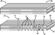
- FIG. 2 is an illustration of a structure 60 that is in the process of being fabricated by an additive manufacturing process, for example, by the machine 10 .
- the structure 60 includes a lower laminate section 62 having four layers 64 that have been formed by laying down side-by-side rows of square filaments on a preceding layer in the manner discussed above, where lines in the layers 64 show the direction of fibers 66 in the filaments and the direction that the filaments are laid down, and where the layers 64 may have a thickness of 1/10,000 of an inch.
- the filaments are laid down 90° relative to each other from one layer 64 to a next layer 64 by rotating the build plate 52 90° each time a layer 64 is completed.
- the filaments are made of a thermoplastic composite, for example, carbon fibers formed in a thermoplastic matrix or resin.
- a needle 70 is inserted through the layers 64 to form holes 72 in the layers 64 and then rods 74 (Z-pins) are inserted into the holes 72 , where the rods 74 have a pointed end 76 and a flat head end 78 .
- the needle 70 can form the holes 72 in any suitable manner.
- the needle 70 can be ultrasonically vibrated to provide heat and insertion energy into the layers 64 , where the composite material of the layers 64 will likely be soft and pliable after just being formed.
- the needle 70 can be heated by a suitable heat source to allow it to be inserted into the layers 64 .
- the rods 74 are carbon fiber pultruded rods.
- the rods 74 can be shorter than the thickness of the section 62 , the same length as the thickness of the section 62 , longer than the thickness of the section 62 so that the flat end 78 sticks up from the section 62 or any combination of these lengths.
- the spacing between the rods 74 and the size of the rods 74 can be application specific for the particular structure 60 being fabricated.
- the rods 74 can be placed at certain areas in the section 62 and not in other areas where reinforcement may not be needed. More specifically, the areal density of the rods 74 can be tailored for a specific application where a higher density of the rods 74 can be at one location and a lower density of the rods 74 can be at another location. For example, the areal density of the rods 74 can be 4% at one location and transition to 0% over a specified area or length of the structure 60 . Further, although the rods 74 are cylindrical in this embodiment, they can be Z-pins of different shapes and configurations in other embodiments.
- the method described above includes the steps of making the holes 72 and then inserting the rods 74 .
- the rods 74 may be made of a sufficient material and be of a sufficient robustness where they can be driven into the layers 64 using, for example, ultrasonic energy without requiring the holes 72 to have already been made.
- a suitable solvent can be used to form openings for the rods 74 .
- the structure 60 can continue to be fabricated. That is illustrated by an upper section 80 having layers 82 formed in the same manner as the section 62 , which would be formed on the section 62 in a layer-by-layer manner as described.
- the layers 82 can be of the same material as the layers 64 or can be of a different material depending on the particular application and design.
- the section 80 Once the section 80 has been formed it too can receive rods in the same manner as the section 62 so that it is also reinforced in the Z-direction. If the ends of the rods 74 are sticking up from the section 62 , such as shown by rod 84 , then the filaments that form the layers 82 can be directed around the rods 74 .
- the location of the rods 74 in the section 80 can be offset from the location of the rods 74 in the section 62 so that they are not aligned with each other.
- the number of layers that are formed before the rods 74 are inserted would depend on a number of factors, such as the thickness of the layers, the layer material, etc.
- FIG. 3 is an illustration of a thermoplastic composite structure 90 that has been manufactured by an additive manufacturing process including layers 92 that have been formed by laying down side-by-side rows of square filaments on a preceding layer in the manner discussed above showing how the layers 92 can be stitched together by rods 94 in a certain reinforcement configuration.
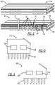
- FIG. 4 is an illustration of a thermoplastic composite structure 100 that has been manufactured by an additive manufacturing process including layers 102 that have been formed by laying down side-by-side rows of square filaments on a preceding layer in the manner discussed above showing how the layers 102 can be stitched together by rods 104 in another reinforcement configuration.
- FIG. 5 is a front view of an end-effector 110 that can replace the end-effector 26 and be coupled to the coupling mechanism 30 on the machine 10 so that the machine 10 can form the holes 72 .
- the end-effector 110 includes a plurality of needles 112 that can be used to simultaneously form a plurality of the holes 72 in the layers 64 .
- An ultrasound or heat source 114 vibrates and/or heats the needles 112 and a device 116 applies downward pressure on the needles 112 to form the holes 72 .
- FIG. 6 is a front view of an end-effector 120 that can replace the end-effector 26 and be coupled to the coupling mechanism 30 on the machine 10 so that the machine 10 can insert the rods 74 into the holes 72 .
- the end-effector 100 includes a plurality of rods 122 that are simultaneously inserted into the plurality of the holes 72 in the layers 64 and released by a release mechanism 124 .
- an ultrasonic source 126 can be employed to vibrate the rods 122 and drive them into the layers 64 without the need to provide the holes 72 .
Landscapes
- Engineering & Computer Science (AREA)
- Chemical & Material Sciences (AREA)
- Materials Engineering (AREA)
- Manufacturing & Machinery (AREA)
- Mechanical Engineering (AREA)
- Composite Materials (AREA)
- Optics & Photonics (AREA)
- Physics & Mathematics (AREA)
- Textile Engineering (AREA)
- Robotics (AREA)
- Ceramic Engineering (AREA)
- Civil Engineering (AREA)
- Structural Engineering (AREA)
- Moulding By Coating Moulds (AREA)
Abstract
Description
- This disclosure relates generally to a method for additively manufacturing a thermoplastic composite structure and, more particularly, to a method for additively manufacturing a thermoplastic composite structure including providing reinforcing Z-pins through layers of the structure.
- Many structural parts and components on aircraft, satellites, spacecraft and other structures need to be light weight and strong in order to satisfy their intended use. In order to meet these requirements, composite structures that include a plurality of laminate layers, such as fiber glass layers, fiber reinforced plastic layers, fiber carbon layers, etc. are often used. For example, some aircraft skin structures include thirty or so laminate layers each having a thickness of about 0.005-0.030 inches. Typically, these composite layers are formed by laying down an interwoven pattern of fibers, such as carbon fibers, that are immersed in a liquid resin, where the resin is cured by heating, which causes it to harden. The several layers are bonded or secured together by a suitable bonding technique, such as co-curing, adhesive bonding, etc.
- One known technique for fabricating some of these parts using carbon fiber composite technologies includes laying down many of the carbon fiber ply layers on a tool, where each ply or sheet of the carbon fiber ply layers includes carbon fibers that have been impregnated with a resin, and where the fibers are woven into a fabric or tape. The carbon fiber ply layers are laid on the tool in a continuous stacked manner, where every group of a predetermined number of the ply layers is subjected to a vacuum and heating step to compress the ply layers together and remove air, which otherwise could result in loss of part integrity. Once all of the ply layers have been built up, a vacuum film or bag is placed over the assembled ply layers and sealed to the tool, where the bag is evacuated to a certain vacuum pressure. The tool and sealed part are then placed in an autoclave or heating oven to cure the resin and form the hardened part.
- The orientation of the fibers in the laminate layers of these types of composite structures typically has high strength in the X and Y direction along the length of the fibers, but has a relatively low strength in the Z-direction across the fibers. Therefore, it is known in the art to provide mechanical fastening devices that are inserted across the layers to provide increased strength in the Z-direction. One well known technique is referred to as Z-pinning that employs Z-pins inserted into and across composite laminate layers in a Z-direction to improve resistance to delamination, increase out of plane shear, and increase damage tolerance by providing reinforcement in the Z-direction of the structure and not relying simply on adhesive bonding.
- A typical Z-pin will be quite small in diameter, such as 0.010-0.020″, where a large number of such Z-pins, for example, 60-600, may be inserted cross-wise into the laminate structure per square inch. In one insertion technique, the Z-pins are partially inserted into a top surface of one of the laminate layers while the laminate layers are in a partially cured or pre-preg state, where the resin is still soft and pliable. An ultrasonic tool is positioned against a group of the Z-pins where the ultrasonic energy creates some level of heating that further softens the resin and allows the Z-pins to be inserted through the laminate layers without interfering with the fibers.
- A traditional Z-pin has a cylindrical shape. However, more modern Z-pins come in variety of shapes and sizes. U.S. Pat. No. 6,514,593 issued to Jones et al., titled Mechanically Locking Z-Pins, assigned to the assignee of this application and herein incorporated by reference, discusses disadvantages of the traditional Z-pin and proposes shaped Z-pins having increased Z-pinning in the Z-direction. Shaped Z-pins typically provide superior performance to traditional cylindrical Z-pins because they reduce pullout from the composite matrix by increasing surface area for adhesive bonding, mechanically locking into the matrix, and locking into the fiber reinforcement. However, because of the shape of these types of Z-pins, they are more difficult to insert into the laminate structure using an ultrasonic tool while the laminate structure is in the pre-preg state because the shape of the Z-pin alters the position of the fibers in the composite layers as they are being inserted. Often, this type of damage to the fibers during insertion of the shaped Z-pins affects the structural integrity of the layer.
- Traditional complex composite fabrication methods, such as autoclave cured hand lay-up, advanced fiber placement, tape placement, etc., are labor intensive, expensive, require a long-lead and expensive tooling and typically require talented fabrication technicians. Therefore, alternate methods have been developed.
- Fused filament fabrication (FFF) is an additive manufacturing (AM) process for 3D printing. More specifically, a FFF process provides a feedstock material, such as a filament from a spool or pellets from a hopper, to a heated nozzle, where it is extruded therefrom as a heated molten filament to be deposited as adjacent rows of strips to form a layer, and where the molten filaments immediately begin to harden once they are extruded from the nozzle. Multiple layers are built up in this manner in a certain configuration to produce a desired part. One known example system is the scalable composite robotic additive manufacturing (SCRAM) system available from Electroimpact, which is an industrial true 6-axis continuous fiber-reinforced 3D printer that enables the tool-less rapid fabrication of aerospace-grade integrated composite structures.
- Various materials can be used as the feedstock material, such as high performance amorphous or semi-crystalline thermoplastics including polyetheretherketone (PEEK), polyetherketoneketone (PEKK), polyphenylsulfone (PPSF or PPSU), polyetherlimdie (PEI) and polyphenylene (PPS). Other materials that may be suitable for FFF include acrylonitrile butadiene styrene (ABS), polylactic acid (PLA), polycarbonate (PC), polyamide (PA), polystyrene (PS), lignin, rubber, carbon fibers, glass fibers, quartz fibers, Kevlar fibers, ultra-high molecular weight polyethylene (UHMWPE), Dyneema, high impact polystyrene (HIPS), nylon, high density polyethylene (HDPE) eutectic materials, plasticine, room temperature vulcanization (RTV) silicon, etc.
- All additive manufactured continuous fiber composite materials fabricated using a placement head and consolidated pre-impregnated filaments or other configured preforms, such as woven strips, braided tubes or the like, will lack interlaminar strength from an absence of interply reinforcement.
- U.S. Pat. No. 9,782,928 issued Oct. 10, 2017 to Barnes et al., assigned to the assignee of this application and herein incorporated by reference, describes a system for reinforcing a thermoplastic polymer workpiece using linear Z-pins that has been at least partially formed by an additive manufacturing process. An ultrasonic energy source applies ultrasonic energy to the Z-pins to ultrasonically heat the Z-pins, and thus locally melt the workpiece material of the subject surface and/or the workpiece body to create a melted workpiece material. One end of the Z-pin is penetrated into the melted workpiece material to create an inserted Z-pin length that is maintained in the workpiece by solidified melted workpiece material around the inserted Z-pin length to reinforce the workpiece.
- The following discussion discloses and describes a method for fabricating a composite part using a 3D printing machine. The method includes forming the part by depositing a plurality of part layers in a consecutive manner on top of each other, where each layer is deposited by laying down rows of filaments made of a thermoplastic composite material. Reinforcing Z-pins are then inserted through the part layers to provide reinforcement of the part in the Z-direction. A plurality of additional part layers are deposited in a consecutive manner on top of each other on the part layers including the reinforcing Z-pins, where each additional part layer is also deposited by laying down rows of filaments made of a thermoplastic composite material. Reinforcing Z-pins are also inserted through the additional part layers to provide reinforcement of the part in the Z-direction. The reinforcing Z-pins can be inserted through the layers to provide any suitable reinforcement configuration.
- Additional features of the disclosure will become apparent from the following description and appended claims, taken in conjunction with the accompanying drawings.
-
FIG. 1 is an isometric view of a 3D printing machine including a robot and an end-effector positioned relative to a part being fabricated on a build plate; -
FIG. 2 is an illustration of a thermoplastic composite layered part being fabricated by an additive manufacturing process and being reinforced by Z-pins; -
FIG. 3 is an illustration of another thermoplastic composite layered part being fabricated by an additive manufacturing process and being reinforced by Z-pins; -
FIG. 4 is an illustration of another thermoplastic composite layered part being fabricated by an additive manufacturing process and being reinforced by Z-pins; -
FIG. 5 is an illustration of an end-effector for the robot shown inFIG. 1 for providing holes in the part that accept the Z-pins; and -
FIG. 6 is an illustration of an end-effector for the robot shown inFIG. 1 for inserting the Z-pins in the holes. - The following discussion of the embodiments of the disclosure directed to a method for additively manufacturing a thermoplastic composite structure including providing reinforcing Z-pins is merely exemplary in nature, and is in no way intended to limit the invention or its applications or uses.
- This disclosure proposes an automated method for reinforcing the interlaminar properties of additive manufactured composite structures by inserting Z-directional rods, tows, pins, filaments or whiskers, referred to herein as Z-pins or rods, into the composite structure employing thermal, mechanical, ultrasonic, chemical (solvent for softening) energy or any combination thereof. The Z-pins are in direct contact with the part surface at the time of insertion of an attachment to the additive manufacturing processing head. The insertion can occur during or after the building process, simultaneously to the additive manufacturing process or in between layer addition. The Z-pin insertions may occur through all or some of the layers and may be staggered by layer or layers and varying of overall area or only certain specific areas of the part. The pin end and at least a portion of the pin body of the Z-pin are penetrated into the hard, melted or softened area of the work piece material and an inserted the majority or all of the Z-pin length. The inserted Z-pin length is maintained in the volume of the material by solidified melted work piece material around the inserted Z-pin length to reinforce the composite structures. This process can be performed either manually or via an automated and/or robotically integrated fabrication system. By inserting Z-pins into the structure during the process of laminating the layers that occurs in the additive manufacturing process, interlaminar re-enforcement will strengthen the structure in the critical through the thickness direction for a structural composite material. It is noted that although thermoplastic composites are the preferred materials for the techniques discussed herein, thermoset composite materials that may have been thermally advanced to behave mechanically and physically in a thermoplastic manner may also be applicable.
-
FIG. 1 is an isometric view of a3D printing machine 10 that is capable of building a part by an FFF process including providing Z-pin insertions as discussed above, where themachine 10 is intended to be merely representative of any additive manufacturing machine capable of performing the methods and processes discussed herein. Themachine 10 includes arobot 12 having abase portion 14, anextension arm 16 coupled to thebase portion 14 by a rotary and pivot joint 18, and a workingarm 20 coupled to theextension arm 16 opposite to thebase portion 14 by an elbow pivot joint 22. An end-effector 26 is coupled to the workingarm 20 at an angle opposite to the joint 22 by a pivot joint 28 having acoupling mechanism 30. Therobot 12 is intended to represent any suitable positioning device for the end-effector 26. The end-effector 26 operates as a print-head assembly for depositing molten filaments for building a complex composite structure as described herein. Various end-effectors can be employed that operate in certain manners and have certain features, and that can be attached to therobot 12. It is noted that during operation, themachine 10 may or may not be positioned within an oven (not shown) so that the temperature of the printing process is controlled. - The end-
effector 26 includes anouter housing 34 and arotatable connector 36 that is releasably connected to thecoupling mechanism 30, and is shown as being transparent to illustrate the various components therein. Those components include a number ofspools 40 on which a plurality offeedstock filaments 42 of various materials are wound, adrive mechanism 44 for selectively and independently drawing thefilaments 42 off of thespools 40, amaterial extruder 48 through which thefilaments 42 are drawn by thedrive mechanism 44, aheater 46 for heating theextruder 48 and melting thefilaments 42, and anozzle 50 for extruding themolten filaments 42 out of the end-effector 26 to be deposited on abuild plate 52 mounted on aplatform 54. Apart 56 is shown being fabricated by themachine 10 as it is being built up in a layer-by-layer manner on asupport structure 58 formed on thebuild plate 52. Thespools 40 can be mounted in the end-effector 26, or mounted remotely with the material being fed to the end-effector 26 through a tube (not shown). Alternately, the stock material can be provided by pellets instead of using thefilament 42. -
FIG. 2 is an illustration of astructure 60 that is in the process of being fabricated by an additive manufacturing process, for example, by themachine 10. Thestructure 60 includes alower laminate section 62 having fourlayers 64 that have been formed by laying down side-by-side rows of square filaments on a preceding layer in the manner discussed above, where lines in thelayers 64 show the direction offibers 66 in the filaments and the direction that the filaments are laid down, and where thelayers 64 may have a thickness of 1/10,000 of an inch. As is apparent, the filaments are laid down 90° relative to each other from onelayer 64 to anext layer 64 by rotating thebuild plate 52 90° each time alayer 64 is completed. The filaments are made of a thermoplastic composite, for example, carbon fibers formed in a thermoplastic matrix or resin. - As discussed above, structures of this type built by an additive manufacturing process may separate between the
layers 64, thus reducing the interlaminar integrity of thestructure 60 in the Z-direction. In order to reinforce thestructure 60, Z-pins are provided in a Z-direction through thelayers 64. To accomplish this in one embodiment, aneedle 70 is inserted through thelayers 64 to formholes 72 in thelayers 64 and then rods 74 (Z-pins) are inserted into theholes 72, where therods 74 have apointed end 76 and aflat head end 78. Theneedle 70 can form theholes 72 in any suitable manner. For example, theneedle 70 can be ultrasonically vibrated to provide heat and insertion energy into thelayers 64, where the composite material of thelayers 64 will likely be soft and pliable after just being formed. Alternately, theneedle 70 can be heated by a suitable heat source to allow it to be inserted into thelayers 64. In one non-limiting embodiment, therods 74 are carbon fiber pultruded rods. Therods 74 can be shorter than the thickness of thesection 62, the same length as the thickness of thesection 62, longer than the thickness of thesection 62 so that theflat end 78 sticks up from thesection 62 or any combination of these lengths. The spacing between therods 74 and the size of therods 74 can be application specific for theparticular structure 60 being fabricated. Additionally, therods 74 can be placed at certain areas in thesection 62 and not in other areas where reinforcement may not be needed. More specifically, the areal density of therods 74 can be tailored for a specific application where a higher density of therods 74 can be at one location and a lower density of therods 74 can be at another location. For example, the areal density of therods 74 can be 4% at one location and transition to 0% over a specified area or length of thestructure 60. Further, although therods 74 are cylindrical in this embodiment, they can be Z-pins of different shapes and configurations in other embodiments. - The method described above includes the steps of making the
holes 72 and then inserting therods 74. In an alternate embodiment, therods 74 may be made of a sufficient material and be of a sufficient robustness where they can be driven into thelayers 64 using, for example, ultrasonic energy without requiring theholes 72 to have already been made. Further, instead of using a needle to form theholes 72, a suitable solvent can be used to form openings for therods 74. - Once the
rods 74 have been inserted into thelayers 64, thestructure 60 can continue to be fabricated. That is illustrated by anupper section 80 havinglayers 82 formed in the same manner as thesection 62, which would be formed on thesection 62 in a layer-by-layer manner as described. Thelayers 82 can be of the same material as thelayers 64 or can be of a different material depending on the particular application and design. Once thesection 80 has been formed it too can receive rods in the same manner as thesection 62 so that it is also reinforced in the Z-direction. If the ends of therods 74 are sticking up from thesection 62, such as shown byrod 84, then the filaments that form thelayers 82 can be directed around therods 74. The location of therods 74 in thesection 80 can be offset from the location of therods 74 in thesection 62 so that they are not aligned with each other. The number of layers that are formed before therods 74 are inserted would depend on a number of factors, such as the thickness of the layers, the layer material, etc. -
FIG. 3 is an illustration of a thermoplasticcomposite structure 90 that has been manufactured by an additive manufacturingprocess including layers 92 that have been formed by laying down side-by-side rows of square filaments on a preceding layer in the manner discussed above showing how thelayers 92 can be stitched together byrods 94 in a certain reinforcement configuration. -
FIG. 4 is an illustration of a thermoplasticcomposite structure 100 that has been manufactured by an additive manufacturingprocess including layers 102 that have been formed by laying down side-by-side rows of square filaments on a preceding layer in the manner discussed above showing how thelayers 102 can be stitched together byrods 104 in another reinforcement configuration. - In a practical implementation,
multiple needles 70 can be used to formmultiple holes 72 at the same time.FIG. 5 is a front view of an end-effector 110 that can replace the end-effector 26 and be coupled to thecoupling mechanism 30 on themachine 10 so that themachine 10 can form theholes 72. The end-effector 110 includes a plurality of needles 112 that can be used to simultaneously form a plurality of theholes 72 in thelayers 64. An ultrasound orheat source 114 vibrates and/or heats the needles 112 and a device 116 applies downward pressure on the needles 112 to form theholes 72. -
FIG. 6 is a front view of an end-effector 120 that can replace the end-effector 26 and be coupled to thecoupling mechanism 30 on themachine 10 so that themachine 10 can insert therods 74 into theholes 72. The end-effector 100 includes a plurality ofrods 122 that are simultaneously inserted into the plurality of theholes 72 in thelayers 64 and released by arelease mechanism 124. For certain applications, anultrasonic source 126 can be employed to vibrate therods 122 and drive them into thelayers 64 without the need to provide theholes 72. - The foregoing discussion discloses and describes merely exemplary embodiments of the present disclosure. One skilled in the art will readily recognize from such discussion and from the accompanying drawings and claims that various changes, modifications and variations can be made therein without departing from the spirit and scope of the disclosure as defined in the following claims.
Claims (20)
Priority Applications (5)
| Application Number | Priority Date | Filing Date | Title |
|---|---|---|---|
| US17/122,343 US11701816B2 (en) | 2020-12-15 | 2020-12-15 | Process for reinforcing continuous fiber additively manufactured laminates |
| TW110137336A TW202224914A (en) | 2020-12-15 | 2021-10-07 | Process for reinforcing continuous fiber additively manufactured laminates |
| PCT/US2021/072893 WO2022133427A1 (en) | 2020-12-15 | 2021-12-14 | Process for reinforcing continuous fiber additively manufactured laminates |
| KR1020237020126A KR20230121606A (en) | 2020-12-15 | 2021-12-14 | Reinforcing method for laminates manufactured by continuous fiber deposition |
| EP21840405.1A EP4263188B1 (en) | 2020-12-15 | 2021-12-14 | Process for reinforcing continuous fiber additively manufactured laminates |
Applications Claiming Priority (1)
| Application Number | Priority Date | Filing Date | Title |
|---|---|---|---|
| US17/122,343 US11701816B2 (en) | 2020-12-15 | 2020-12-15 | Process for reinforcing continuous fiber additively manufactured laminates |
Publications (2)
| Publication Number | Publication Date |
|---|---|
| US20220184880A1 true US20220184880A1 (en) | 2022-06-16 |
| US11701816B2 US11701816B2 (en) | 2023-07-18 |
Family
ID=79288005
Family Applications (1)
| Application Number | Title | Priority Date | Filing Date |
|---|---|---|---|
| US17/122,343 Active 2041-05-12 US11701816B2 (en) | 2020-12-15 | 2020-12-15 | Process for reinforcing continuous fiber additively manufactured laminates |
Country Status (5)
| Country | Link |
|---|---|
| US (1) | US11701816B2 (en) |
| EP (1) | EP4263188B1 (en) |
| KR (1) | KR20230121606A (en) |
| TW (1) | TW202224914A (en) |
| WO (1) | WO2022133427A1 (en) |
Cited By (11)
| Publication number | Priority date | Publication date | Assignee | Title |
|---|---|---|---|---|
| US20230076556A1 (en) * | 2021-09-08 | 2023-03-09 | International Business Machines Corporation | Performing corrective actions during three-dimensional printing jobs |
| CN116330707A (en) * | 2023-02-13 | 2023-06-27 | 福建海源新材料科技有限公司 | HP-RTM fiber cloth laying method |
| CN117661200A (en) * | 2023-12-04 | 2024-03-08 | 中国机械科学研究总院集团有限公司 | Needle punch forming method of preform |
| CN117734163A (en) * | 2023-12-22 | 2024-03-22 | 北京机科国创轻量化科学研究院有限公司 | Z-direction yarn planting method for composite material additive manufacturing |
| CN118046575A (en) * | 2024-04-16 | 2024-05-17 | 南京航空航天大学 | A method for interlayer reinforcement of continuous fiber additive manufacturing based on pressure injection Z-pin structure |
| EP4371746A3 (en) * | 2022-10-31 | 2024-08-07 | Rohr, Inc. | Systems and methods for robotic arm end effector for tailored through thickness reinforcement |
| US20250135714A1 (en) * | 2023-10-31 | 2025-05-01 | Airbus Americas, Inc. | Elastic additive manufactured parts having embedded woven layer for improved wear resistance, durability and electrical conductivity |
| US12297571B2 (en) | 2022-10-31 | 2025-05-13 | Rohr, Inc. | Systems and methods for spray cleaning needles for through thickness reinforcement of resin-infused fabrics |
| US12297572B2 (en) | 2022-10-31 | 2025-05-13 | Rohr, Inc. | Systems and methods for self-cleaning needles for through thickness reinforcement of resin-infused fabrics |
| US12576581B2 (en) * | 2024-04-16 | 2026-03-17 | Nanjing University Of Aeronautics And Astronautics | Interlayer strengthening method for continuous fiber additive manufacturing based on pressure injected Z-pin-like structures |
| US12589525B2 (en) | 2024-01-16 | 2026-03-31 | Goodrich Corporation | In-situ compaction during z-fiber reinforcement of dry fiber preforms |
Family Cites Families (13)
| Publication number | Priority date | Publication date | Assignee | Title |
|---|---|---|---|---|
| GB9212697D0 (en) | 1992-06-15 | 1992-07-29 | Short Brothers Plc | Composite structure manufacture |
| US5868886A (en) | 1995-12-22 | 1999-02-09 | Alston; Mark S. | Z-pin reinforced bonded composite repairs |
| US5980665A (en) | 1996-05-31 | 1999-11-09 | The Boeing Company | Z-pin reinforced bonds for connecting composite structures |
| US6514593B1 (en) | 1999-08-23 | 2003-02-04 | Northrop Grumman Corporation | Mechanically locking Z-pins |
| US7917243B2 (en) * | 2008-01-08 | 2011-03-29 | Stratasys, Inc. | Method for building three-dimensional objects containing embedded inserts |
| GB201117467D0 (en) | 2011-10-11 | 2011-11-23 | Rolls Royce Plc | A method of providing through-thickness reinforcement of a laminated material |
| US20170173868A1 (en) * | 2013-03-22 | 2017-06-22 | Markforged, Inc. | Continuous and random reinforcement in a 3d printed part |
| GB201322276D0 (en) | 2013-12-17 | 2014-01-29 | Rolls Royce Plc | A Reinforcing pin for a laminated composite structure and related methods |
| US9782928B2 (en) * | 2015-09-02 | 2017-10-10 | Northrop Grumman Systems Corporation | Method and system for reinforcing a workpiece |
| WO2018027166A2 (en) * | 2016-08-04 | 2018-02-08 | The Regents Of The University Of Michigan | Fiber-reinforced 3d printing |
| US20190091927A1 (en) * | 2017-09-22 | 2019-03-28 | Ut-Battelle, Llc | Penetrating and actuating nozzle for extrusion-based 3d printing |
| US11203404B2 (en) | 2018-04-19 | 2021-12-21 | The Boeing Company | Composite toughening using three dimensional printed thermoplastic pins |
| US11167483B2 (en) | 2019-04-10 | 2021-11-09 | Northrop Grumman Systems Corporation | Methods and apparatus for fabrication of 3D integrated composite structures |
-
2020
- 2020-12-15 US US17/122,343 patent/US11701816B2/en active Active
-
2021
- 2021-10-07 TW TW110137336A patent/TW202224914A/en unknown
- 2021-12-14 EP EP21840405.1A patent/EP4263188B1/en active Active
- 2021-12-14 WO PCT/US2021/072893 patent/WO2022133427A1/en not_active Ceased
- 2021-12-14 KR KR1020237020126A patent/KR20230121606A/en active Pending
Cited By (14)
| Publication number | Priority date | Publication date | Assignee | Title |
|---|---|---|---|---|
| US12330374B2 (en) * | 2021-09-08 | 2025-06-17 | International Business Machines Corporation | Performing corrective actions during three-dimensional printing jobs |
| US20230076556A1 (en) * | 2021-09-08 | 2023-03-09 | International Business Machines Corporation | Performing corrective actions during three-dimensional printing jobs |
| US12297571B2 (en) | 2022-10-31 | 2025-05-13 | Rohr, Inc. | Systems and methods for spray cleaning needles for through thickness reinforcement of resin-infused fabrics |
| US12404616B2 (en) | 2022-10-31 | 2025-09-02 | Rohr, Inc. | Systems and methods for robotic arm end effector for tailored through thickness reinforcement |
| US12297572B2 (en) | 2022-10-31 | 2025-05-13 | Rohr, Inc. | Systems and methods for self-cleaning needles for through thickness reinforcement of resin-infused fabrics |
| EP4371746A3 (en) * | 2022-10-31 | 2024-08-07 | Rohr, Inc. | Systems and methods for robotic arm end effector for tailored through thickness reinforcement |
| CN116330707A (en) * | 2023-02-13 | 2023-06-27 | 福建海源新材料科技有限公司 | HP-RTM fiber cloth laying method |
| US20250135714A1 (en) * | 2023-10-31 | 2025-05-01 | Airbus Americas, Inc. | Elastic additive manufactured parts having embedded woven layer for improved wear resistance, durability and electrical conductivity |
| US12496768B2 (en) * | 2023-10-31 | 2025-12-16 | Airbus Operations Gmbh | Elastic additive manufactured parts having embedded woven layer for improved wear resistance, durability and electrical conductivity |
| CN117661200A (en) * | 2023-12-04 | 2024-03-08 | 中国机械科学研究总院集团有限公司 | Needle punch forming method of preform |
| CN117734163A (en) * | 2023-12-22 | 2024-03-22 | 北京机科国创轻量化科学研究院有限公司 | Z-direction yarn planting method for composite material additive manufacturing |
| US12589525B2 (en) | 2024-01-16 | 2026-03-31 | Goodrich Corporation | In-situ compaction during z-fiber reinforcement of dry fiber preforms |
| CN118046575A (en) * | 2024-04-16 | 2024-05-17 | 南京航空航天大学 | A method for interlayer reinforcement of continuous fiber additive manufacturing based on pressure injection Z-pin structure |
| US12576581B2 (en) * | 2024-04-16 | 2026-03-17 | Nanjing University Of Aeronautics And Astronautics | Interlayer strengthening method for continuous fiber additive manufacturing based on pressure injected Z-pin-like structures |
Also Published As
| Publication number | Publication date |
|---|---|
| EP4263188B1 (en) | 2025-07-23 |
| WO2022133427A1 (en) | 2022-06-23 |
| EP4263188A1 (en) | 2023-10-25 |
| KR20230121606A (en) | 2023-08-18 |
| US11701816B2 (en) | 2023-07-18 |
| TW202224914A (en) | 2022-07-01 |
Similar Documents
| Publication | Publication Date | Title |
|---|---|---|
| US11701816B2 (en) | Process for reinforcing continuous fiber additively manufactured laminates | |
| EP3548241B1 (en) | Automated fabrication of fibrous preform | |
| AU2020201610B2 (en) | Fabrication of composite laminates using temporarily stitched preforms | |
| KR20210150381A (en) | Method of Fabricating 3D Composite Structures with Smoothing of Support Structures | |
| KR20210150379A (en) | Method of Fabricating Multi-Material Structures for 3D Integrated Composite Structures | |
| KR20210150380A (en) | Methods for Deposition and Fabrication of 3D Integrated Composite Structures | |
| US20190070829A1 (en) | Reinforced fiber laminate sheet, fiber-reinforced resin molded body, and method of manufacturing reinforced fiber laminate sheet | |
| JP6938987B2 (en) | Method for manufacturing reinforcing fiber base material, manufacturing method for reinforcing fiber preform, and manufacturing method for fiber reinforced composite material molded product | |
| US20230046067A1 (en) | Ultrasonic device for compaction allowing coordinated actuation and motion of multiple ultrasonic compaction horns | |
| US11872761B2 (en) | Ultrasonic compaction device using reciprocating disk horns | |
| US11911965B2 (en) | Ultrasonic consolidation of continuous filament materials for additive manufacturing | |
| US11964432B2 (en) | Ultrasonic material placement and compaction device with material passing through the ultrasonic horn element | |
| AU2024210453A1 (en) | Method of automated processing of high-temperature-stable, closed-pore, rigid hard foams |
Legal Events
| Date | Code | Title | Description |
|---|---|---|---|
| AS | Assignment |
Owner name: NORTHROP GRUMMAN SYSTEMS CORPORATION, VIRGINIA Free format text: ASSIGNMENT OF ASSIGNORS INTEREST;ASSIGNORS:BARNES, ERIC G.;THRASHER, TALBOT P.;DOMINICK, TIMOTHY E.;SIGNING DATES FROM 20201214 TO 20201215;REEL/FRAME:054652/0171 |
|
| FEPP | Fee payment procedure |
Free format text: ENTITY STATUS SET TO UNDISCOUNTED (ORIGINAL EVENT CODE: BIG.); ENTITY STATUS OF PATENT OWNER: LARGE ENTITY |
|
| STPP | Information on status: patent application and granting procedure in general |
Free format text: NON FINAL ACTION MAILED |
|
| STPP | Information on status: patent application and granting procedure in general |
Free format text: RESPONSE TO NON-FINAL OFFICE ACTION ENTERED AND FORWARDED TO EXAMINER |
|
| STCF | Information on status: patent grant |
Free format text: PATENTED CASE |
|
| STCF | Information on status: patent grant |
Free format text: PATENTED CASE |