US20220184863A1 - Composite Foam Article - Google Patents
Composite Foam Article Download PDFInfo
- Publication number
- US20220184863A1 US20220184863A1 US17/432,139 US202017432139A US2022184863A1 US 20220184863 A1 US20220184863 A1 US 20220184863A1 US 202017432139 A US202017432139 A US 202017432139A US 2022184863 A1 US2022184863 A1 US 2022184863A1
- Authority
- US
- United States
- Prior art keywords
- mold
- gas discharge
- assembly
- sealing element
- head
- Prior art date
- Legal status (The legal status is an assumption and is not a legal conclusion. Google has not performed a legal analysis and makes no representation as to the accuracy of the status listed.)
- Granted
Links
Images


Classifications
-
- B—PERFORMING OPERATIONS; TRANSPORTING
- B29—WORKING OF PLASTICS; WORKING OF SUBSTANCES IN A PLASTIC STATE IN GENERAL
- B29C—SHAPING OR JOINING OF PLASTICS; SHAPING OF MATERIAL IN A PLASTIC STATE, NOT OTHERWISE PROVIDED FOR; AFTER-TREATMENT OF THE SHAPED PRODUCTS, e.g. REPAIRING
- B29C44/00—Shaping by internal pressure generated in the material, e.g. swelling or foaming ; Producing porous or cellular expanded plastics articles
- B29C44/02—Shaping by internal pressure generated in the material, e.g. swelling or foaming ; Producing porous or cellular expanded plastics articles for articles of definite length, i.e. discrete articles
- B29C44/12—Incorporating or moulding on preformed parts, e.g. inserts or reinforcements
- B29C44/14—Incorporating or moulding on preformed parts, e.g. inserts or reinforcements the preformed part being a lining
- B29C44/16—Incorporating or moulding on preformed parts, e.g. inserts or reinforcements the preformed part being a lining shaped by the expansion of the material
-
- B—PERFORMING OPERATIONS; TRANSPORTING
- B29—WORKING OF PLASTICS; WORKING OF SUBSTANCES IN A PLASTIC STATE IN GENERAL
- B29C—SHAPING OR JOINING OF PLASTICS; SHAPING OF MATERIAL IN A PLASTIC STATE, NOT OTHERWISE PROVIDED FOR; AFTER-TREATMENT OF THE SHAPED PRODUCTS, e.g. REPAIRING
- B29C44/00—Shaping by internal pressure generated in the material, e.g. swelling or foaming ; Producing porous or cellular expanded plastics articles
- B29C44/34—Auxiliary operations
- B29C44/35—Component parts; Details or accessories
- B29C44/351—Means for preventing foam to leak out from the foaming device during foaming
-
- B—PERFORMING OPERATIONS; TRANSPORTING
- B29—WORKING OF PLASTICS; WORKING OF SUBSTANCES IN A PLASTIC STATE IN GENERAL
- B29C—SHAPING OR JOINING OF PLASTICS; SHAPING OF MATERIAL IN A PLASTIC STATE, NOT OTHERWISE PROVIDED FOR; AFTER-TREATMENT OF THE SHAPED PRODUCTS, e.g. REPAIRING
- B29C44/00—Shaping by internal pressure generated in the material, e.g. swelling or foaming ; Producing porous or cellular expanded plastics articles
- B29C44/34—Auxiliary operations
- B29C44/58—Moulds
- B29C44/588—Moulds with means for venting, e.g. releasing foaming gas
-
- B—PERFORMING OPERATIONS; TRANSPORTING
- B29—WORKING OF PLASTICS; WORKING OF SUBSTANCES IN A PLASTIC STATE IN GENERAL
- B29C—SHAPING OR JOINING OF PLASTICS; SHAPING OF MATERIAL IN A PLASTIC STATE, NOT OTHERWISE PROVIDED FOR; AFTER-TREATMENT OF THE SHAPED PRODUCTS, e.g. REPAIRING
- B29C44/00—Shaping by internal pressure generated in the material, e.g. swelling or foaming ; Producing porous or cellular expanded plastics articles
- B29C44/34—Auxiliary operations
- B29C44/36—Feeding the material to be shaped
- B29C44/38—Feeding the material to be shaped into a closed space, i.e. to make articles of definite length
- B29C44/42—Feeding the material to be shaped into a closed space, i.e. to make articles of definite length using pressure difference, e.g. by injection or by vacuum
-
- B—PERFORMING OPERATIONS; TRANSPORTING
- B29—WORKING OF PLASTICS; WORKING OF SUBSTANCES IN A PLASTIC STATE IN GENERAL
- B29K—INDEXING SCHEME ASSOCIATED WITH SUBCLASSES B29B, B29C OR B29D, RELATING TO MOULDING MATERIALS OR TO MATERIALS FOR MOULDS, REINFORCEMENTS, FILLERS OR PREFORMED PARTS, e.g. INSERTS
- B29K2075/00—Use of PU, i.e. polyureas or polyurethanes or derivatives thereof, as moulding material
-
- B—PERFORMING OPERATIONS; TRANSPORTING
- B29—WORKING OF PLASTICS; WORKING OF SUBSTANCES IN A PLASTIC STATE IN GENERAL
- B29L—INDEXING SCHEME ASSOCIATED WITH SUBCLASS B29C, RELATING TO PARTICULAR ARTICLES
- B29L2031/00—Other particular articles
- B29L2031/58—Upholstery or cushions, e.g. vehicle upholstery or interior padding
Definitions
- vents particularly vents in an upper part of the mold are critical to maintain the efficient production of high-quality seat cushions.
- Various methods have been used to time the closing of a vent. The simplest method is to close the vent a fixed time after the mold is poured or closed. However, variation in the foam process can cause the time requirement to change and force the need to periodically adjust the close time. More complex assemblies and methods, such as those that utilize sensors, e.g. temperature, pressure, or proximity sensors, to sense and close the mold have also been employed. However, such complex sensing systems can be unreliable. Further, if vents are utilized along the parting line, design limitations are consigned on the use of the layer. Namely, the layer cannot be extended out to the edges of the seat cushion because it blocks the parting line vents and reduces foam quality, and even causes manufacturing downtime.
- FIGS. 4A-4M are enlarged cross-sectional views of various examples of the sealing element and the retaining elements.
- FIG. 10 is a cross-sectional view of the layer of the composite article pushing against the head of the sealing element.
- the gas discharge port 108 has a circular cross-sectional profile and a diameter that changes.
- the gas discharge port 108 corresponds with the retaining element 118 a and is shaped at a proximal end to have a diameter D PM that is less than a diameter D DM of a distal end of the gas discharge port 108 . That is, the gas discharge port 108 of the example of FIG. 1 has a narrow portion, and a wide portion. In some examples, such as the example of FIG.
- a minimum distance between the edge of the layer 18 and the parting line 124 depend on the type of layer 18 (e.g. the type of cloth) and the dimensional quality of the layer 18 (coming out of forming, e.g. die cutting).
- Layers 18 having higher weight per unit area tend to be “stiffer” and more dimensionally consistent in both the formed and unformed states.
- Layers 18 such as woven or point bonded cloths tend to be more dimensionally consistent than layers 18 such as non-woven cloth but are at the same time poor at forming deeper draws (to handle contours on an outer surface of the composite article 10 ).
- Layers 18 such as cloths which are used with additional layers such as films laminated thereto (e.g.
- a range “of from 0.1 to 0.9” may be further delineated into a lower third, i.e., from 0.1 to 0.3, a middle third, i.e., from 0.4 to 0.6, and an upper third, i.e., from 0.7 to 0.9, which individually and collectively are within the scope of the appended claims, and may be relied upon individually and/or collectively and provide adequate support for specific examples within the scope of the appended claims.
- a range which defines or modifies a range, such as “at least,” “greater than,” “less than,” “no more than,” and the like, it is to be understood that such language includes subranges and/or an upper or lower limit.
Landscapes
- Moulds For Moulding Plastics Or The Like (AREA)
- Mattresses And Other Support Structures For Chairs And Beds (AREA)
- Casting Or Compression Moulding Of Plastics Or The Like (AREA)
- Molding Of Porous Articles (AREA)
Abstract
Description
- The subject patent application claims priority to and all of the benefits of U.S. Provisional Patent Application No. 62/807,292, filed on Feb. 19, 2019, the disclosure of which is hereby incorporated by reference.
- The subject disclosure generally relates to an assembly for molding a composite article including a foam core and a layer as well as a method of forming the composite foam article with the mold.
- Molded articles formed from polyurethane foam are used in the transportation, furniture, sporting goods, building and construction, and many other industries. For example, in the automotive industry, automotive seats are commonly manufactured with polyurethane cushions that are molded to shape and covered.
- As is known in the art, polyurethane foam is formed from the exothermic reaction of an isocyanate-reactive resin composition and an isocyanate in the presence of a blowing agent. The isocyanate-reactive resin composition, the isocyanate, and the blowing agent are collectively known as a polyurethane system.
- To make seat cushions, the polyurethane system is mixed and dispensed into a mold, e.g. a clamshell mold, and the polyurethane system reacts and expands to assume the shape of the mold and thus form the molded seat cushion. During the molding process, the mold must be adequately vented to allow excess carbon dioxide (CO2) and other gasses generated by the exothermic reaction as well as the air present in the mold to exit the mold as the polyurethane system reacts and expands. Without adequate venting, molds often yield seat cushions of poor quality, which need to be reworked or even scrapped. Further, inadequate venting often causes manufacturing downtime. As such, the proper venting of molds is an important factor in the efficient production of high-quality molded seat cushions.
- Over time, venting solutions have been developed for molds that allow for the efficient production of polyurethane foam articles such as a seat cushion. For example, clamshell molds, such as those used to manufacture seat cushions for the automotive industry, have been designed with various vents in the upper part of the mold (typically opened and closed using a pneumatic cylinder) and with various vents at the part line between the upper and lower parts of the mold.
- However, new challenges have arrived. As industry has progressed, automotive seat cushions are now more often co-molded with a layer, e.g. a cloth layer, to provide reinforcement and reduce squeaking at the interface between the polyurethane foam and the seat frame/seat suspension.
- During the molding process, the layer can be used as a venting aid as gas can enter the cloth from various places in the mold and travel through or behind the cloth on its way to a vent. However, vents located behind cloth must be closed after the cavity has been filled and pressure starts building, otherwise the polyurethane foam may penetrate the cloth and cause any combination of the following problems:
-
- the polyurethane may enter and plug the vent thereby causing the vent to fail and causing manufacturing downtime;
- the polyurethane may cause the seat cushion to squeak once incorporated into a seat;
- the polyurethane may form an undesirable nib or protrusion on the seat cushion;
- the polyurethane may densify and no longer act as a cushioning material; and
- if the vent fails to close, delayed foam movement into the cloth can cause inconsistent cell structure and variations in foam density—even cause the polyurethane foam to collapse.
- To this end, the timely closing of vents, particularly vents in an upper part of the mold are critical to maintain the efficient production of high-quality seat cushions. Various methods have been used to time the closing of a vent. The simplest method is to close the vent a fixed time after the mold is poured or closed. However, variation in the foam process can cause the time requirement to change and force the need to periodically adjust the close time. More complex assemblies and methods, such as those that utilize sensors, e.g. temperature, pressure, or proximity sensors, to sense and close the mold have also been employed. However, such complex sensing systems can be unreliable. Further, if vents are utilized along the parting line, design limitations are consigned on the use of the layer. Namely, the layer cannot be extended out to the edges of the seat cushion because it blocks the parting line vents and reduces foam quality, and even causes manufacturing downtime.
- As such, there is a need for a molding assembly that provides adequate venting to allow production of molded composite foam articles including a layer and polyurethane foam such as those used for automotive seats.
- The subject disclosure provides an assembly for molding a composite article including a foam core and a layer. The assembly includes a mold. The mold has an inner surface and at least partially defines a cavity as well as one or more gas discharge ports; each of the one or more gas discharge ports has a passageway opening proximal to the inner surface of the mold. The mold also has one or more retaining elements. The assembly further includes one or more sealing elements moveably engaged with the mold. Each of the one or more sealing elements includes a head and is shaped to engage the retaining element on the mold in the vented position. Further, each of the one or more sealing elements corresponds with each of the one or more gas discharge ports. During use of the mold, expansion of the foam core with the layer thereon in the mold pushes each of the one or more sealing elements from the vented position to a closed position wherein the head of the sealing element seals the corresponding passageway opening and closes the corresponding gas discharge port. Advantageously, the assembly allows for increased design flexibility and efficient and consistent manufacturing of the composite article.
- The advantages of the present disclosure will be readily appreciated, as the same becomes better understood by reference to the following detailed description when considered in connection with the accompanying drawings. It is to be understood that the drawings are purely illustrative and are not necessarily drawn to scale.
-
FIG. 1 is a cross-sectional view of an example of an assembly for molding a composite article. -
FIG. 2 is an enlarged perspective view of a sealing element that is included in the assembly ofFIG. 1 . -
FIG. 3 is an enlarged, isolated cross-sectional view of the sealing element ofFIG. 1 in a vented position illustrating venting of the assembly. -
FIGS. 4A-4M are enlarged cross-sectional views of various examples of the sealing element and the retaining elements. -
FIG. 5A is an enlarged cross-sectional view of an example of a particular sealing element and a corresponding retaining element. -
FIG. 5B is a top view of a head of the sealing element ofFIG. 5A . -
FIG. 6 is a perspective view of an example of the composite article formed with the assembly and method disclosed herein. -
FIG. 7 is a cross-sectional view of the composite article ofFIG. 6 shown along line 6-6. -
FIGS. 8A-8D are a series of schematic illustrations, which show enlarged, isolated cross-sectional views of the sealing element moveably engaged within the gas discharge port, with each of the illustrations describing various aspects of an example of the method disclosed herein. -
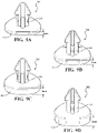
FIG. 9A is an enlarged perspective view of a sealing element having a 1 mm thick head. -
FIG. 9B is an enlarged perspective view of a sealing element having a 2 mm thick head. -
FIG. 9C is an enlarged perspective view of a sealing element having a 3 mm thick head. -
FIG. 9D is an enlarged perspective view of a sealing element having a 4 mm thick head. -
FIG. 10 is a cross-sectional view of the layer of the composite article pushing against the head of the sealing element. - A composite article is disclosed herein and generally shown at 10 throughout the Figures. The
composite article 10 includes a foam core 12 (typically comprising polyurethane) presenting afirst surface 14 and asecond surface 16 facing opposite thefirst surface 14. Thecomposite article 10 includes alayer 18, which is disposed on thefirst surface 14 and/orsecond surface 16 of thefoam core 12. Thecomposite article 10 is particularly suitable for use in interior automotive components such as seats. - It should be appreciated that include, includes, and including are the same as comprise, comprises, and comprising when used throughout this disclosure.
- Although the
composite article 10 of the subject disclosure is particularly useful in the automotive industry, e.g. for use as a seat cushion as described above, thecomposite article 10 of the subject disclosure is not limited to use in the automotive industry. For example, thecomposite article 10 is suitable for use in the aerospace industry, e.g. in airplanes, in the furniture industry, and in the sporting goods industry. - As is known in the art, polyurethane foam is formed from the exothermic reaction of an isocyanate-reactive resin composition and an isocyanate in the presence of a blowing agent. The isocyanate-reactive resin composition, the isocyanate, and the blowing agent are collectively known as a polyurethane system.
- The
foam core 12 typically includes the reaction product of an isocyanate and an isocyanate-reactive component, e.g. an active hydrogen-containing compound such as a polyol, in the presence of a blowing agent. More specifically, thefoam core 12 is formed from the exothermic reaction of an isocyanate-reactive resin composition (including the isocyanate-reactive component) and an isocyanate in the presence of a blowing agent. The isocyanate-reactive resin composition, the isocyanate, and the blowing agent are collectively known as a polyurethane system. Thefoam core 12 can be an isocyanate-based polymer selected from the group of polyurethane, urea-modified polyurethane, and carbodiimide-modified polyurethane. The term “modified”, when used in conjunction with a polyurethane means that up to 50% of the polymer backbone forming linkages have been substituted. Suitable polyurethane foams and systems are commercially available from The Woodbridge Group of Woodbridge, ON. - The
foam core 12 is described as comprising polyurethane foam which is formed from a polyurethane system. However, it should be appreciated that the scope of this disclosure is not limited to composite foam articles including afoam core 12 comprising polyurethane foam and methods for molding such composite foam articles. It will be apparent to those of skill in the art that the present disclosure is applicable to other types of foam chemistry including, but not limited to,foam cores 12 comprising latex foam, neoprene foam, polyvinyl chloride (PVC) foams and methods therewith. - The subject disclosure provides an
assembly 100 for molding thecomposite article 10 including thefoam core 12 and thelayer 18. Theassembly 100 includes amold 102. Themold 102 has aninner surface 104 and at least partially defines amold cavity 106 as well as one or moregas discharge ports 108, each of the one or moregas discharge ports 108 has apassageway opening 110 in fluid communication with themold cavity 106 of themold 102. Thepassageway opening 110 is proximal to theinner surface 104 of themold 102. Theassembly 100 further includes one ormore sealing elements 112 moveably engaged with themold 102. Each of the one ormore sealing elements 112 includes ahead 114 and is shaped to engage a retaining element 118 on themold 102. The retaining element 118 can also be referred to as an engagement element 118. Further, each of the one ormore sealing elements 112 corresponds with each of the one or moregas discharge ports 108. During use of themold 102, expansion of thefoam core 12 with thelayer 18 thereon in themold 102 pushes each of the one ormore sealing elements 112 from a vented position to a closed position wherein thehead 114 of the sealingelement 112 hermetically seals the corresponding passageway opening 110 and closes the correspondinggas discharge port 108. - The one or
more sealing elements 112 typically comprise a polymer. In various examples, the polymer is an elastomer or a thermoplastic elastomer. In many such examples, the elastomer or thermoplastic elastomer exhibits sufficient resilience, flexibility, and other rubber-like physical properties to allow thehead 114 of each of the one ormore sealing elements 112 to hermetically seal thecorresponding passageway opening 110. In other examples, the polymer is a thermoplastic. - In some examples, the one or
more sealing elements 112 comprise a rigid polymer (e.g. a thermoplastic) or metal, and a seal (e.g. an O-ring) is used in cooperation with the sealingelement 112 to achieve a hermetic seal. - In many examples, the sealing
element 112 includes a polymer. Some non-limiting examples of suitable polymers include epoxies, polyurethanes, polyureas, phenolics, polyacrylates, silicones, polysulfides, polyolefins, polyesters, nylons, polyvinylchlorides, latex, styrene-butadiene polymers, nitrile-butadiene polymers, fluoropolymers, mixtures thereof, copolymers thereof, and interpenetrating networks thereof. In many examples, the sealingelement 112 includes silicone. Further, in many such examples, the sealingelement 112 is of unitary construction and formed via injection molding. - In
FIG. 1 is a cross-sectional view of an example of an assembly for molding a composite article is illustrated. More specifically, an example of themold 102 of the subject disclosure is illustrated. The particular two-part mold configuration illustrated is sometimes referred to as a “clamshell”mold 102 by those of skill in the art. The first part 120 (also known in the art as a “bowl”) and the second part 122 (also known in the art as a “lid”) are shaped to engage one another and are joined via a conventional hinge or other means (not shown). More specifically, themold 102 includes thefirst part 120 and thesecond part 122 releasingly engageable between an open position and a closed position. In the closed position, as is shown inFIG. 1 , thefirst part 120 andsecond part 122, when closed, define themold cavity 106, which corresponds to a desired shape, e.g. the shape of an automotive seat cushion. - In
FIG. 1 , the first andsecond parts parting line 124 where the first andsecond parts mold 102 includes one or more parting line vents (not shown), each parting line vent providing a passageway for gas to escape. In some such examples, the parting line vents are in fluid communication with a plurality of interconnected grooves disposed about theinner surface 104 of the mold 102 (network venting). Non-limiting examples of such vents are described in U.S. Pat. No. 7,481,637, the contents of which are incorporated by reference herein. - In many examples, the
mold 102 is free of parting line vents. The venting system of the subject disclosure (which generally refers to the use of various examples of the sealingelement 112 andgas discharge ports 108 disclosed herein) disclosed herein allows for adequate venting without parting line vents. As such, there are fewer design limitations, and thelayer 18 can be extended out of the edges of the seat cushion. - Still referring to
FIG. 1 , themold 102 includes onegas discharge port 108 defined by asidewall 126 in saidmold 102. As is illustrated, thegas discharge port 108 defines thepassageway opening 110 in fluid communication with themold cavity 106 of themold 102. The retaining element 118 projects into the gas discharge port 108 (or the passageway of the gas discharge port 108). In the example ofFIG. 1 , thesidewall 126 of thegas discharge port 108 has the retaining element 118 in the form of ashelf 118 a thereon. -
FIG. 2 is an enlarged perspective view of the sealingelement 112 of theassembly 100 ofFIG. 1 . As is shown inFIG. 3 , thegas discharge port 108 is shaped at a proximal end to have a diameter DPM that is less than a diameter DDM at a distal end of the gas discharge port. For reference, the proximal end of thegas discharge port 108 is located proximal to theinner surface 104 of themold 102 and the distal end of the gas discharge port is located proximal an exterior surface of themold 102. Suchgas discharge ports 108 can be used in conjunction with the sealingelement 112 having astem 116 that is shaped to have a smaller diameter DP at a proximal end adjacent saidhead 114 and a larger diameter DD at a distal end. - Referring again to
FIG. 2 , the sealingelement 112 includes thehead 114 and thestem 116 shaped to engage the retaining element 118 on themold 102 with aChristmas tree retainer 128 a. - In the example of
FIGS. 1-3 , theChristmas tree retainer 128 a has a single discontinuous skirt including 4 portions. Nonetheless, various non-limiting examples of the Christmas tree style retainers are contemplated herein including theChristmas tree retainers 128 a having a continuous skirt which continuously extends radially around thestem 116, a discontinuous skirt which has 4 portions as is shown inFIG. 2 , or a discontinuous skirt which has 3 portions, etc. In various examples, theChristmas tree retainer 128 a of the sealingelement 112 can have from 1 to 5 portions, and from 1 to 10, alternatively from 2 to 7 conical skirts. That said, in many examples, regardless of its configuration, theChristmas tree retainer 128 a cooperates with the retaining element/shelf 118 a in thegas discharge port 108 to enable the venting system to function. - Of course, it should be appreciated that the language “shaped to engage”, which in the example of
FIG. 1 describes the Christmastree style retainer 128, can describe various other shaped configurations, some of which are set forth in the example vents ofFIG. 4 . Thestem 116 having theretainer 128 thereon is slidably engaged in thegas discharge port 108 and cooperates with the retaining element 118, e.g. theshelf 118 a. Broadly stated, thestem 116 is shaped to engage the retaining element 118 on themold 102, and the stem is slidably engaged in thegas discharge port 108 and is also slidably engaged with (and cooperates with) the retaining element 118. As illustrated inFIGS. 1 and 2 , in the vented position, a base of the Christmastree style retainer 128 a sits on the shelf 118 and thehead 114 hangs below thepassageway opening 110 to allow excess CO2 and other gasses generated by the exothermic reaction as well as the air present in themold 102 to exit themold 102 through thegas discharge port 108 as the polyurethane system reacts and expands. - As the polyurethane system reacts and expands in the
mold cavity 106, it pushes thelayer 18 towards theinner surface 104 of themold 102. In turn, thelayer 18 pushes thehead 114 of the sealingelement 112 onto theinner surface 104 of themold 102 and into thepassageway opening 110, wherein thehead 114 of the sealingelement 112 hermetically seals the corresponding passageway opening 110 and closes the correspondinggas discharge port 108. - During use of the
mold 102, expansion of thefoam core 12 with thelayer 18 thereon in themold 102 pushes each of the one ormore sealing elements 112 from the vented position to the closed position wherein thehead 114 of the sealingelement 112 hermetically seals the corresponding passageway opening 110 and closes the correspondinggas discharge port 108. As such, thehead 114 should have a perimeter or profile that is larger than the perimeter of the passageway opening 110 (notched or not notched) of thegas discharge port 108. -
FIG. 3 is an enlarged, isolated cross-sectional view of the sealingelement 112 ofFIG. 1 , which is in the vented position with the arrows representing the airflow out of themold 102 or venting of themold 102. In other words, when the sealingelement 112 is in the vented position, themold cavity 106 is in fluid communication with the air outside of themold 102 via thegas discharge port 108 and venting of themold cavity 106 of themold 102 proceeds. When thecomposite article 10 is formed and the sealingelement 112 is pushed into thepassageway opening 110 to hermetically seal and close the correspondinggas discharge port 108, fluid communication is suspended and venting of themold 102 ceases. - Still referring to
FIG. 3 , it should be appreciated the language “shaped to engage”, which in the example ofFIG. 3 refers to theChristmas tree retainer 128 a, can also refer to various other shaped configurations and is not limited to aChristmas tree retainer 128 a. Likewise, the language “the retaining element” 118, which in the example ofFIG. 3 refers to theshelf 118 a, can also refer to various other shaped configurations and is not limited to ashelf 118 a. Many examples of thesubject assembly 100 include the sealingelement 112 wherein thestem 116 is shaped to have a smaller diameter DP at a proximal end and a larger diameter DD at a distal end, and thegas discharge port 108 is integrated with the retaining element 118 and is shaped at a proximal end to have a diameter DPM greater than the diameter of the proximal DP end of the sealingelement 112. Thegas discharge ports 108 can be used in conjunction with the sealingelement 112 having astem 116 that is shaped to have a smaller diameter at a proximal end adjacent saidhead 114 and a larger diameter at a distal end. - Referring now to
FIG. 10 , an isolated cross-sectional view of the sealingelement 112 is illustrated with thelayer 18 abutting anouter surface 142 of thehead 114 thereby pushing the sealingelement 112 into thegas discharge port 108 and cutting off fluid communication to cease venting of themold 102. InFIG. 10 , just like inFIG. 3 , thegas discharge port 108 is formed with a threaded insert (not numbered). Also, inFIG. 10 , the passageway opening 110 of thegas discharge port 108 is notched to a depth where thehead 114 of the sealingelement 112 “stands proud” of theinner surface 104 of themold 102. - Various non-limiting examples of the sealing
element 112 and the retaining element 118 are illustrated in the examples ofFIGS. 4A-4M . More specifically,FIGS. 4A-4M are partial cross-sectional views of various examples of the sealingelement 112 and the retaining element 118 which can be mixed and matched in any combination to arrive at the venting solution of this disclosure. - In a typical example, the
gas discharge port 108 has a circular cross-sectional profile. In other words, thegas discharge port 108 is a tubular cavity having a circular cross-sectional profile that is formed in themold 102. Of course, thegas discharge port 108 is not limited to a circular cross-sectional profile (or tubular cavity). In various examples, thegas discharge port 108 has an elliptical, rectangular, or triangular cross-sectional profile. In some examples, thegas discharge port 108 includes portions having different shapes (e.g. agas discharge port 108 having a first portion with a circular cross-sectional profile, and a second portion with a rectangular cross-sectional profile). In some examples, thegas discharge port 108 includes portions having different sizes (e.g. agas discharge port 108 having a first portion with a circular cross-sectional profile having a first diameter, and a second portion with a circular cross-sectional profile having a second diameter which is different than (greater than or less than) the first diameter). - In many examples such as that of
FIG. 1 , thegas discharge port 108 has a circular cross-sectional profile and a diameter that changes. For example, with reference toFIG. 3 , thegas discharge port 108 corresponds with the retainingelement 118 a and is shaped at a proximal end to have a diameter DPM that is less than a diameter DDM of a distal end of thegas discharge port 108. That is, thegas discharge port 108 of the example ofFIG. 1 has a narrow portion, and a wide portion. In some examples, such as the example ofFIG. 1 , when thegas discharge port 108 includes portions of different diameter, the transition between the two or more portions of different diameter is stepped at a 90° angle to define a shelf or step perpendicular to thesidewall 126 of thegas discharge port 108. In other examples, the transition between portions of different diameter is gradual or tapered, e.g. at 45° to thesidewall 126 of thegas discharge port 108. Of course, in the vented position, the retainingelement 118 a of the sealingelement 112 sits on the shelf. - In some examples, the
gas discharge port 108 does not change size or shape at thepassageway opening 110. In other examples, a notch is recessed in theinner surface 104 of themold 102 and in fluid communication with the passageway opening 110 of saidgas discharge port 108.FIGS. 3, 4A, and 4B illustrate examples of thegas discharge port 108 that do not change size or shape at thepassageway opening 110, wherein the passageway opening 110 of thegas discharge port 108 is not notched. However, in other examples, such as those illustrated inFIGS. 4C-4M , the passageway opening 110 of thegas discharge port 108 is notched. The notch can be formed of different shapes and sizes and can extend various depths, e.g. from 0.1 to 4 mm, along a longitudinal axis of thegas discharge port 108 into thesecond part 122 of themold 102. The notchedpassageway opening 110 can be beveled, e.g. formed with walls at a 45° angle relative to the longitudinal axis of thegas discharge port 108, as is illustrated inFIG. 4C . The notch can be formed with walls substantially parallel to the longitudinal axis of thegas discharge port 108, as is illustrated inFIGS. 4D-4L . The examples ofFIGS. 3, 4A, and 4B illustrate thepassageway opening 110 that is not notched. -
FIG. 4A illustrates an enlarged cross-sectional view of an example of theassembly 100 including the hingedsealing element 112 and thegas discharge port 108 having a uniform circular cross-sectional profile from thepassageway opening 110 extending longitudinally to its proximal end, which opens to the exterior of themold 102.FIG. 4A illustrates the sealingelement 112 with thehinge 118 b as opposed theChristmas tree retainer 128 a andshelf 118 a illustrated inFIGS. 1-3 . The retaining element 118 of this example is ahinge 118 b on theinner surface 104 of themold 102 located proximal to the passageway opening 110 of thegas discharge port 108. Of course, the sealingelement 112 is shaped to engage thehinge 118 b on themold 102 with anappropriate retainer 128 b. - The sealing
element 112 ofFIG. 4A includes thehead 114 and is shaped to engage thehinge 118 b. The sealingelement 112 is moveably engaged with themold 102. During use of themold 102, expansion of thefoam core 12 with thelayer 18 thereon in themold 102 pushes each of the hinged sealingelements 112 from the vented position (hanging down via the force of gravity) to the closed position wherein thehead 114 of the sealingelement 112 is pushed upward to hermetically seal thepassageway opening 110 and close thegas discharge port 108. Of course, in the vented position, thehead 114 of the sealingelement 112 hangs below thepassageway opening 110 to allow excess CO2 and other gasses generated by the exothermic reaction as well as the air present in themold 102 to exit themold 102 through thegas discharge port 108 as the polyurethane system reacts and expands, but pushed upward in timely fashion to seal themold 102 and produce thecomposite article 10 of high quality. - In some examples, the one or more engagement slots 118 define an opening in the
inner surface 104 of themold 102 outside of the passageway opening and each of said one ormore sealing elements 112 comprises one or more stems 116 which cooperate with the one or more engagement slots 118. In such embodiments, each of the one or moregas discharge ports 108 is located proximal to the one or more retaining elements 118 includingengagement slots 118 c defining an opening in theinner surface 104 of thesecond part 122 of themold 102. Each of the one ormore sealing elements 112 includes one or more stems 116, which cooperate with the one ormore engagement slots 118 c. In some examples, such as the example ofFIG. 4B , each of the one ormore engagement slots 118 c define an opening in theinner surface 104 of themold 102 that does not extend to an exterior of themold 102. In other examples, not shown, the one ormore engagement slots 118 c define an opening in theinner surface 104 of themold 102 and a cavity that extends to the exterior of themold 102. -
FIG. 4B illustrates one such example of theassembly 100 including the sealingelement 112 including thehead 114 and multiple stems 116, which cooperate with themultiple engagement slots 118 c. Thegas discharge port 108 of this example is proximal to theengagement slots 118 c and generally centered with respect to the head 114 (thehead 114 is generally centrally located on the longitudinal axis of the gas discharge port 108). In this example, thestem 116 has ahook 128 c and is thus shaped to engage the retaining element 118/notchedengagement slots 118 c and designed to cooperate with the notch in theengagement slot 118 c. In this example, thegas discharge port 108 has a uniform circular cross-sectional profile from thepassageway opening 110 extending longitudinally towards its proximal end, which opens to the exterior of themold 102. The retaining element 118 is the notchedengagement slots 118 c located on theinner surface 104 of themold 102 proximal to the passageway opening 110 of thegas discharge port 108. LikeFIG. 4A and in contrast to the example ofFIG. 1 ,FIG. 4B illustrates anengagement slot 118 c which is not integral with thegas discharge port 108. - Still referring to
FIG. 4B , the sealingelement 112 is moveably engaged with themold 102. During use of themold 102, expansion of thefoam core 12 with thelayer 18 thereon in themold 102 pushes the sealingelement 112 from the vented position (hanging down via the force of gravity with the hooked stem resting at the bottom of the notch in theengagement slot 118 c) to the closed position wherein thehead 114 of the sealingelement 112 is pushed up (with the hooked stem forced upward to the top of the notch in theengagement slot 118 c) and hermetically seals thepassageway opening 110 and closes thegas discharge port 108. Of course, in the vented position, thehead 114 of the sealingelement 112 hangs below thepassageway opening 110 to allow excess CO2 and other gasses generated by the exothermic reaction as well as the air present in themold 102 to exit themold 102 through thegas discharge port 108 as the polyurethane system reacts and expands, but pushed upward into thepassageway opening 110 in timely fashion to seal themold 102 and produce acomposite article 10 of high quality. - Referring now to
FIGS. 5A and 5B , and example of the venting system of the subject disclosure is shown which is similar to the example ofFIG. 4B but instead of the sealingelement 112 which includes multiple stems 116, which cooperate with themultiple engagement slots 118 c, thehead 114 of the sealingelement 112 of this example is “shaped to engage” the mold surface with aradial retainer 128 e, which cooperates with aradial slot 118 d in theinner surface 104 of themold 102. Thepassageway opening 110 of thegas discharge port 108 of this example is framed by theradial slot 118 d. Further, the passageway opening 110 of thegas discharge port 108 of this example is generally centered with respect to the head 114 (thehead 114 is generally centrally located on the longitudinal axis of the gas discharge port 108). Furthermore, thehead 114 includes one ormore apertures 130, which are located such that they do not overlap with thepassageway opening 110. When the sealingelement 112 is in the vented position, a hook of theradial retainer 128 e sits on the shelf of theradial slot 118 d, and thehead 114 hangs below thepassageway opening 110 to allow excess CO2 and other gasses generated by the exothermic reaction of the polyurethane system as well as the air present in themold 102 to enter into the one ormore apertures 130, flow between theinner surface 104 of themold 102 and theinner surface 136 of thehead 114, and to exit themold 102 through thegas discharge port 108. As the polyurethane system reacts and expands in themold cavity 106, it pushes thelayer 18 towards theinner surface 104 of themold 102. In turn, thelayer 18 pushes thehead 114 of the sealingelement 112 onto theinner surface 104 of themold 102, theapertures 130 are sealed/plugged and so is thepassageway opening 110, wherein thehead 114 of the sealingelement 112 is engaged and the vent system is closed. -
FIG. 4C is a close-up cross-sectional view of an example of theassembly 100 having the shelved 118 agas discharge port 108 and the sealingelement 112 including thehead 114 having a circular profile at a proximal end of thesingle stem 116 and theChristmas tree retainer 128 a at a distal end of thestem 116. Like the example ofFIG. 1 , theChristmas tree retainer 128 a cooperates with the retaining element/shelf 118 a in thegas discharge port 108, i.e., the narrowing of the diameter DPM of thegas discharge port 108 at its proximal end. In this example, the passageway opening 110 of thegas discharge port 108 is notched with beveled edges. Further, thehead 114 having a circular profile has an outer edge that is profiled to mate with the beveled edges of the notched passageway opening 110 of thegas discharge port 108. Of course, the subject disclosure contemplates various such examples where the edges of the notched passageway opening 110 mate with the outer profile of thehead 114 of the sealingelement 112. - Still referring to
FIG. 4C , the sealingelement 112 is moveably engaged within thegas discharge port 108 in themold 102. During use of themold 102, expansion of thefoam core 12 with thelayer 18 thereon pushes sealingelement 112 from the vented position (hanging down via the force of gravity with the bottom conical skirt of theChristmas tree retainer 128 a resting on the retaining element/shelf 118 a in the gas discharge port 108) to the closed position wherein thehead 114 of the sealingelement 112, thestem 116, and theChristmas tree retainer 128 a are forced upward such that thehead 114 of the sealingelement 112 hermetically seals thepassageway opening 110 and closes thegas discharge port 108. - Referring now to
FIG. 4D , a close-up cross-sectional view of an example of theassembly 100 having the shelfed 118 agas discharge port 108 and the sealingelement 112 including thehead 114 having a circular profile at a proximal end of thesingle stem 116 and abow retainer 128 d at a distal end of thestem 116 is illustrated. Like the example ofFIG. 4C , thebow retainer 128 d cooperates with the retaining element/shelf 118 a in thegas discharge port 108. In this example, the passageway opening 110 of thegas discharge port 108 is notched, the notch having a circular profile with squared edges. Thehead 114 has a circular profile, which extends past the circular perimeter of the notchedpassageway opening 110. The subject disclosure contemplates various examples where thehead 114 does not mate with, but extends past, the perimeter of the passageway opening 110 (notched or not) a distance from about 0.1 to about 10, alternatively from about 1 to about 5, mm past the perimeter of thepassageway opening 110. - Still referring to
FIG. 4D , the sealingelement 112 is moveably engaged within thegas discharge port 108 in themold 102. During use of themold 102, expansion of thefoam core 12 with thelayer 18 thereon pushes the sealingelement 112 from the vented position (hanging down via the force of gravity with the bottom of thebow retainer 128 d resting on the retaining element/shelf 118 a in the gas discharge port 108) to the closed position wherein thehead 114 of the sealingelement 112, thestem 116, and thebow retainer 128 d are forced upward such that thehead 114 of the sealingelement 112 hermetically seals thepassageway opening 110 and closes thegas discharge port 108. - Referring now to
FIG. 4E , a close-up cross-sectional view of an example of theassembly 100 having the shelfed 118 agas discharge port 108 and the sealingelement 112 including thehead 114 having a circular profile at a proximal end of thesingle stem 116 and abow retainer 128 d at a distal end of thestem 116 is illustrated.FIG. 4E is just like the example ofFIG. 4D , but the sealingelement 112 is formed from a more rigid polymer (hence the different hashing thanFIG. 4D ) and thehead 114 cooperates with a seal (an O-ring 132) when in the closed position to seal thepassageway opening 110 and closes thegas discharge port 108. It should be appreciated that the O-ring 132 shown inFIG. 4E could can be located on theinner surface 136 of thehead 114 as opposed to being located on theinner surface 104 of themold 102 as shown inFIG. 4E . - Referring now to
FIG. 4F , a close-up cross-sectional view of an example of theassembly 100 having the shelfed 118 agas discharge port 108 and the sealingelement 112 including thehead 114 having a circular profile at a proximal end of thesingle stem 116 and theChristmas tree retainer 128 a at a distal end of thestem 116 is illustrated. In this example, theChristmas tree retainer 128 a has six conical skirts (in contrast to the three conical skirts of theChristmas tree retainer 128 a of the sealingelement 112 ofFIG. 4C ).Christmas tree retainer 128 a cooperates with the retaining element/shelf 118 a in thegas discharge port 108. Further, the passageway opening 110 of thegas discharge port 108 is notched, the notch having a circular profile with squared edges. Thehead 114 has a circular profile, which extends past the circular perimeter of the notchedpassageway opening 110. - Still referring to
FIG. 4F , the sealingelement 112 is moveably engaged within thegas discharge port 108 in themold 102. The sealingelement 112 is held in position via gravity in the vented position. During use of themold 102, expansion of thefoam core 12 with thelayer 18 thereon pushes the sealingelement 112 from the vented position (hanging down via the force of gravity with the bottom conical skirt of theChristmas tree retainer 128 a resting on the retaining element/shelf 118 a in the gas discharge port 108) to the closed position wherein thehead 114 of the sealingelement 112, thestem 116, and theChristmas tree retainer 128 a are forced upward such that thehead 114 of the sealingelement 112 hermetically seals thepassageway opening 110 and closes thegas discharge port 108. - Referring now to
FIG. 4G , a close-up cross-sectional view of an example of theassembly 100 having the shelfed 118 agas discharge port 108 and the sealingelement 112 including thehead 114 having a circular profile at a proximal end of thesingle stem 116 and theChristmas tree retainer 128 a at a distal end of thestem 116 is illustrated. In this example, theChristmas tree retainer 128 a has two conical skirts (in contrast to the six conical skirts of theChristmas tree retainer 128 a of the sealingelement 112 ofFIG. 4F ). Like the example ofFIG. 4G , theChristmas tree retainer 128 a cooperates with the retaining element/shelf 118 a in thegas discharge port 108. In this example, the passageway opening 110 of thegas discharge port 108 is notched, the notch having a circular profile with squared edges. Further, thehead 114 has a circular perimeter, which extends past the circular perimeter of the notchedpassageway opening 110. - Still referring to
FIG. 4G , the sealingelement 112 is moveably engaged within thegas discharge port 108 in themold 102. During use of themold 102, expansion of thefoam core 12 with thelayer 18 thereon pushes the sealingelement 112 from the vented position (hanging down via the force of gravity with the bottom conical skirt of theChristmas tree retainer 128 a resting on the retaining element/shelf 118 a in the gas discharge port 108) to the closed position wherein thehead 114 of the sealingelement 112, thestem 116, and theChristmas tree retainer 128 a are forced upward such that thehead 114 of the sealingelement 112 hermetically seals thepassageway opening 110 and closes thegas discharge port 108. - The
assembly 100 of the example ofFIG. 4H includes the shelfed 118 agas discharge port 108 and the sealingelement 112 including thehead 114 having a circular profile at a proximal end of thesingle stem 116 and theChristmas tree retainer 128 a at a distal end of thestem 116. Theassembly 100 ofFIG. 4H is just like that ofFIG. 4F with the exception being that the O-ring 132 is embedded in theinner surface 104 of themold 102 about the perimeter of thepassageway opening 110.FIG. 4E similarly utilizes the O-ring 132 too. In the closed position, thehead 114 of the sealingelement 112 rests against the O-ring 132 to facilitate a hermetical seal when thehead 114 of the sealingelement 112 is in the closed position. In some examples, the sealingelement 112 is held in the vented position or biased via abiasing element 134 such as a spring. Theassembly 100 of the example ofFIG. 4I includes the shelfed 118 agas discharge port 108 and the sealingelement 112 including thehead 114 having a circular profile at a proximal end of thesingle stem 116 and theChristmas tree retainer 128 a at a distal end of thestem 116. Theassembly 100 ofFIG. 4I is just like that ofFIG. 4H with the exception being that the sealingelement 112 is spring loaded in the vented position (as opposed to being gravity loaded) with aspring 134 which is disposed between aninner surface 136 of thehead 114 and abottom surface 138 of the notchedpassageway opening 110. Theassembly 100 ofFIG. 4J is just like that ofFIG. 4I with the exception being that theChristmas tree retainer 128 a ofFIG. 4J includes only three conical skirts rather than the six conical skirts included in theChristmas tree retainer 128 a ofFIG. 4I . - It should be appreciated that any of the elements of the example of
FIGS. 4A-4M can be mixed and matched to arrive at theassembly 100 of this disclosure. To this end, the various sealingelements 112 disclosed and contemplated herein can be gravity loaded or spring loaded. Either way, especially in examples in which thesealing element 112 is gravity loaded, the weight of the sealingelement 112 may vary. - In various examples, the weight of the sealing
element 112 is greater than about 0.2, greater than about 0.3, greater than about 0.4, greater than about 0.5, from about 0.2 to about 30, from about 0.4 to about 15, or from about 0.5 to about 10, grams. In various non-limiting examples, all values and ranges of values including and between those described above are hereby expressly contemplated for use herein. - The
assembly 100 ofFIG. 4K is just like that ofFIG. 4H with the exception being that the sealingelement 112 includes afastener 140, e.g. hooks (hook with loops on the head 114), adhesive, etc., on theouter surface 142 of itshead 114. Thefastener 140 is configured to releasably connect with thelayer 18. As such, thefastener 140 facilitates contact between thelayer 18 of thecomposite article 10 and the sealingelement 112 during use of theassembly 100. In other words, in this example, the fastener 140 (or hooks thereof) attaches to thelayer 18 so when the mold lid opens/disengages, the hooks are pulled by thelayer 18 causing sealingelement 112 to be pulled down away from thegas discharge port 108 such that thehead 114 of the sealingelement 112 is pulled away from thepassageway opening 110 and venting is opened in preparation for the mold's 102 next use. - It should be appreciated that this concept of including a hook fastener(s) (e.g. a Velcro like surface) on the
outer surface 142 of thehead 114 which is configured to releasably connect with the layer can be used in anyexample sealing element 112 described herein. - The
assembly 100 ofFIG. 4L is just like that ofFIG. 4H with the exception being that the sealingelement 112 ofFIG. 4L includes thehead 114 which is contoured or bowed rather than straight. The bowedhead 114 causes the seal to break when pressure is released from thehead 114. During use of theassembly 100, this example of thehead 114 facilitates contact and a robust hermetic seal between theinner surface 136 of thehead 114 and theinner surface 104 of themold 102 via resilience imparted on thehead 114 via the contour. Theassembly 100 ofFIG. 4L is just like that ofFIG. 4L with the exception being that theChristmas tree retainer 128 a ofFIG. 4M includes only three conical skirts rather than the six conical skirts included in theChristmas tree retainer 128 a ofFIG. 4L . It should be appreciated that the various sealingelements 112 disclosed and contemplated herein can have the sealingelement 112 having thehead 114 having various thicknesses. Thickness impacts performance, because the weight of the sealingelement 112 is critical to function in consideration ofmold 102 pressures. With respect to polymeric sealing elements (e.g. comprising silicone), ahead 114 having a thickness of 1 mm can be too light, causing early closure of the vent which results in underfill of themold cavity 106, which causes poor quality composite articles 10 (e.g. seat cushions) and even scrapcomposite articles 10. However, thehead 114 having a thickness of 2, 3, or 4, mm silicone performs well to produce high qualitycomposite articles 10. - The
head 114 typically has a thickness of greater than 0.25 mm. That said, in various examples, thehead 114 has a thickness of from about 0.25 to about 6, from about 0.5 to about 4, from about 1.5 to about 4, from about 0.75 to about 3, from about 1.5 to about 3, mm. Referring now toFIGS. 9A-D , the sealingelement 112 having thehead 114 having a thickness of 1 mm (9A), 2 mm (9B), 3 mm (9C) and 4 mm (9D) are illustrated. In various non-limiting examples, all values and ranges of thickness values including and between those described above are hereby expressly contemplated for use herein. - From a problem solution perspective, embodiments of the sealing
element 112, retaining element 118, and thegas discharge port 108 that are gravity activated (the sealingelement 112 is held in the vented position via gravity), have sufficient weight, and comprise an elastomer such as silicone eliminate the need for electrically timed venting on molds which can be problematic. Further, such embodiments of the sealingelement 112 remain moveably engaged thegas discharge port 108 and function efficiently over a number of use cycles becausesuch sealing elements 112 exhibit surface characteristics such as a coefficient of friction and surface energy associated with elastomers such as silicone that facilitate prolonged use. Stated simply, such engagement elements work efficiently over as long period of time without gumming up and causing venting problems and ultimately quality problems with thecomposite article 12. - Referring now to
FIG. 6 , thecomposite article 10 formed with theassembly 100 is also disclosed herein.FIG. 7 is a cross-sectional view of thecomposite article 10 ofFIG. 6 shown along line 6-6. Thecomposite article 10 includes thefoam core 12 presenting thefirst surface 14 and thesecond surface 16 facing opposite thefirst surface 14. Thefoam core 12 of thecomposite article 10 typically includes polyurethane and can also be referred to as apolyurethane foam core 12. Various polyurethane foam and systems therefore are described above. - Referring now to
FIG. 6 , thecomposite article 10 also includes thelayer 18. Thelayer 18 can include various materials including cloth comprising natural and/or synthetic fibers and single piece polymeric materials. Thelayer 18 can be permeable or impermeable (non-permeable), woven, non-woven, or a polymeric film. - Of course, the
layer 18 can include multiple sub-layers. If included, the sub-layers can be compositionally the same or compositionally different. Further, the sub-layers can be permeable or impermeable. Of course, the sub-layers can be woven or non-woven. - In some examples, the
layer 18 is permeable. That is, thelayer 18 allows gas to pass therethrough. A woven,permeable layer 18 is preferred when forming is required. - In other examples, the
layer 18 is impermeable. Impermeable layers can be utilized to contain air in cooperation with seat ventilation systems. Such impermeable layers are often bi-laminate (include 2 sub-layers) or tri-laminate (include 3 sub-layers). Of course, the sub-layers can be woven or non-woven. - In some examples where the
layer 18 is impermeable, thelayer 18 can include various, slits, holes and cut outs to provide for adequate out-flow of gas and venting of themold 102. In other examples, air flow occurs at the edges of thelayer 18. In addition, various venting features can be incorporated in themold 102 such as edge venting and network venting (previously described) to further facilitate the outflow of gas and venting of themold 102. - Both woven and non-woven layers are typically permeable. Films or thin solid sheets of material form layer or sub layer are impermeable. Examples of the
layer 18 that are impermeable typically comprise a laminate include a plurality of layer including a polymeric film layer. In some examples, the polymeric film layer is sandwiched between two non-woven layers. The non-woven layer against the mold surface can be used to transfer gasses to a vent while the non-woven on the foam core side will enhance bonding of thelayer 18 to thefoam core 12. - When impermeable, the
layer 18 which can also be a film or multiple films serving different purposes. One purpose could be to adhere thelayer 18 well to thefoam core 12 while allowing thelayer 18 to slide silently over a seat frame. When thelayer 18 includes a film (and is thus impermeable) and does not include woven or non-woven sub layers venting becomes necessary to transfer gasses to vent(s). If there is no network vent thelayer 18 will seal off against theinner surface 104 of themold 102 when thefoam core 12 presses against themold 102 to stop gas transfer/venting. - In various examples, the weight per area of the
layer 18 is from about 100 to about 800, from about 140 to about 650, or from about 140 to about 450, g/m2 (gsm). Thelayer 18 can have various stiffnesses and is typically somewhat stiff as is illustrated inFIG. 10 . In various non-limiting examples, all values and ranges of values for the weight per unit area of thelayer 18 including and between those described above are hereby expressly contemplated for use herein. - A method of molding a
composite article 10 including thefoam core 12 and thelayer 18 with theassembly 100 is also disclosed herein. Theassembly 100 and thecomposite article 10 are just as described above. - The method includes the steps of: providing the mold 102 (just as described above); providing the one or more sealing elements 112 (just as described above); engaging each of the one or
more sealing elements 112 with each of the one or more retaining elements 118 to retain the sealing element in the mold in a vented position; inserting thelayer 18 into themold 102; injecting the polyurethane system into themold 102; and reacting the polyurethane system to form thefoam core 12, wherein the exothermic reaction and expansion of the components of the polyurethane system in themold cavity 106 pushes thelayer 18 into the one ormore sealing elements 112 to move the one ormore sealing elements 112 from the vented position to the closed position such that thehead 114 of the sealingelement 112 hermetically seals thegas discharge port 108 to prevent further venting and form thecomposite article 10. - In some examples, the method includes the step of disengaging the first and second parts and moving the first and
second parts inner surface 104 of themold 102. Once open, the layer 18 (and any additional layers) is inserted into themold 102. The venting system of the subject disclosure enables venting through the entire extent of thelayer 18. Advantageously, many examples of the subjectcomposite article 10 include alayer 18 which extends to within about 10, 9, 8, 7, 6, 5, 4, 3, 2, mm of theparting line 124 across all or a portion of a perimeter of thecomposite article 10. - Further, the one or
more sealing elements 112 and thegas discharge ports 108 enable the venting system to of this disclosure to fully vent the mold without any additional edge venting and/or network venting. In such examples, theparting line 124 can be moved away from thelayer 18 and lower on theinner surface 104 of asidewall 126 of themold 102. This is a processing advantage because negative drafts in the lower portion of themold cavity 106 can be eliminated. When aparting line 124 contains conventional vents (ribbons), these vents must be high to serve a venting roll. Moving theparting line 124 lower on theinner surface 104 of a sidewall of themold 102 also moves theparting line 124 away from the edge of thelayer 18. If the edge of thelayer 18 gets caught in theparting line 124, flash or scrap results. - In various examples, a minimum distance between the edge of the
layer 18 and theparting line 124 depend on the type of layer 18 (e.g. the type of cloth) and the dimensional quality of the layer 18 (coming out of forming, e.g. die cutting).Layers 18 having higher weight per unit area tend to be “stiffer” and more dimensionally consistent in both the formed and unformed states.Layers 18 such as woven or point bonded cloths tend to be more dimensionally consistent thanlayers 18 such as non-woven cloth but are at the same time poor at forming deeper draws (to handle contours on an outer surface of the composite article 10).Layers 18 such as cloths which are used with additional layers such as films laminated thereto (e.g. bi or tri laminates) are dimensionally consistent because the additional layer including film helps provide dimensional stability during the molding process. Notwithstanding the above, thelayer 18 does not typically extend to theparting line 124 since dimensional variation may cause thelayer 18 to extend into theparting line 124 and foul the molding process. - It should be appreciated that the
composite article 10, and the dimensional integrity of thecomposite article 10, is critical for fit and function in applications, such as automobile seats. As such, any trimming of thecomposite article 10 required at where theparting line 124 was during molding creates variation that has the potential to create significant quality problems with thecomposite article 10 or the product, e.g. seat, which thecomposite article 10 is included in. The venting system of the subject disclosure allows the elimination ofparting line 124 venting, and thus quality issues associated withparting line 124 venting and the ribbon vents or grooves that are commonly used therewith. - Prior to the step of reacting the polyurethane system, the
mold 102 can be closed, i.e., the first andsecond parts composite article 10 formed with the method herein is yielded and disclosed just as described above. -
FIGS. 8A-8D are a series of schematic illustrations which show enlarged, isolated cross-sectional views of the sealingelement 112 moveably engaged within thegas discharge port 108, with each of the illustrations describing various aspects of an example of the method disclosed herein. InFIG. 8A , the sealingelement 112 is moveably engaged within thegas discharge port 108 in themold 102 in vented position. More specifically, theretainer 128 a (Christmas tree) is engaged with theshelf 118 a (retaining element 118), and thehead 114 is disengaged from the passageway opening 110 of thegas discharge port 108. The bowed shape of thehead 114 prevents thehead 114 from prematurely sealing/engaging the passageway opening 110 of thegas discharge port 108. - In
FIG. 8A , the sealingelement 112 is hanging down via the force of gravity with the bottom conical skirt of theChristmas tree retainer 128 a resting on theshelf 118 a in thegas discharge port 108.FIG. 8B shows the flow of gas through thegas discharge port 108 with dashed lines when the sealingelement 112 is in the vented position.FIG. 8C illustrates the sealingelement 112 in the closed position. That is,FIG. 8C illustrates post reaction/expansion of thefoam core 12 with thelayer 18 thereon pushing thehead 114 of the sealingelement 112, thestem 116, and theChristmas tree retainer 128 a upward such that thehead 114 of the sealingelement 112 is in the closed position and hermetically seals thepassageway opening 110 and closes thegas discharge port 108 to prevent the flow of gas through thegas discharge port 108. InFIG. 8C , thepassageway opening 110 is notched (or recessed) into theinner surface 104 of themold 102. As such, the entry to thegas discharge port 108 is recessed into theinner surface 104 of themold 102 such that thehead 114 of the sealingelement 112 sits into the notch/recess and prevents imperfections in the surface of thecomposite article 10, i.e., avoids the creation of a sunken spot in thelayer 18 of thecomposite article 10. InFIG. 8D , thecomposite article 10 has been removed from themold 102, and the sealingelement 112 is in the vented position, with themold 102 ready for use. - Many of the method steps described herein are included in U.S. Pat. No. 7,481,637, the contents of which are incorporated by reference herein.
- It is to be understood that the appended claims are not limited to express any particular compounds, compositions, or methods described in the detailed description, which may vary between particular examples, which fall within the scope of the appended claims. With respect to any Markush groups relied upon herein for describing particular elements or aspects of various examples, it is to be appreciated that different, special, and/or unexpected results may be obtained from each member of the respective Markush group independent from all other Markush members. Each member of a Markush group may be relied upon individually and or in combination and provides adequate support for specific examples within the scope of the appended claims.
- It is also to be understood that any ranges and subranges relied upon in describing various examples of the instant disclosure independently and collectively fall within the scope of the appended claims, and are understood to describe and contemplate all ranges including whole and/or fractional values therein, even if such values are not expressly written herein. One of skill in the art readily recognizes that the enumerated ranges and subranges sufficiently describe and enable various examples of the instant disclosure, and such ranges and subranges may be further delineated into relevant halves, thirds, quarters, fifths, and so on. As just one example, a range “of from 0.1 to 0.9” may be further delineated into a lower third, i.e., from 0.1 to 0.3, a middle third, i.e., from 0.4 to 0.6, and an upper third, i.e., from 0.7 to 0.9, which individually and collectively are within the scope of the appended claims, and may be relied upon individually and/or collectively and provide adequate support for specific examples within the scope of the appended claims. In addition, with respect to the language, which defines or modifies a range, such as “at least,” “greater than,” “less than,” “no more than,” and the like, it is to be understood that such language includes subranges and/or an upper or lower limit. As another example, a range of “at least 10” inherently includes a subrange of from at least 10 to 35, a subrange of from at least 10 to 25, a subrange of from 25 to 35, and so on, and each subrange may be relied upon individually and/or collectively and provides adequate support for specific examples within the scope of the appended claims. Finally, an individual number within a disclosed range may be relied upon and provides adequate support for specific examples within the scope of the appended claims. For example, a range “of from 1 to 9” includes various individual integers, such as 3, as well as individual numbers including a decimal point (or fraction), such as 4.1, which may be relied upon and provide adequate support for specific examples within the scope of the appended claims.
- The instant disclosure has been described in an illustrative manner, and it is to be understood that the terminology which has been used is intended to be in the nature of words of description rather than of limitation. Obviously, many modifications and variations of the instant disclosure are possible in light of the above teachings. It is, therefore, to be understood that within the scope of the appended claims, the instant disclosure may be practiced otherwise than as specifically described.
Claims (21)
Priority Applications (1)
| Application Number | Priority Date | Filing Date | Title |
|---|---|---|---|
| US17/432,139 US12208548B2 (en) | 2019-02-19 | 2020-02-19 | Composite foam article |
Applications Claiming Priority (3)
| Application Number | Priority Date | Filing Date | Title |
|---|---|---|---|
| US201962807292P | 2019-02-19 | 2019-02-19 | |
| PCT/IB2020/051389 WO2020170163A1 (en) | 2019-02-19 | 2020-02-19 | Composite foam article |
| US17/432,139 US12208548B2 (en) | 2019-02-19 | 2020-02-19 | Composite foam article |
Publications (2)
| Publication Number | Publication Date |
|---|---|
| US20220184863A1 true US20220184863A1 (en) | 2022-06-16 |
| US12208548B2 US12208548B2 (en) | 2025-01-28 |
Family
ID=72144234
Family Applications (1)
| Application Number | Title | Priority Date | Filing Date |
|---|---|---|---|
| US17/432,139 Active 2041-05-07 US12208548B2 (en) | 2019-02-19 | 2020-02-19 | Composite foam article |
Country Status (7)
| Country | Link |
|---|---|
| US (1) | US12208548B2 (en) |
| EP (1) | EP3927515A4 (en) |
| JP (1) | JP7530377B2 (en) |
| CN (1) | CN113710450A (en) |
| CA (1) | CA3130877C (en) |
| MX (1) | MX2021009966A (en) |
| WO (1) | WO2020170163A1 (en) |
Cited By (2)
| Publication number | Priority date | Publication date | Assignee | Title |
|---|---|---|---|---|
| US20220228797A1 (en) * | 2019-06-06 | 2022-07-21 | Qingdao Haier Refrigerator Co., Ltd. | Door for refrigerator, refrigerator and method of manufacturing the door |
| WO2025248269A1 (en) * | 2024-05-27 | 2025-12-04 | Gebri Laszlo | Method for producing a sip wall element and sip wall element produced by such method |
Families Citing this family (2)
| Publication number | Priority date | Publication date | Assignee | Title |
|---|---|---|---|---|
| WO2022182424A1 (en) * | 2021-02-24 | 2022-09-01 | Nike Innovate C.V. | Foamed articles and methods of making the same |
| CN114413558B (en) * | 2021-12-14 | 2025-01-10 | 青岛海尔电冰箱有限公司 | Foamed plastic part and refrigerator having the same |
Citations (4)
| Publication number | Priority date | Publication date | Assignee | Title |
|---|---|---|---|---|
| US5997783A (en) * | 1997-10-31 | 1999-12-07 | Woodbridge Foam Corporation | Method for producing a molded article using a vented mold |
| US8851874B2 (en) * | 2005-05-31 | 2014-10-07 | Proprietect L.P. | Mold and method for manufacture thereof |
| US20170261106A1 (en) * | 2014-11-28 | 2017-09-14 | Elringklinger Ag | Sealing element and method for producing a sealing element |
| US20230191669A1 (en) * | 2021-12-20 | 2023-06-22 | Aptiv Technologies Limited | Sealing element |
Family Cites Families (30)
| Publication number | Priority date | Publication date | Assignee | Title |
|---|---|---|---|---|
| JPS477438Y1 (en) * | 1968-03-29 | 1972-03-18 | ||
| DE2342614A1 (en) * | 1973-08-23 | 1975-03-13 | Continental Gummi Werke Ag | VULCANIZATION MOLD |
| US4431047A (en) | 1979-09-27 | 1984-02-14 | Ube Industries, Ltd. | Gas-venting arrangement incorporated with a mold |
| JPH0226653Y2 (en) * | 1981-02-24 | 1990-07-19 | ||
| DE3622598A1 (en) | 1986-07-05 | 1988-04-28 | Elastogran Polyurethane Gmbh | Moulding tool for multicomponent plastics, in particular polyurethane |
| US4997026A (en) | 1987-06-05 | 1991-03-05 | Toshiba Kikai Kabushiki Kaisha | Gas venting device for molding operations |
| FR2688166B1 (en) | 1992-03-06 | 1995-07-07 | Faure Bertrand Automobile | MOLD FOR MOLDING A FOAM OF SYNTHETIC MATERIAL. |
| US5356580A (en) | 1992-09-02 | 1994-10-18 | Woodbridge Foam Corp. | Method of using a vented mold |
| US5466404A (en) | 1993-10-06 | 1995-11-14 | Atoma International Inc. | Controlled venting during molding of polyurethane foam |
| FR2725933A1 (en) * | 1994-10-20 | 1996-04-26 | Michelin & Cie | EVENTATION OF MOLDS |
| US5762842A (en) | 1996-08-30 | 1998-06-09 | Burchi; Charles R. | Process for seat production |
| CA2291642A1 (en) | 1997-05-30 | 1998-12-03 | Christopher A. Leite | Vented mold and method for producing a molded article |
| DE19938140A1 (en) | 1999-08-16 | 2001-03-08 | Fehrer F S Gmbh & Co Kg | Molding foam polymer in closed mold cavity is accompanied by gas venting, with sensor detecting state of filling and causing special vent valve to confine foam |
| US7481637B2 (en) | 2004-05-12 | 2009-01-27 | Woodbridge Foam Corporation | Vented mold and method for producing molded article |
| JP2006069080A (en) * | 2004-09-02 | 2006-03-16 | Toyo Tire & Rubber Co Ltd | Manufacturing method of seat pad |
| US7331561B2 (en) | 2004-09-03 | 2008-02-19 | Ricky Keesler | Method and an apparatus for selectively releasing air from a mold |
| KR101217986B1 (en) * | 2006-01-24 | 2013-01-02 | 요코하마 고무 가부시키가이샤 | Tires made by using a tire mold, a plug for use in a vent hole of a tire mold, and a tire mold. |
| ITTO20060159A1 (en) | 2006-03-03 | 2007-09-04 | Toscana Gomma S P A | MOLD FOR THE FORMING OF FOAMED MATERIALS |
| JP2009051127A (en) | 2007-08-28 | 2009-03-12 | Toyo Tire & Rubber Co Ltd | Manufacturing method of foam molded product |
| JP5380909B2 (en) | 2008-05-30 | 2014-01-08 | 株式会社ブリヂストン | Mold and molding method of resin foam molding |
| JP5439213B2 (en) | 2010-02-09 | 2014-03-12 | 株式会社ブリヂストン | Foam molded body manufacturing apparatus and foam molded body manufacturing method |
| JP5564279B2 (en) | 2010-02-09 | 2014-07-30 | 株式会社ブリヂストン | Manufacturing method of seat pad |
| JP5378545B2 (en) | 2010-02-12 | 2013-12-25 | 株式会社東郷製作所 | Hose clamp |
| JP5816419B2 (en) | 2010-07-14 | 2015-11-18 | 株式会社ブリヂストン | Foam molded body manufacturing method, foam molded body manufacturing apparatus |
| JP5784454B2 (en) * | 2011-08-31 | 2015-09-24 | 株式会社ブリヂストン | Method for producing foam molded article |
| JP5014508B1 (en) | 2011-11-30 | 2012-08-29 | 株式会社ブリヂストン | Method for producing foam molded article |
| US8899302B2 (en) | 2012-03-22 | 2014-12-02 | Mahase Bhola | Mold valve |
| DE102012211911B4 (en) | 2012-07-09 | 2017-08-31 | Frimo Group Gmbh | Device for manufacturing interior equipment components |
| DE102013224757B4 (en) | 2013-12-03 | 2024-08-22 | Volkswagen Aktiengesellschaft | Process for producing a multilayer composite component |
| JP6622571B2 (en) * | 2015-11-24 | 2019-12-18 | 株式会社東洋クオリティワン | Gas venting tool and mold comprising the same |
-
2020
- 2020-02-19 JP JP2021549104A patent/JP7530377B2/en active Active
- 2020-02-19 CA CA3130877A patent/CA3130877C/en active Active
- 2020-02-19 CN CN202080029426.3A patent/CN113710450A/en active Pending
- 2020-02-19 WO PCT/IB2020/051389 patent/WO2020170163A1/en not_active Ceased
- 2020-02-19 EP EP20758731.2A patent/EP3927515A4/en not_active Withdrawn
- 2020-02-19 MX MX2021009966A patent/MX2021009966A/en unknown
- 2020-02-19 US US17/432,139 patent/US12208548B2/en active Active
Patent Citations (4)
| Publication number | Priority date | Publication date | Assignee | Title |
|---|---|---|---|---|
| US5997783A (en) * | 1997-10-31 | 1999-12-07 | Woodbridge Foam Corporation | Method for producing a molded article using a vented mold |
| US8851874B2 (en) * | 2005-05-31 | 2014-10-07 | Proprietect L.P. | Mold and method for manufacture thereof |
| US20170261106A1 (en) * | 2014-11-28 | 2017-09-14 | Elringklinger Ag | Sealing element and method for producing a sealing element |
| US20230191669A1 (en) * | 2021-12-20 | 2023-06-22 | Aptiv Technologies Limited | Sealing element |
Cited By (3)
| Publication number | Priority date | Publication date | Assignee | Title |
|---|---|---|---|---|
| US20220228797A1 (en) * | 2019-06-06 | 2022-07-21 | Qingdao Haier Refrigerator Co., Ltd. | Door for refrigerator, refrigerator and method of manufacturing the door |
| US11796244B2 (en) * | 2019-06-06 | 2023-10-24 | Qingdao Haier Refrigerator Co., Ltd. | Door for refrigerator, refrigerator and method of manufacturing the door |
| WO2025248269A1 (en) * | 2024-05-27 | 2025-12-04 | Gebri Laszlo | Method for producing a sip wall element and sip wall element produced by such method |
Also Published As
| Publication number | Publication date |
|---|---|
| MX2021009966A (en) | 2021-10-14 |
| BR112021016336A2 (en) | 2021-10-26 |
| CA3130877A1 (en) | 2020-08-27 |
| JP7530377B2 (en) | 2024-08-07 |
| EP3927515A4 (en) | 2022-11-09 |
| CN113710450A (en) | 2021-11-26 |
| EP3927515A1 (en) | 2021-12-29 |
| WO2020170163A1 (en) | 2020-08-27 |
| JP2022521740A (en) | 2022-04-12 |
| CA3130877C (en) | 2024-04-30 |
| US12208548B2 (en) | 2025-01-28 |
Similar Documents
| Publication | Publication Date | Title |
|---|---|---|
| US12208548B2 (en) | Composite foam article | |
| CA2714866C (en) | Vented mold and method for producing molded article | |
| US12194663B2 (en) | Vented mold | |
| SK80893A3 (en) | Process for manufacturing a padded element | |
| ZA200503139B (en) | Ear plugs and method of forming same. | |
| JP5014508B1 (en) | Method for producing foam molded article | |
| US4035458A (en) | Method of making a composite rigid foamed chair seat or the like | |
| BR112021016336B1 (en) | ARRANGEMENT FOR MOULDING A COMPOSITE ARTICLE, METHOD FOR MOULDING A COMPOSITE ARTICLE AND COMPOSITE ARTICLE | |
| BRPI1101902A2 (en) | method to produce foamed atigo | |
| JP2006192831A (en) | Manufacturing method of foam molded product | |
| JP2009051127A (en) | Manufacturing method of foam molded product | |
| JP5146615B1 (en) | Molding equipment | |
| JP2016083851A (en) | Resin-molded article and production method therefor | |
| JP2764186B2 (en) | Foam type | |
| JPH044930B2 (en) | ||
| WO2015067934A1 (en) | Improved article of luggage | |
| CN2936033Y (en) | Food material container with even temperature effect |
Legal Events
| Date | Code | Title | Description |
|---|---|---|---|
| FEPP | Fee payment procedure |
Free format text: ENTITY STATUS SET TO UNDISCOUNTED (ORIGINAL EVENT CODE: BIG.); ENTITY STATUS OF PATENT OWNER: LARGE ENTITY |
|
| AS | Assignment |
Owner name: PROPRIETECT L.P., CANADA Free format text: ASSIGNMENT OF ASSIGNORS INTEREST;ASSIGNOR:KANGAS, KEVIN G.;REEL/FRAME:057288/0915 Effective date: 20200720 |
|
| AS | Assignment |
Owner name: PROPRIETCT L.P., CANADA Free format text: ASSIGNMENT OF ASSIGNORS INTEREST;ASSIGNOR:KANGAS, KEVIN G.;REEL/FRAME:059195/0811 Effective date: 20200720 |
|
| STPP | Information on status: patent application and granting procedure in general |
Free format text: DOCKETED NEW CASE - READY FOR EXAMINATION |
|
| STPP | Information on status: patent application and granting procedure in general |
Free format text: NON FINAL ACTION MAILED |
|
| STPP | Information on status: patent application and granting procedure in general |
Free format text: RESPONSE TO NON-FINAL OFFICE ACTION ENTERED AND FORWARDED TO EXAMINER |
|
| STPP | Information on status: patent application and granting procedure in general |
Free format text: NOTICE OF ALLOWANCE MAILED -- APPLICATION RECEIVED IN OFFICE OF PUBLICATIONS |
|
| ZAAB | Notice of allowance mailed |
Free format text: ORIGINAL CODE: MN/=. |
|
| STPP | Information on status: patent application and granting procedure in general |
Free format text: AWAITING TC RESP., ISSUE FEE NOT PAID |
|
| STPP | Information on status: patent application and granting procedure in general |
Free format text: NOTICE OF ALLOWANCE MAILED -- APPLICATION RECEIVED IN OFFICE OF PUBLICATIONS |
|
| STPP | Information on status: patent application and granting procedure in general |
Free format text: PUBLICATIONS -- ISSUE FEE PAYMENT VERIFIED |
|
| STCF | Information on status: patent grant |
Free format text: PATENTED CASE |