US20220184828A1 - Vented nose trimmer - Google Patents
Vented nose trimmer Download PDFInfo
- Publication number
- US20220184828A1 US20220184828A1 US17/534,575 US202117534575A US2022184828A1 US 20220184828 A1 US20220184828 A1 US 20220184828A1 US 202117534575 A US202117534575 A US 202117534575A US 2022184828 A1 US2022184828 A1 US 2022184828A1
- Authority
- US
- United States
- Prior art keywords
- vented
- trimmer
- nose
- vents
- cutting
- Prior art date
- Legal status (The legal status is an assumption and is not a legal conclusion. Google has not performed a legal analysis and makes no representation as to the accuracy of the status listed.)
- Abandoned
Links
- 238000009966 trimming Methods 0.000 claims abstract description 12
- 210000003780 hair follicle Anatomy 0.000 claims description 9
- 210000003135 vibrissae Anatomy 0.000 abstract description 19
- 210000003128 head Anatomy 0.000 description 19
- 210000004209 hair Anatomy 0.000 description 14
- 210000001331 nose Anatomy 0.000 description 13
- 210000003928 nasal cavity Anatomy 0.000 description 6
- 208000027418 Wounds and injury Diseases 0.000 description 5
- 230000006378 damage Effects 0.000 description 5
- 208000014674 injury Diseases 0.000 description 5
- 230000037431 insertion Effects 0.000 description 2
- 238000003780 insertion Methods 0.000 description 2
- 230000007613 environmental effect Effects 0.000 description 1
- 230000001681 protective effect Effects 0.000 description 1
- 238000007493 shaping process Methods 0.000 description 1
Images


Classifications
-
- B—PERFORMING OPERATIONS; TRANSPORTING
- B26—HAND CUTTING TOOLS; CUTTING; SEVERING
- B26B—HAND-HELD CUTTING TOOLS NOT OTHERWISE PROVIDED FOR
- B26B19/00—Clippers or shavers operating with a plurality of cutting edges, e.g. hair clippers, dry shavers
- B26B19/28—Drive layout for hair clippers or dry shavers, e.g. providing for electromotive drive
- B26B19/30—Drive layout for hair clippers or dry shavers, e.g. providing for electromotive drive providing for muscle drive, e.g. by rolling over the skin
-
- B—PERFORMING OPERATIONS; TRANSPORTING
- B26—HAND CUTTING TOOLS; CUTTING; SEVERING
- B26B—HAND-HELD CUTTING TOOLS NOT OTHERWISE PROVIDED FOR
- B26B19/00—Clippers or shavers operating with a plurality of cutting edges, e.g. hair clippers, dry shavers
- B26B19/14—Clippers or shavers operating with a plurality of cutting edges, e.g. hair clippers, dry shavers of the rotary-cutter type; Cutting heads therefor; Cutters therefor
- B26B19/148—Clippers or shavers operating with a plurality of cutting edges, e.g. hair clippers, dry shavers of the rotary-cutter type; Cutting heads therefor; Cutters therefor specially adapted for removing hair from inaccessible places, e.g. nostrils
Definitions
- the current invention relates in general to a nose hair trimmer and more specifically to a vented nose hair trimmer with a plurality of knives.
- Typical nose trimmers use an arrangement of blades which includes two opposing blades where at least part of each of cutting surfaces are in alignment.
- the blades have a plurality of teeth along at least one surface aligned with each other to create a scissoring action.
- the scissor action causes ripping, tearing or pinching of the hair follicle which causes pain and possible injury in the user. Therefore, there is a need to provide a nose trimmer blade arrangement which is less likely to injure the user.
- the length of the trimmed hair depends on the thickness of the blades.
- the spatial arrangement is necessary to reduce the likelihood of injury.
- the placement of the blades also determines the length of the trimmed hair and the smoothness of the trimming action.
- the ability to reduce the length of the trimmed hair using the traditional blade arrangement can create a greater likelihood of injury to the user. It would thus be desirable to provide an improved nose hair trimmer which allowed for safer operation while providing for an improved trim.
- a vented nose trimmer for selective trimming of nasal hair follicles
- said vented nose trimmer comprising a head assembly supported by an elongated handle said head assembly further comprising a cylindrical body extending between a lid and a base said lid at least partially received within one end of said cylindrical body said base extending between said elongated handle and said cylindrical body a hair cutting surface; and a plurality of vents spaced along said head assembly, said vents being configured to provide access to the hair cutting surface for selectively trimming said nasal hair follicles.
- the nasal hair trimmer is configured for being operated within a nasal cavity for trimming nasal hair follicles by reciprocally rotating the nasal hair trimmer causing the head assembly to rotate back and forth and up and down.
- FIG. 1 is an environmental view of a nose trimmer at least partially received into a nasal cavity.
- FIG. 2 is a front perspective view of an embodiment of the nose trimmer in accordance with the embodiment depicted in FIG. 1 .
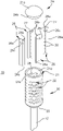
- FIG. 3 is an exploded fragmented perspective view of a head assembly in accordance with the embodiment depicted in FIG. 2 .
- FIG. 4 is an exploded cross-sectional view taken along line 4 - 4 in FIG. 2 of the head assembly.
- FIG. 5 is a top plan view of a guide in accordance with the embodiment of head assembly of FIG. 3 .
- top, bottom, front, back, right and left refer to the illustrated embodiment as oriented in the view being referred to.
- the words “upwardly” and “downwardly” refer to directions up or down and away from, respectively, the geometric center of the embodiment being described and designated parts thereof. Such terminology will include the words specifically mentioned, derivatives thereof and words of similar meaning.
- the embodiment of the improved nose trimmer 10 includes the elongated handle 12 extending downwardly from the head assembly 20 .
- the head assembly 20 generally has a cylindrical body with a cylindrical sidewall 21 extending between a lid 24 and a base 25 with a plurality of vents 22 spaced along the cylindrical sidewall 21 .
- the embodiment of the lid 24 depicted in FIG. 3 is generally illustrated as being mushroom-shaped with an upper convex portion 24 a adjoined to a lower cylindrical portion 24 b .
- the outer radius associated with the lower cylindrical portion 24 b is less than the outer radius associated with the upper convex portion 24 a .
- the outer radius of the lower cylindrical portion 24 b is generally less than the inner radius associated with the inner surface of the cylindrical body 23 .
- the lower cylindrical portion 24 b is generally configured for receipt within the circumferential sidewall 21 associated with the cylindrical body 23 .
- the upper convex portion 24 a provides a protective surface to limit injury along the nasal cavity during use.
- the upper convex portion 24 a has an outer radius generally greater than the outer radius of the circumferential sidewall 21 , thereby, limiting downward movement of the lid 24 .
- the improved nose trimmer 10 may be inserted into a nasal cavity (not shown). Once positioned, the nose trimmer 10 may be rotated clockwise and counter-clockwise presenting the vents 22 for receiving any nearby hair follicles (not shown). The interiorly located hair cutting surface then engages the received hair follicles for trimming as desired.
- FIG. 3 An exploded view of the head assembly 20 is depicted in FIG. 3 with the lid 24 extended from plural knives 26 which are extended outwardly from a cylindrical body 23 which includes the circumferential sidewall 21 extending between a proximate end 21 a and a distal end 21 b with the plurality of vents 22 spaced along the sidewall 21 .
- the radially extended plural knives 26 in alignment with the circumferential sidewall 21 present the hair cutting surface for engagement with any hair follicles (not shown) extended through vents 22 .
- FIG. 4 A cross-sectional view of the trimmer 10 is depicted in FIG. 4 with one of the knives 26 extended between an upper brace 28 and a lower brace 29 . While the embodiment illustrated in FIG. 4 includes both an upper and a lower brace 28 , 29 the vented hair trimmer 10 may include only one or more than two braces, also referred to herein as guides, to support the knives 26 .
- the upper and lower brace 28 , 29 circumscribe a central channel 32 and are configured for receiving and extending the plural knives 26 in alignment with the circumferential sidewall 21 .
- the central channel 32 extends from the elongated handle 12 , through the base 25 and into the cylindrical body 23 .
- the upper and lower brace 28 , 29 position at least one of the rays associated with the knives 26 along the central channel 32 .
- the embodiment of the upper and lower brace 28 , 29 depicted in FIG. 5 for example, guide the knives 26 as they extend radially from the central channel 32 towards an outer ring 33 .
- the upper and lower braces 28 , 29 maintain the knives 26 near the circumferential sidewall 21 during reciprocal operation.
- the upper and lower brace 28 , 29 have an outer dimension for extension of the outer ring 33 at least partially through one of the vents 22 and for placement of one of the cutting surfaces 26 a along the inner surface of the circumferential sidewall 21 .
- the embodiment of the upper and lower brace 28 , 29 may be configured for at least partial receipt by a pair of oppositely spaced vents 22 , supporting and spacing the braces 28 , 29 during use.
- An embodiment of the head assembly 20 includes the upper brace 28 and lower brace 29 .
- An embodiment of one of the braces 28 , 29 is illustrated in FIGS. 4-5 .
- exemplary brace 28 include four Y-projections 31 which extends from the circumferential sidewall 21 towards the central channel 32 .
- the central channel 32 generally extends along the central axis from the lid 24 , through the vented head assembly 20 to the handle 12 .
- the embodiment of the knives 26 illustrated in FIGS. 3-4 illustrates a star shape with three rays radiating outward from a node 27 .
- the rays associated with each of knives 26 includes a pair of cutting edges 26 a extending angularly from a tang 26 b .
- An embodiment of the tang 26 b includes a plurality of perforations 30 .
- the pair of cutting edges 26 a extend from the node 27 in generally opposite directions for abutting the inner circumferential sidewall 21 .
- the tang 26 b extends from each of the cutting edges 26 a in an opposite direction from the node 27 .
- each cutting edge 26 a extends angularly from the tang 26 b .
- the angular orientation of the pair of cutting edges 26 a and the tang 26 b presents a generally Y-shaped knife 26 with a major angle 26 c surrounded by a pair of inferior angles 26 d .
- the major angle 26 c is presented between the pair of cutting edges 26 a , opposite the tang 26 b .
- the major angle 26 c is generally as much as or greater than the inferior angles 26 d .
- the inferior angle 26 d is generally located between each cutting edge 26 a and the tang 26 b and adjacent to the major angle 26 c . As depicted, the inferior angles 26 d between each cutting edge 26 a and the tang 26 b are generally symmetrical, but may vary as desired.
- the perforated tang 26 b extends from the cutting edges 26 a towards the central channel 32 during receipt between a pair of adjacent Y-projections 31 .
- the knives 26 are allowed to reciprocate laterally and longitudinally as the trimmer 10 is manually operated for trimming any nearby hair follicles.
- the upper and lower braces 28 , 29 receive and position the knives 26 during reciprocal operation, from any received hair follicles for trimming.
- the alignment and positioning of the plural knives 26 by the guide 28 form a cutting assembly, also referred to as the hair shaping assembly.
- the embodiment of the vents 22 depicted in FIG. 2 , include arcuate ends 22 a separated by an elongated channel 22 b which is configured for the insertion of hair follicles through the elongated channel 22 b and the arcuate ends 22 a allow for receipt without inadvertently catching, gripping or ripping the follicles.
- the vents 22 may include an arcuate top surface 22 c.
Landscapes
- Life Sciences & Earth Sciences (AREA)
- Forests & Forestry (AREA)
- Engineering & Computer Science (AREA)
- Mechanical Engineering (AREA)
- Dry Shavers And Clippers (AREA)
Abstract
The present invention provides a reciprocally rotatable trimmer with a plurality of vents for removing nasal hair follicles, the vented nose trimmer including a head assembly and an elongated handle, the head assembly including a plurality of vents spaced along the head assembly for selectively trimming said nasal hair follicles.
Description
- The current invention relates in general to a nose hair trimmer and more specifically to a vented nose hair trimmer with a plurality of knives.
- Generally, there are two types of nose hair trimmers. Rotary nose hair trimmers and linear nose hair trimmers. A rotary nose hair trimmer uses a set of internally positioned rotary blades surrounded by a head housing the rotary blades for trimming nose hair. The head protects the nose from injury by maintaining the blades internally. A linear nose hair trimmer has movable blades, moving cooperatively with respect to a fixed blade, the blades being disposed in a head shaped for insertion into a nasal canal. Both the aforementioned types have difficulties in trimming typical nose hair in that they are very inefficient and provide limited cutting surfaces.
- Typical nose trimmers use an arrangement of blades which includes two opposing blades where at least part of each of cutting surfaces are in alignment. Typically, the blades have a plurality of teeth along at least one surface aligned with each other to create a scissoring action. In some cases, the scissor action causes ripping, tearing or pinching of the hair follicle which causes pain and possible injury in the user. Therefore, there is a need to provide a nose trimmer blade arrangement which is less likely to injure the user.
- In a typical nose trimmer, the length of the trimmed hair depends on the thickness of the blades. The spatial arrangement is necessary to reduce the likelihood of injury. In addition, the placement of the blades also determines the length of the trimmed hair and the smoothness of the trimming action. However, the ability to reduce the length of the trimmed hair using the traditional blade arrangement, can create a greater likelihood of injury to the user. It would thus be desirable to provide an improved nose hair trimmer which allowed for safer operation while providing for an improved trim.
- There is a need for an improved trimmer device which at least addresses some of the aforementioned disadvantages.
- In an embodiment of the present invention, the foregoing is addressed by providing a vented nose trimmer for selective trimming of nasal hair follicles, said vented nose trimmer comprising a head assembly supported by an elongated handle said head assembly further comprising a cylindrical body extending between a lid and a base said lid at least partially received within one end of said cylindrical body said base extending between said elongated handle and said cylindrical body a hair cutting surface; and a plurality of vents spaced along said head assembly, said vents being configured to provide access to the hair cutting surface for selectively trimming said nasal hair follicles.
- In general, the nasal hair trimmer is configured for being operated within a nasal cavity for trimming nasal hair follicles by reciprocally rotating the nasal hair trimmer causing the head assembly to rotate back and forth and up and down.
-
FIG. 1 is an environmental view of a nose trimmer at least partially received into a nasal cavity. -
FIG. 2 is a front perspective view of an embodiment of the nose trimmer in accordance with the embodiment depicted inFIG. 1 . -
FIG. 3 is an exploded fragmented perspective view of a head assembly in accordance with the embodiment depicted inFIG. 2 . -
FIG. 4 is an exploded cross-sectional view taken along line 4-4 inFIG. 2 of the head assembly. -
FIG. 5 is a top plan view of a guide in accordance with the embodiment of head assembly ofFIG. 3 . - Certain terminology will be used in the following description for convenience in reference only and will not be limiting. For example, top, bottom, front, back, right and left refer to the illustrated embodiment as oriented in the view being referred to. The words “upwardly” and “downwardly” refer to directions up or down and away from, respectively, the geometric center of the embodiment being described and designated parts thereof. Such terminology will include the words specifically mentioned, derivatives thereof and words of similar meaning.
- Referring to
FIG. 1 , an improved nose trimmer generally referred to byreference numeral 10 is illustrated as being received by an exemplarynasal cavity 2 associated with a user. The improvednose trimmer 10 generally includes anelongated handle 12 extending to a ventedhead assembly 20 which as depicted, is configured for receipt within a typical nasal cavity. - As further depicted in
FIG. 2 , the embodiment of the improvednose trimmer 10 includes theelongated handle 12 extending downwardly from thehead assembly 20. Thehead assembly 20, generally has a cylindrical body with acylindrical sidewall 21 extending between alid 24 and abase 25 with a plurality ofvents 22 spaced along thecylindrical sidewall 21. - The embodiment of the
lid 24 depicted inFIG. 3 is generally illustrated as being mushroom-shaped with an upperconvex portion 24 a adjoined to a lowercylindrical portion 24 b. The outer radius associated with the lowercylindrical portion 24 b is less than the outer radius associated with theupper convex portion 24 a. The outer radius of the lowercylindrical portion 24 b is generally less than the inner radius associated with the inner surface of thecylindrical body 23. As depicted inFIG. 4 , the lowercylindrical portion 24 b is generally configured for receipt within thecircumferential sidewall 21 associated with thecylindrical body 23. Theupper convex portion 24 a provides a protective surface to limit injury along the nasal cavity during use. In addition, theupper convex portion 24 a has an outer radius generally greater than the outer radius of thecircumferential sidewall 21, thereby, limiting downward movement of thelid 24. - During operation, the hair cutting surface (illustrated in
FIG. 4 ) is maintained internally within thehead assembly 20. Generally, thevents 22 provide intermitting access for the internal hair cutting surface to engage any received nasal hair follicles. As depicted inFIG. 2 , thevents 22 are vertically spaced along thecylindrical sidewall 21 of thehead assembly 20 and provide access to the hair cutting surface for trimming the desired nasal hair follicles (not shown). Generally, the hair cutting surface is located within thehead assembly 20 and faces thevents 22 for engagement with the hair follicles. The hair cutting surface generally includes the outwardly directed portion of theplural knives 26 and the inner surface of thecylindrical sidewall 21. During operation, the improvednose trimmer 10 may be inserted into a nasal cavity (not shown). Once positioned, thenose trimmer 10 may be rotated clockwise and counter-clockwise presenting thevents 22 for receiving any nearby hair follicles (not shown). The interiorly located hair cutting surface then engages the received hair follicles for trimming as desired. - An exploded view of the
head assembly 20 is depicted inFIG. 3 with thelid 24 extended fromplural knives 26 which are extended outwardly from acylindrical body 23 which includes thecircumferential sidewall 21 extending between aproximate end 21 a and adistal end 21 b with the plurality ofvents 22 spaced along thesidewall 21. The radially extendedplural knives 26 in alignment with thecircumferential sidewall 21 present the hair cutting surface for engagement with any hair follicles (not shown) extended throughvents 22. - A cross-sectional view of the
trimmer 10 is depicted inFIG. 4 with one of theknives 26 extended between anupper brace 28 and alower brace 29. While the embodiment illustrated inFIG. 4 includes both an upper and alower brace hair trimmer 10 may include only one or more than two braces, also referred to herein as guides, to support theknives 26. - Generally, the upper and
lower brace central channel 32 and are configured for receiving and extending theplural knives 26 in alignment with thecircumferential sidewall 21. Thecentral channel 32 extends from theelongated handle 12, through thebase 25 and into thecylindrical body 23. In general, the upper andlower brace knives 26 along thecentral channel 32. The embodiment of the upper andlower brace FIG. 5 , for example, guide theknives 26 as they extend radially from thecentral channel 32 towards anouter ring 33. In addition to positioning theknives 26 along thecentral channel 32, the upper andlower braces knives 26 near thecircumferential sidewall 21 during reciprocal operation. - As illustrated the upper and
lower brace outer ring 33 at least partially through one of thevents 22 and for placement of one of thecutting surfaces 26 a along the inner surface of thecircumferential sidewall 21. Optionally, the embodiment of the upper andlower brace vents 22, supporting and spacing thebraces - An embodiment of the
head assembly 20 includes theupper brace 28 andlower brace 29. An embodiment of one of thebraces FIGS. 4-5 . As illustrated,exemplary brace 28 include four Y-projections 31 which extends from thecircumferential sidewall 21 towards thecentral channel 32. Thecentral channel 32 generally extends along the central axis from thelid 24, through the ventedhead assembly 20 to thehandle 12. - The embodiment of the
knives 26 illustrated inFIGS. 3-4 illustrates a star shape with three rays radiating outward from anode 27. As depicted, the rays associated with each ofknives 26 includes a pair of cuttingedges 26 a extending angularly from atang 26 b. An embodiment of thetang 26 b includes a plurality ofperforations 30. - The pair of cutting
edges 26 a extend from thenode 27 in generally opposite directions for abutting the innercircumferential sidewall 21. Thetang 26 b extends from each of the cutting edges 26 a in an opposite direction from thenode 27. As depicted, each cuttingedge 26 a extends angularly from thetang 26 b. The angular orientation of the pair of cuttingedges 26 a and thetang 26 b presents a generally Y-shapedknife 26 with amajor angle 26 c surrounded by a pair ofinferior angles 26 d. Themajor angle 26 c is presented between the pair of cuttingedges 26 a, opposite thetang 26 b. Themajor angle 26 c is generally as much as or greater than theinferior angles 26 d. Theinferior angle 26 d is generally located between each cuttingedge 26 a and thetang 26 b and adjacent to themajor angle 26 c. As depicted, theinferior angles 26 d between each cuttingedge 26 a and thetang 26 b are generally symmetrical, but may vary as desired. - As illustrated, the
perforated tang 26 b extends from the cutting edges 26 a towards thecentral channel 32 during receipt between a pair of adjacent Y-projections 31. In receipt by the upper andlower braces knives 26 are allowed to reciprocate laterally and longitudinally as thetrimmer 10 is manually operated for trimming any nearby hair follicles. - In operation, the upper and
lower braces knives 26 during reciprocal operation, from any received hair follicles for trimming. Generally, the alignment and positioning of theplural knives 26 by theguide 28 form a cutting assembly, also referred to as the hair shaping assembly. The embodiment of thevents 22, depicted inFIG. 2 , include arcuate ends 22 a separated by an elongated channel 22 b which is configured for the insertion of hair follicles through the elongated channel 22 b and the arcuate ends 22 a allow for receipt without inadvertently catching, gripping or ripping the follicles. Optionally, as depicted inFIG. 4 , thevents 22 may include an arcuatetop surface 22 c. - It should be understood that while certain forms of this invention have been illustrated and described, it is not limited thereto except insofar as such limitations are included in the following claims.
Claims (9)
1. A vented nose trimmer for trimming hair follicles, said vented nose trimmer comprising:
a head supported by a handle;
said head further comprising a body extending between a top and a base and defining a cutting area;
said base extending between said handle and said cylindrical body;
a plurality of vents spaced along said head, at least one of said vents being configured to provide access said cutting area;
a cutting assembly received by said cutting area comprising at least one pair of guides in receipt of at least one knife;
said knife comprising a central node wherein said knife extends radially from said central node towards at least one of said vents; and
each of said pair of guides comprising a plurality of projections extending from one of said vents into the cutting area.
2. The vented nose trimmer of claim 1 wherein said knife includes a first cutting edge separated from a second cutting edge by a major angle.
3. The vented nose trimmer of claim 2 wherein said knife further comprises a tang extended outwardly from said first cutting edge and said second cutting edge at said central node.
4. The vented nose trimmer of claim 3 wherein said tang includes at least one perforation.
5. The vented nose trimmer of claim 1 , wherein said knife includes a plurality of rays extending from said central node.
6. The vented nose trimmer of claim 2 , wherein said first cutting edge and said second cutting edge extend radially from said central node.
7. The vented nose trimmer of claim 1 , wherein at least one guide from said pair of guides is Y-shaped.
8. (canceled)
9. (canceled)
Priority Applications (1)
| Application Number | Priority Date | Filing Date | Title |
|---|---|---|---|
| US17/534,575 US20220184828A1 (en) | 2020-12-15 | 2021-11-24 | Vented nose trimmer |
Applications Claiming Priority (2)
| Application Number | Priority Date | Filing Date | Title |
|---|---|---|---|
| US17/122,592 US11213961B1 (en) | 2020-12-15 | 2020-12-15 | Vented nose trimmer |
| US17/534,575 US20220184828A1 (en) | 2020-12-15 | 2021-11-24 | Vented nose trimmer |
Related Parent Applications (1)
| Application Number | Title | Priority Date | Filing Date |
|---|---|---|---|
| US17/122,592 Continuation US11213961B1 (en) | 2020-12-15 | 2020-12-15 | Vented nose trimmer |
Publications (1)
| Publication Number | Publication Date |
|---|---|
| US20220184828A1 true US20220184828A1 (en) | 2022-06-16 |
Family
ID=79169603
Family Applications (2)
| Application Number | Title | Priority Date | Filing Date |
|---|---|---|---|
| US17/122,592 Active US11213961B1 (en) | 2020-12-15 | 2020-12-15 | Vented nose trimmer |
| US17/534,575 Abandoned US20220184828A1 (en) | 2020-12-15 | 2021-11-24 | Vented nose trimmer |
Family Applications Before (1)
| Application Number | Title | Priority Date | Filing Date |
|---|---|---|---|
| US17/122,592 Active US11213961B1 (en) | 2020-12-15 | 2020-12-15 | Vented nose trimmer |
Country Status (1)
| Country | Link |
|---|---|
| US (2) | US11213961B1 (en) |
Families Citing this family (1)
| Publication number | Priority date | Publication date | Assignee | Title |
|---|---|---|---|---|
| DE202020005266U1 (en) * | 2020-12-22 | 2022-03-28 | Terry & Scott Unternehmergesellschaft (haftungsbeschränkt) | nose hair trimmer |
Citations (5)
| Publication number | Priority date | Publication date | Assignee | Title |
|---|---|---|---|---|
| US1229824A (en) * | 1915-03-11 | 1917-06-12 | Bernard Tewelow | Cutter for removing hair from cavities. |
| US2686965A (en) * | 1954-01-08 | 1954-08-24 | Burton J Limpan | Hair clipper |
| US3284894A (en) * | 1965-06-21 | 1966-11-15 | Joseph J Ryan | Razor having hair trimming means |
| US4571827A (en) * | 1984-10-17 | 1986-02-25 | Lee Chin Piao | Vibrissa cutters |
| US4958432A (en) * | 1989-10-26 | 1990-09-25 | Marshall Willie J | Rotary hair trimmer |
-
2020
- 2020-12-15 US US17/122,592 patent/US11213961B1/en active Active
-
2021
- 2021-11-24 US US17/534,575 patent/US20220184828A1/en not_active Abandoned
Patent Citations (5)
| Publication number | Priority date | Publication date | Assignee | Title |
|---|---|---|---|---|
| US1229824A (en) * | 1915-03-11 | 1917-06-12 | Bernard Tewelow | Cutter for removing hair from cavities. |
| US2686965A (en) * | 1954-01-08 | 1954-08-24 | Burton J Limpan | Hair clipper |
| US3284894A (en) * | 1965-06-21 | 1966-11-15 | Joseph J Ryan | Razor having hair trimming means |
| US4571827A (en) * | 1984-10-17 | 1986-02-25 | Lee Chin Piao | Vibrissa cutters |
| US4958432A (en) * | 1989-10-26 | 1990-09-25 | Marshall Willie J | Rotary hair trimmer |
Also Published As
| Publication number | Publication date |
|---|---|
| US11213961B1 (en) | 2022-01-04 |
Similar Documents
| Publication | Publication Date | Title |
|---|---|---|
| US8475241B1 (en) | Field dressing knife | |
| CA2254672C (en) | Attachment comb for hair clipper | |
| CN107735230B (en) | razor | |
| US20050055831A1 (en) | Manicuring appliance | |
| US11213961B1 (en) | Vented nose trimmer | |
| US20180319025A1 (en) | Scissors | |
| JP6339417B2 (en) | Rotary electric razor | |
| JP5950379B1 (en) | Plow scissors | |
| RU2697467C2 (en) | Beard trimming device with one or more rotary heads | |
| US5062210A (en) | Cactus thorn removing tool | |
| US10618187B2 (en) | Scissor guide | |
| US11778952B2 (en) | Shearing device providing a pair of pincers for securing the sheared object | |
| US20190240854A1 (en) | Hair cutting device | |
| ES2704710T3 (en) | Apparatus for cutting animal nails and procedures for using them | |
| CN215012564U (en) | Multi-hole pet nail clipper | |
| KR102303841B1 (en) | Cartilage acquisition device | |
| CN219741539U (en) | Nail clipper for pets | |
| CN214758024U (en) | Gardens are with multi-functional trimming means of nursery stock | |
| CN215395341U (en) | Safe vibrissa-cutting tweezers | |
| CN218278246U (en) | A cat nail trimming device | |
| US11338458B1 (en) | Combination bagel slicer and spreader | |
| US20210259157A1 (en) | Shearing device providing a pair of pincers for securing the sheared object | |
| KR200260239Y1 (en) | The finger nails cleaning of scissors | |
| CN116887962A (en) | Vibrissa cutter | |
| JP3048797U (en) | Hand tools for cutting |
Legal Events
| Date | Code | Title | Description |
|---|---|---|---|
| STPP | Information on status: patent application and granting procedure in general |
Free format text: DOCKETED NEW CASE - READY FOR EXAMINATION |
|
| STPP | Information on status: patent application and granting procedure in general |
Free format text: NON FINAL ACTION MAILED |
|
| STCB | Information on status: application discontinuation |
Free format text: ABANDONED -- FAILURE TO RESPOND TO AN OFFICE ACTION |