US20220184825A1 - Folding knife with selectively hidden blade release - Google Patents
Folding knife with selectively hidden blade release Download PDFInfo
- Publication number
- US20220184825A1 US20220184825A1 US17/550,557 US202117550557A US2022184825A1 US 20220184825 A1 US20220184825 A1 US 20220184825A1 US 202117550557 A US202117550557 A US 202117550557A US 2022184825 A1 US2022184825 A1 US 2022184825A1
- Authority
- US
- United States
- Prior art keywords
- blade
- knife
- release mechanism
- carrier
- blade carrier
- Prior art date
- Legal status (The legal status is an assumption and is not a legal conclusion. Google has not performed a legal analysis and makes no representation as to the accuracy of the status listed.)
- Granted
Links
Images


Classifications
-
- B—PERFORMING OPERATIONS; TRANSPORTING
- B26—HAND CUTTING TOOLS; CUTTING; SEVERING
- B26B—HAND-HELD CUTTING TOOLS NOT OTHERWISE PROVIDED FOR
- B26B1/00—Hand knives with adjustable blade; Pocket knives
- B26B1/02—Hand knives with adjustable blade; Pocket knives with pivoted blade
-
- B—PERFORMING OPERATIONS; TRANSPORTING
- B25—HAND TOOLS; PORTABLE POWER-DRIVEN TOOLS; MANIPULATORS
- B25G—HANDLES FOR HAND IMPLEMENTS
- B25G1/00—Handle constructions
- B25G1/08—Handle constructions with provision for storing tool elements
-
- B—PERFORMING OPERATIONS; TRANSPORTING
- B26—HAND CUTTING TOOLS; CUTTING; SEVERING
- B26B—HAND-HELD CUTTING TOOLS NOT OTHERWISE PROVIDED FOR
- B26B5/00—Hand knives with one or more detachable blades
Definitions
- This disclosure relates to folding knives that can selectively expose or protect a cutting edge of a replaceable blade.
- Certain conventional folding knifes configured with removable blades can include a blade release mechanism that allows the blade to be removed only when the blade carrier is positioned at a specific predetermined (for example, 45 degrees) angle from the top of the handle.
- a blade release mechanism that allows the blade to be removed only when the blade carrier is positioned at a specific predetermined (for example, 45 degrees) angle from the top of the handle.
- blade release mechanisms render it impossible for the user to engage the blade release mechanism while the knife is in the cutting position. Without an indication to a user that the user must position the blade carrier at the specific predetermined angle from the top of the handle before attempting to release the blade, a user might mistakenly believe that the blade release mechanism is broken when he/she is unable to engage the blade release mechanism when the utility knife is in the cutting position.
- FIG. 1 depicts a side view of an example folding knife in accordance with one or more embodiments of the disclosure.
- FIG. 2 depicts a side view of the example folding knife of FIG. 1 in accordance with one or more embodiments of the disclosure.
- FIG. 3 depicts a side view of an example blade carrier of the example folding knife of FIG. 1 in accordance with one or more embodiments of the disclosure.
- FIG. 4 depicts an exploded view of the example blade carrier of FIG. 3 in accordance with one or more embodiments of the disclosure.
- FIG. 5 depicts a side view of the example blade carrier of FIG. 3 in accordance with one or more embodiments of the disclosure.
- FIG. 6 depicts a side view of the example blade carrier of FIG. 3 in accordance with one or more embodiments of the disclosure.
- FIG. 7 depicts a side view of an example folding knife in accordance with one or more embodiments of the disclosure.
- FIG. 8 depicts a side view of the example folding knife of FIG. 7 in accordance with one or more embodiments of the disclosure.
- FIG. 9 depicts an exploded view of an example blade carrier of the example folding knife of FIG. 7 in accordance with one or more embodiments of the disclosure.
- FIG. 10 depicts a side view of an example blade carrier of FIG. 9 in accordance with one or more embodiments of the disclosure.
- FIG. 11 depicts a side view of an example folding knife in accordance with one or more embodiments of the disclosure.
- FIG. 12 depicts a side view of the example folding knife of FIG. 11 in accordance with one or more embodiments of the disclosure.
- FIG. 13 depicts an exploded view of an example blade carrier of the example folding knife of FIG. 11 in accordance with one or more embodiments of the disclosure.
- FIG. 14 depicts a side view of the example blade carrier of FIG. 13 in accordance with one or more embodiments of the disclosure.
- FIG. 15 depicts an example process for removing a knife blade from an example folding knife in accordance with one or more embodiments of the disclosure.
- FIG. 16 depicts an exploded view of an example folding knife in accordance with one or more embodiments of the disclosure.
- FIG. 17 depicts an example process for storing a knife blade in a blade storage mechanism of an example folding knife in accordance with one or more embodiments of the disclosure.
- folding knives that can selectively expose or protect a cutting edge of a replaceable blade. Further, certain embodiments of the disclosure can include folding knives that can intrinsically communicate to a user a specified position for the blade carrier relative to the handle in order to permit a blade change operation. It may be appreciated that other aspects of certain embodiments of the disclosure may include preventing inadvertent access to the blade change actuator when the knife is in the cutting position. Further, in order to make the blade release mechanism more intuitive to users, in one embodiment, the blade release mechanism may be impossible to actuate while the knife is in the cutting position, and the blade release mechanism may be entirely inaccessible while the knife is in the cutting position. More specifically, the button to release the blade may be at least partially hidden while the knife is in the cutting position. Only as the blade carrier is positioned at a certain angle from the knife handle is the button of the blade release mechanism made visible and accessible.
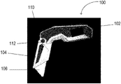
- FIG. 1 depicts a side view of an example folding knife 100 in accordance with one or more example embodiments of the disclosure.
- the folding knife 100 may include a handle 102 , a blade carrier 104 , and a blade 106 .
- the blade carrier 104 may be configured to be mounted to the handle 102 .
- the blade carrier 104 may be configured to receive the blade 106 .
- the handle 102 may include a slot for receiving the blade carrier 104 .
- the handle 102 and the blade carrier 104 may be made of a rigid material.
- the blade carrier 104 may be configured to rotate about an axis 108 such that the blade 106 may rotate parallel to the handle 102 . Further, the axis 108 may be located where the blade carrier 104 is mounted to the handle 102 .
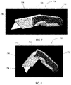
- FIG. 2 depicts a side view of the example folding knife 100 of FIG. 1 in accordance with one or more example embodiments of the disclosure.
- the folding knife 100 may be configured such that the blade carrier 104 is able to rotate until it reaches a specific predetermined angle from the handle 102 .
- the specific predetermined angle may be 45 degrees.
- the folding knife 100 may be in a blade release position.
- a blade release mechanism 110 which may be built into the blade carrier 104 , may become exposed to a user when the blade carrier 104 is in the blade release position.
- FIG. 2 depicts a side view of the example folding knife 100 of FIG. 1 in accordance with one or more example embodiments of the disclosure.
- the folding knife 100 may be configured such that the blade carrier 104 is able to rotate until it reaches a specific predetermined angle from the handle 102 .
- the specific predetermined angle may be 45 degrees.
- the folding knife 100 may be in a blade release position.
- a blade release mechanism 110 which may be built into the blade carrier
- the blade release mechanism 110 may include an actuator 112 , for example, a button.
- the actuator 112 may be entirely exposed when the blade carrier 104 is in the blade release position. In other embodiments, the actuator 112 may be partially exposed when the blade carrier 104 is in the blade release position. Thus, in some embodiments, the actuator 112 may be partially obscured from view when the folding knife 100 is not in the blade release position.
- FIG. 3 depicts a side view of a blade carrier 104 of the example folding knife 100 in accordance with one or more example embodiments of the disclosure.
- Blade carrier 104 may include blade release mechanism 110 having an actuator 112 .
- the actuator 112 may be a button 112 a.
- FIG. 4 depicts an exploded view of the blade carrier 104 of the example folding knife 100 in accordance with one or more example embodiments of the disclosure.
- the blade carrier 104 may be made of multiple components mounted to each other.
- the blade carrier 104 may include a left cap 114 , a right cap 116 , a compression spring 118 , and a lift bar 120 .
- the left cap 114 and the right cap 116 may fit together to contain the blade 106 .
- the left cap 114 and the right cap 116 may be mounted together by means of the compression spring 118 and the lift bar 120 , both of which may be mounted to either of the left cap 114 or the right cap 116 .
- the compression spring 118 and the lift bar 120 may rest inside of the left cap 114 and the right cap 116 .
- functional equivalents to the left cap 114 , the right cap 116 , the compression spring 118 , and the lift bar 120 may likewise be understood as being utilized in various alternative embodiments.
- the lift bar 120 may include an extruded piece of material to hold the blade 106 in place, a cylindrical peg that acts as a pivot point, and an extruded button feature, for example, button 112 a depicted in FIG. 3 .
- the compression spring 118 may sit partially inside of a hollow button, for example, button 112 a depicted in FIG. 3 , and partially in a pocket of either the left cap 114 or the right cap 116 .
- FIG. 5 depicts a side view of the blade carrier 104 in accordance with one or more example embodiments of the disclosure.
- the blade release mechanism 110 may be used to release the blade 106 .
- the button 112 a moves inwards and towards the left cap 114 and the right cap 116 .
- This causes a first end of the lift bar 120 to move towards the left cap 114 and the right cap 116 .
- the lift bar 120 then rotates about the cylindrical peg that acts as a pivot point—and a second distal end of the lift bar 120 is forced outwards and away from the left cap 114 and the right cap 116 .
- the second distal end of the lift bar 120 may thus move in a direction opposite to the direction in which the user pushed the button 112 a . As this motion occurs, the lift bar 120 disengages from the blade 106 , thus enabling a user to remove the blade 106 from the blade carrier 104 .
- FIG. 6 depicts a side view of blade carrier 104 in accordance with one or more example embodiments of the disclosure.
- the blade release mechanism 110 may be used to re-engage the blade 106 .
- the compression spring 118 which may be partially sitting inside a hollow of button 112 a and extending towards a wall of the left cap 114 or the right cap 116 , may no longer be in compression and may expand. This expansion of the compression spring 118 forces a first end of the lift bar 120 to move away from the left cap 114 and the right cap 116 .
- the lift bar 120 then rotates about the cylindrical peg that acts as a pivot point, and a second distal end of the lift bar 120 is forced inwards and towards the left cap 114 and the right cap 116 , until the lift bar 120 is in contact with both the left cap 114 and the right cap 116 .
- the blade 106 if the blade 106 is disposed within the blade carrier 104 , the blade 106 will be secured by the compression spring 118 acting on the lift bar 120 to force the left cap 114 and the right cap 116 towards each other.
- the left cap 114 , the right cap 116 , and the lift bar 120 may be formed from cast aluminum or zinc or powdered metal stainless components.
- the lift bar 120 may be made of stainless steel sheet metal or an engineering plastic such as ABS, polypropylene, or any other strong and/or durable grade of plastic.
- the compression spring 118 may be made of either stainless steel or a plated music wire grade of steel.
- FIG. 7 depicts a side view of an example folding knife 700 in accordance with one or more example embodiments of the disclosure.
- the folding knife 700 may include a handle 702 , a blade carrier 704 , and a blade 706 .
- the blade carrier 704 may be configured to be mounted to the handle 702 .
- the blade carrier 704 may be configured to receive the blade 706 .
- the handle 702 may include a slot for receiving the blade carrier 704 .
- the handle 702 and the blade carrier 704 may be made of a rigid material.
- the blade carrier 704 may be configured to rotate about an axis 708 such that the blade 706 may rotate parallel to the handle 702 . Further, the axis 708 may be located where the blade carrier 704 is mounted to the handle 702 .
- FIG. 8 depicts a side view of the example folding knife 700 of FIG. 7 in accordance with one or more example embodiments of the disclosure.
- the folding knife 700 may be configured such that the blade carrier 704 is able to rotate until it reaches a specific predetermined angle from the handle 702 .
- the specific predetermined angle may be 45 degrees.
- the folding knife 700 may be in a blade release position.
- a blade release mechanism 710 which may be built into the blade carrier 704 , may become exposed to a user when the blade carrier 704 is in the blade release position.
- FIG. 8 depicts a blade release mechanism 710 , which may be built into the blade carrier 704 , may become exposed to a user when the blade carrier 704 is in the blade release position.
- the blade release mechanism 710 may include an actuator 712 , for example, a slide bar 720 .
- an actuator 712 for example, a slide bar 720 .
- a portion of the actuator 712 may be entirely exposed when the blade carrier 704 is in the blade release position. In other embodiments, a portion of the actuator 712 may be partially exposed when the blade carrier 704 is in the blade release position.
- FIG. 9 depicts an exploded view of the blade carrier 704 of the example folding knife 700 in accordance with one or more example embodiments of the disclosure.
- the blade carrier 704 may be made of multiple components mounted to each other.
- the blade carrier 704 may include a left cap 714 , a right cap 716 , a leaf spring 718 , and the slide bar 720 .
- the left cap 714 and the right cap 716 may fit together to contain the blade 706 .
- the left cap 714 and the right cap 716 may be mounted together by means of the leaf spring 718 and the slide bar 720 , both of which may be mounted to either of the left cap 714 or the right cap 716 .
- the leaf spring 718 and the slide bar 720 may rest inside of the left cap 714 and the right cap 716 .
- functional equivalents to the left cap 714 , the right cap 716 , the leaf spring 718 , and the slide bar 720 may likewise be understood as being utilized in various alternative embodiments.
- the slide bar 720 may include an extruded piece of material to assist the leaf spring 718 in holding the blade 706 in place.
- the leaf spring 718 may be in contact with the slide bar 720 , and the leaf spring 718 may sit partially in a pocket of either the left cap 714 or the right cap 716 .
- the leaf spring 718 is U-shaped.
- the left cap 714 and the right cap 716 may include a cut-out area at a first end to facilitate the back button 712 a being disposed proximate to the first end of the left cap 714 and the right cap 716 .
- FIG. 10 depicts a side view of the blade carrier 704 in accordance with one or more example embodiments of the disclosure.
- the blade release mechanism 710 may be used to release the blade 706 .
- the slide bar 720 moves inwards and towards the left cap 714 and the right cap 716 . This causes a first end of the slide bar 720 to come into contact with the leaf spring 718 .
- the leaf spring 718 may be used to hold the blade 706 in place within the blade carrier 704 until the leaf spring 718 is engaged by the slide bar 720 .
- the leaf spring 718 may be forced upwards by a second distal end of the slide bar 720 as the slide bar 720 is pushed inwards, thus enabling the blade 706 to be removed from the blade carrier 704 .
- the blade release mechanism 710 may be further used to re-engage the blade 706 .
- the leaf spring 718 may no longer be in compression and may expand. This expansion of the leaf spring 718 forces the distal second end of the slide bar 720 to move outwards and away from the left cap 714 and the right cap 716 .
- the blade 706 will be secured by the leaf spring 718 .
- the left cap 714 , the right cap 716 , and the slide bar 720 may be formed from cast aluminum or zinc or powdered metal stainless components.
- the slide bar 720 may be made of stainless steel sheet metal or an engineering plastic such as ABS, polypropylene, or any other strong and/or durable grade of plastic.
- the leaf spring 718 may be made of either stainless steel or a plated music wire grade of steel.
- FIG. 11 depicts a side view of an example folding knife 1100 in accordance with one or more example embodiments of the disclosure.
- the folding knife 1100 may include a handle 1102 , a blade carrier 1104 , and a blade 1106 .
- the blade carrier 1104 may be configured to be mounted to the handle 1102 .
- the blade carrier 1104 may be configured to receive the blade 1106 .
- the handle 1102 may include a slot for receiving the blade carrier 1104 .
- the handle 1102 and the blade carrier 1104 may be made of a rigid material.
- the blade carrier 1104 may be configured to rotate about an axis 1108 such that the blade 1106 may rotate parallel to the handle 1102 . Further, the axis 1108 may be located where the blade carrier 1104 is mounted to the handle 1102 .
- FIG. 12 depicts a side view of the example folding knife 1100 of FIG. 11 in accordance with one or more example embodiments of the disclosure.
- the folding knife 1100 may be configured such that the blade carrier 1104 is able to rotate until it reaches a specific predetermined angle from the handle 1102 .
- the specific predetermined angle may be 45 degrees.
- the folding knife 1100 may be in a blade release position.
- a blade release mechanism 1110 which may be built into the blade carrier 1104 , may become exposed to a user when the blade carrier 1104 is in the blade release position.
- the blade release mechanism 1110 may include an actuator 1112 , for example, a lift bar 1120 .
- the actuator 1112 may be entirely exposed when the blade carrier 1104 is in the blade release position. In other embodiments, the actuator 1112 may be partially exposed when the blade carrier 1104 is in the blade release position.
- FIG. 13 depicts an exploded view of the blade carrier 1104 of the example folding knife 1100 in accordance with one or more example embodiments of the disclosure.
- the blade carrier 1104 may be made of multiple components mounted to each other.
- the blade carrier 1104 may include a left cap 1114 , a right cap 1116 , a compression spring 1118 , a lift bar 1120 , and a wheel 1122 .
- the left cap 1114 and the right cap 1116 may fit together to contain the blade 1106 .
- the left cap 1114 and the right cap 1116 may be mounted together by means of the compression spring 1118 , the lift bar 1120 , and the wheel 1122 , all of which may be mounted to either of the left cap 1114 or the right cap 1116 .
- the compression spring 1118 , the lift bar 1120 , and the wheel 1122 may rest inside of the left cap 1114 and the right cap 1116 .
- functional equivalents to the left cap 1114 , the right cap 1116 , the compression spring 1118 , the lift bar 120 , and the wheel 1122 may likewise be understood as being utilized in various alternative embodiments.
- the lift bar 1120 may include an extruded piece of material to hold the blade 1106 in place and may be configured to rotate about a pivot point.
- the compression spring 1118 may sit partially in a pocket of either the left cap 1114 or the right cap 1116 .
- the wheel 1122 may be mounted to a back end of the left cap 1114 and the right cap 1116 .
- FIG. 14 depicts a side view of the blade carrier 1104 in accordance with one or more example embodiments of the disclosure.
- the blade release mechanism 1110 may be used to release the blade 1106 .
- the wheel 1122 turns counter-clockwise to engage with the lift bar 1120 .
- a tab on a first end of the lift bar 1120 may be configured to move downwards to come into contact with the compression spring 1118 .
- the compression spring 1118 may be compressed.
- the blade release mechanism 1110 may be used to re-engage the blade 1106 .
- the compression spring 1118 may no longer be in compression and may expand. This expansion of the compression spring 1118 then forces a first end of the lift bar 1120 to move upwards.
- the lift bar 120 then rotates about the pivot point, and a second distal end of the lift bar 1120 is forced downwards until the lift bar 1120 is in contact with the blade 1106 .
- the blade 1106 will be secured by the lift bar 1120 .
- the left cap 1114 , the right cap 1116 , the lift bar 1120 , and the wheel 1122 may be formed from cast aluminum or zinc or powdered metal stainless components.
- the lift bar 1120 may be made of stainless steel sheet metal or an engineering plastic such as ABS, polypropylene, or any other strong and/or durable grade of plastic.
- the compression spring 1118 may be made of either stainless steel or a plated music wire grade of steel.
- FIG. 15 depicts an example process for removing a knife blade 1506 from an example folding knife 1500 in accordance with one or more embodiments of the disclosure.
- the folding knife 1500 may be disposed in a cutting position.
- the folding knife 1500 may be rotated into a blade release position.
- a blade carrier 1504 of the folding knife may be rotated 45 degrees.
- a button 1512 on the blade carrier 1504 may be pushed.
- the button 1512 comes into contact with a first end of a lift bar 1520 , pushing the first end of the lift bar 1520 towards the blade carrier 1504 .
- the lift bar 1520 is caused to rotate about a pivot point, thus resulting in a second distal end of the lift bar 1520 being moved away from the blade 1506 .
- the button 1512 may be a portion of the lift bar 1520 .
- the portion of the lift bar 1520 that may be depressible may be of a different color than the rest of the lift bar 1520 so as to enable a user to quickly notice the portion of the lift bar 1520 that is depressible.
- a portion of the blade release mechanism 1510 that may be pushed or depressed to cause the release of the blade 1506 may be of a different color than the rest of the blade release mechanism 1510 so as to enable a user to quickly detect the correct button for blade release.
- the blade 1506 may be released.
- FIG. 16 depicts an exploded view of an example folding knife 1600 in accordance with one or more embodiments of the disclosure.
- An example folding knife 1600 may include a bottom casting, a bottom grip, a top casting, a top grip, a pivot, a push button 1612 , a bottom blade housing 1614 , a top blade housing 1616 , a lever 1620 , a holder screw, a first flat washer, a second flat washer, a leaf spring 1618 , a holder spring, a wire belt clip, a case screw, a door spring plate, a button spring, a pivot screw, a spring plate, and a belt clip screw.
- FIG. 17 depicts an example process for storing a knife blade 1706 in a blade storage mechanism 1724 of an example folding knife 1700 in accordance with one or more embodiments of the disclosure.
- a handle 1702 of the folding knife 1700 may further include a foldable blade storage mechanism 1724 that may be rotatable about a first end of the handle 1702 .
- the foldable blade storage mechanism 1724 may be configured to rotate about a pivot point at the first end of the handle 1702 .
- the blade storage mechanism 1724 may be in an open position if it has been rotated out of the handle 1702 .
- the blade storage mechanism 1724 may be in a closed position if it has been rotated back in to the handle 1702 .
- the blade storage mechanism 1724 may thus be sized and shaped to fit into the handle 1702 if a portion of the handle 1702 has been hollowed out.
- the blade storage mechanism 1724 may further be sized and shaped to store the knife blade 1706 , and may include a slot or a pocket for storing the knife blade 1706 .
- the blade storage mechanism 1724 thus provides a convenient solution for storing the knife blade 1706 when the knife blade 1706 is removed from blade carrier 1704 and for retrieving the knife blade 1706 when a user wishes to load the blade carrier 1704 .
Landscapes
- Engineering & Computer Science (AREA)
- Mechanical Engineering (AREA)
- Life Sciences & Earth Sciences (AREA)
- Forests & Forestry (AREA)
- Surgical Instruments (AREA)
- Knives (AREA)
Abstract
Description
- The present application claims priority to U.S. Ser. No. 63/125,963, filed Dec. 15, 2020, the contents of which are incorporated by reference.
- This disclosure relates to folding knives that can selectively expose or protect a cutting edge of a replaceable blade.
- Certain conventional folding knifes configured with removable blades can include a blade release mechanism that allows the blade to be removed only when the blade carrier is positioned at a specific predetermined (for example, 45 degrees) angle from the top of the handle. However, such blade release mechanisms render it impossible for the user to engage the blade release mechanism while the knife is in the cutting position. Without an indication to a user that the user must position the blade carrier at the specific predetermined angle from the top of the handle before attempting to release the blade, a user might mistakenly believe that the blade release mechanism is broken when he/she is unable to engage the blade release mechanism when the utility knife is in the cutting position.
- Various aspects of embodiments of the disclosure are provided herein, as well as certain associated methods of operation and functions of the related elements of structure and the combination of parts and economies of manufacture, will become more apparent upon consideration of the following description with reference to the accompanying drawings, all of which form a part of this specification, wherein like reference numerals designate corresponding parts in the various figures. In one embodiment of the disclosure, the structural components illustrated herein are drawn to scale. It is to be expressly understood, however, that the drawings are for the purpose of illustration and description only and are not intended as a definition of the limits of the disclosure, and that other scales and proportions are also contemplated and covered by this application. In addition, it should be appreciated that structural features shown or described in any one embodiment herein can be used in other embodiments as well. As used in the specification, the singular form of “a”, “an”, and “the” include plural referents unless the context clearly dictates otherwise.
- The detailed description is set forth with reference to the accompanying drawings. The use of the same reference numerals may indicate similar or identical items. Various embodiments may utilize elements and/or components other than those illustrated in the drawings, and some elements and/or components may not be present in various embodiments. Elements and/or components in the figures are not necessarily drawn to scale. Throughout this disclosure, depending on the context, singular and plural terminology may be used interchangeably.
-
FIG. 1 depicts a side view of an example folding knife in accordance with one or more embodiments of the disclosure. -
FIG. 2 depicts a side view of the example folding knife ofFIG. 1 in accordance with one or more embodiments of the disclosure. -
FIG. 3 depicts a side view of an example blade carrier of the example folding knife ofFIG. 1 in accordance with one or more embodiments of the disclosure. -
FIG. 4 depicts an exploded view of the example blade carrier ofFIG. 3 in accordance with one or more embodiments of the disclosure. -
FIG. 5 depicts a side view of the example blade carrier ofFIG. 3 in accordance with one or more embodiments of the disclosure. -
FIG. 6 depicts a side view of the example blade carrier ofFIG. 3 in accordance with one or more embodiments of the disclosure. -
FIG. 7 depicts a side view of an example folding knife in accordance with one or more embodiments of the disclosure. -
FIG. 8 depicts a side view of the example folding knife ofFIG. 7 in accordance with one or more embodiments of the disclosure. -
FIG. 9 depicts an exploded view of an example blade carrier of the example folding knife ofFIG. 7 in accordance with one or more embodiments of the disclosure. -
FIG. 10 depicts a side view of an example blade carrier ofFIG. 9 in accordance with one or more embodiments of the disclosure. -
FIG. 11 depicts a side view of an example folding knife in accordance with one or more embodiments of the disclosure. -
FIG. 12 depicts a side view of the example folding knife ofFIG. 11 in accordance with one or more embodiments of the disclosure. -
FIG. 13 depicts an exploded view of an example blade carrier of the example folding knife ofFIG. 11 in accordance with one or more embodiments of the disclosure. -
FIG. 14 depicts a side view of the example blade carrier ofFIG. 13 in accordance with one or more embodiments of the disclosure. -
FIG. 15 depicts an example process for removing a knife blade from an example folding knife in accordance with one or more embodiments of the disclosure. -
FIG. 16 depicts an exploded view of an example folding knife in accordance with one or more embodiments of the disclosure. -
FIG. 17 depicts an example process for storing a knife blade in a blade storage mechanism of an example folding knife in accordance with one or more embodiments of the disclosure. - Disclosed herein are folding knives that can selectively expose or protect a cutting edge of a replaceable blade. Further, certain embodiments of the disclosure can include folding knives that can intrinsically communicate to a user a specified position for the blade carrier relative to the handle in order to permit a blade change operation. It may be appreciated that other aspects of certain embodiments of the disclosure may include preventing inadvertent access to the blade change actuator when the knife is in the cutting position. Further, in order to make the blade release mechanism more intuitive to users, in one embodiment, the blade release mechanism may be impossible to actuate while the knife is in the cutting position, and the blade release mechanism may be entirely inaccessible while the knife is in the cutting position. More specifically, the button to release the blade may be at least partially hidden while the knife is in the cutting position. Only as the blade carrier is positioned at a certain angle from the knife handle is the button of the blade release mechanism made visible and accessible.
-
FIG. 1 depicts a side view of an example foldingknife 100 in accordance with one or more example embodiments of the disclosure. Thefolding knife 100 may include ahandle 102, ablade carrier 104, and ablade 106. As depicted inFIG. 1 , theblade carrier 104 may be configured to be mounted to thehandle 102. Theblade carrier 104 may be configured to receive theblade 106. In one embodiment, thehandle 102 may include a slot for receiving theblade carrier 104. Thehandle 102 and theblade carrier 104 may be made of a rigid material. As depicted inFIG. 1 , theblade carrier 104 may be configured to rotate about anaxis 108 such that theblade 106 may rotate parallel to thehandle 102. Further, theaxis 108 may be located where theblade carrier 104 is mounted to thehandle 102. -
FIG. 2 depicts a side view of the example foldingknife 100 ofFIG. 1 in accordance with one or more example embodiments of the disclosure. As depicted inFIG. 2 , thefolding knife 100 may be configured such that theblade carrier 104 is able to rotate until it reaches a specific predetermined angle from thehandle 102. In some embodiments, the specific predetermined angle may be 45 degrees. In some embodiments, when theblade carrier 104 is rotated by the specific predetermined angle, thefolding knife 100 may be in a blade release position. As depicted inFIG. 2 , ablade release mechanism 110, which may be built into theblade carrier 104, may become exposed to a user when theblade carrier 104 is in the blade release position. In some embodiments, as depicted inFIG. 2 , theblade release mechanism 110 may include anactuator 112, for example, a button. In some embodiments, as depicted inFIG. 2 , theactuator 112 may be entirely exposed when theblade carrier 104 is in the blade release position. In other embodiments, theactuator 112 may be partially exposed when theblade carrier 104 is in the blade release position. Thus, in some embodiments, theactuator 112 may be partially obscured from view when thefolding knife 100 is not in the blade release position. -
FIG. 3 depicts a side view of ablade carrier 104 of the example foldingknife 100 in accordance with one or more example embodiments of the disclosure.Blade carrier 104 may includeblade release mechanism 110 having anactuator 112. In one embodiment, theactuator 112 may be abutton 112 a. -
FIG. 4 depicts an exploded view of theblade carrier 104 of theexample folding knife 100 in accordance with one or more example embodiments of the disclosure. Theblade carrier 104 may be made of multiple components mounted to each other. In one embodiment, theblade carrier 104 may include aleft cap 114, aright cap 116, acompression spring 118, and alift bar 120. Theleft cap 114 and theright cap 116 may fit together to contain theblade 106. Theleft cap 114 and theright cap 116 may be mounted together by means of thecompression spring 118 and thelift bar 120, both of which may be mounted to either of theleft cap 114 or theright cap 116. Thecompression spring 118 and thelift bar 120 may rest inside of theleft cap 114 and theright cap 116. In other embodiments, functional equivalents to theleft cap 114, theright cap 116, thecompression spring 118, and thelift bar 120 may likewise be understood as being utilized in various alternative embodiments. - In some embodiments, the
lift bar 120 may include an extruded piece of material to hold theblade 106 in place, a cylindrical peg that acts as a pivot point, and an extruded button feature, for example,button 112 a depicted inFIG. 3 . In some embodiments, thecompression spring 118 may sit partially inside of a hollow button, for example,button 112 a depicted inFIG. 3 , and partially in a pocket of either theleft cap 114 or theright cap 116. -
FIG. 5 depicts a side view of theblade carrier 104 in accordance with one or more example embodiments of the disclosure. As depicted inFIG. 5 , theblade release mechanism 110 may be used to release theblade 106. As a user presses down on thebutton 112 a, thebutton 112 a moves inwards and towards theleft cap 114 and theright cap 116. This causes a first end of thelift bar 120 to move towards theleft cap 114 and theright cap 116. Thelift bar 120 then rotates about the cylindrical peg that acts as a pivot point—and a second distal end of thelift bar 120 is forced outwards and away from theleft cap 114 and theright cap 116. The second distal end of thelift bar 120 may thus move in a direction opposite to the direction in which the user pushed thebutton 112 a. As this motion occurs, thelift bar 120 disengages from theblade 106, thus enabling a user to remove theblade 106 from theblade carrier 104. -
FIG. 6 depicts a side view ofblade carrier 104 in accordance with one or more example embodiments of the disclosure. As depicted inFIG. 6 , theblade release mechanism 110 may be used to re-engage theblade 106. As a user releases all contact with thebutton 112 a and thelift bar 120, thecompression spring 118, which may be partially sitting inside a hollow ofbutton 112 a and extending towards a wall of theleft cap 114 or theright cap 116, may no longer be in compression and may expand. This expansion of thecompression spring 118 forces a first end of thelift bar 120 to move away from theleft cap 114 and theright cap 116. Thelift bar 120 then rotates about the cylindrical peg that acts as a pivot point, and a second distal end of thelift bar 120 is forced inwards and towards theleft cap 114 and theright cap 116, until thelift bar 120 is in contact with both theleft cap 114 and theright cap 116. At this point, if theblade 106 is disposed within theblade carrier 104, theblade 106 will be secured by thecompression spring 118 acting on thelift bar 120 to force theleft cap 114 and theright cap 116 towards each other. - In various embodiments, the
left cap 114, theright cap 116, and thelift bar 120 may be formed from cast aluminum or zinc or powdered metal stainless components. In some embodiments, thelift bar 120 may be made of stainless steel sheet metal or an engineering plastic such as ABS, polypropylene, or any other strong and/or durable grade of plastic. In some embodiments, thecompression spring 118 may be made of either stainless steel or a plated music wire grade of steel. -
FIG. 7 depicts a side view of anexample folding knife 700 in accordance with one or more example embodiments of the disclosure. Thefolding knife 700 may include ahandle 702, ablade carrier 704, and ablade 706. As depicted inFIG. 7 , theblade carrier 704 may be configured to be mounted to thehandle 702. Theblade carrier 704 may be configured to receive theblade 706. In one embodiment, thehandle 702 may include a slot for receiving theblade carrier 704. Thehandle 702 and theblade carrier 704 may be made of a rigid material. As depicted inFIG. 7 , theblade carrier 704 may be configured to rotate about anaxis 708 such that theblade 706 may rotate parallel to thehandle 702. Further, theaxis 708 may be located where theblade carrier 704 is mounted to thehandle 702. -
FIG. 8 depicts a side view of theexample folding knife 700 ofFIG. 7 in accordance with one or more example embodiments of the disclosure. As depicted inFIG. 7 , thefolding knife 700 may be configured such that theblade carrier 704 is able to rotate until it reaches a specific predetermined angle from thehandle 702. In some embodiments, the specific predetermined angle may be 45 degrees. In some embodiments, when theblade carrier 704 is rotated by the specific predetermined angle, thefolding knife 700 may be in a blade release position. As depicted inFIG. 8 , ablade release mechanism 710, which may be built into theblade carrier 704, may become exposed to a user when theblade carrier 704 is in the blade release position. In some embodiments, as depicted inFIG. 8 , theblade release mechanism 710 may include anactuator 712, for example, aslide bar 720. In some embodiments, as depicted inFIG. 8 , a portion of theactuator 712 may be entirely exposed when theblade carrier 704 is in the blade release position. In other embodiments, a portion of theactuator 712 may be partially exposed when theblade carrier 704 is in the blade release position. -
FIG. 9 depicts an exploded view of theblade carrier 704 of theexample folding knife 700 in accordance with one or more example embodiments of the disclosure. Theblade carrier 704 may be made of multiple components mounted to each other. In one embodiment, theblade carrier 704 may include aleft cap 714, aright cap 716, aleaf spring 718, and theslide bar 720. Theleft cap 714 and theright cap 716 may fit together to contain theblade 706. Theleft cap 714 and theright cap 716 may be mounted together by means of theleaf spring 718 and theslide bar 720, both of which may be mounted to either of theleft cap 714 or theright cap 716. Theleaf spring 718 and theslide bar 720 may rest inside of theleft cap 714 and theright cap 716. In other embodiments, functional equivalents to theleft cap 714, theright cap 716, theleaf spring 718, and theslide bar 720 may likewise be understood as being utilized in various alternative embodiments. - In some embodiments, the
slide bar 720 may include an extruded piece of material to assist theleaf spring 718 in holding theblade 706 in place. In some embodiments, theleaf spring 718 may be in contact with theslide bar 720, and theleaf spring 718 may sit partially in a pocket of either theleft cap 714 or theright cap 716. In some embodiments, theleaf spring 718 is U-shaped. In some embodiments, theleft cap 714 and theright cap 716 may include a cut-out area at a first end to facilitate the back button 712 a being disposed proximate to the first end of theleft cap 714 and theright cap 716. -
FIG. 10 depicts a side view of theblade carrier 704 in accordance with one or more example embodiments of the disclosure. As depicted inFIG. 10 , theblade release mechanism 710 may be used to release theblade 706. As a user pushes theslide bar 720 inwards towards theblade 706, theslide bar 720 moves inwards and towards theleft cap 714 and theright cap 716. This causes a first end of theslide bar 720 to come into contact with theleaf spring 718. Theleaf spring 718 may be used to hold theblade 706 in place within theblade carrier 704 until theleaf spring 718 is engaged by theslide bar 720. Theleaf spring 718 may be forced upwards by a second distal end of theslide bar 720 as theslide bar 720 is pushed inwards, thus enabling theblade 706 to be removed from theblade carrier 704. - Although not depicted in
FIG. 10 , theblade release mechanism 710 may be further used to re-engage theblade 706. As a user releases all contact with theslide bar 720, theleaf spring 718 may no longer be in compression and may expand. This expansion of theleaf spring 718 forces the distal second end of theslide bar 720 to move outwards and away from theleft cap 714 and theright cap 716. At this point, if theblade 706 is disposed within theblade carrier 704, theblade 706 will be secured by theleaf spring 718. - In various embodiments, the
left cap 714, theright cap 716, and theslide bar 720 may be formed from cast aluminum or zinc or powdered metal stainless components. In some embodiments, theslide bar 720 may be made of stainless steel sheet metal or an engineering plastic such as ABS, polypropylene, or any other strong and/or durable grade of plastic. In some embodiments, theleaf spring 718 may be made of either stainless steel or a plated music wire grade of steel. -
FIG. 11 depicts a side view of anexample folding knife 1100 in accordance with one or more example embodiments of the disclosure. Thefolding knife 1100 may include ahandle 1102, ablade carrier 1104, and ablade 1106. As depicted inFIG. 11 , theblade carrier 1104 may be configured to be mounted to thehandle 1102. Theblade carrier 1104 may be configured to receive theblade 1106. In one embodiment, thehandle 1102 may include a slot for receiving theblade carrier 1104. Thehandle 1102 and theblade carrier 1104 may be made of a rigid material. As depicted inFIG. 11 , theblade carrier 1104 may be configured to rotate about anaxis 1108 such that theblade 1106 may rotate parallel to thehandle 1102. Further, theaxis 1108 may be located where theblade carrier 1104 is mounted to thehandle 1102. -
FIG. 12 depicts a side view of theexample folding knife 1100 ofFIG. 11 in accordance with one or more example embodiments of the disclosure. As depicted inFIG. 12 , thefolding knife 1100 may be configured such that theblade carrier 1104 is able to rotate until it reaches a specific predetermined angle from thehandle 1102. In some embodiments, the specific predetermined angle may be 45 degrees. In some embodiments, when theblade carrier 1104 is rotated by the specific predetermined angle, thefolding knife 1100 may be in a blade release position. As depicted inFIG. 12 , ablade release mechanism 1110, which may be built into theblade carrier 1104, may become exposed to a user when theblade carrier 1104 is in the blade release position. In some embodiments, as depicted inFIG. 12 , theblade release mechanism 1110 may include anactuator 1112, for example, alift bar 1120. In some embodiments, as depicted inFIG. 12 , theactuator 1112 may be entirely exposed when theblade carrier 1104 is in the blade release position. In other embodiments, theactuator 1112 may be partially exposed when theblade carrier 1104 is in the blade release position. -
FIG. 13 depicts an exploded view of theblade carrier 1104 of theexample folding knife 1100 in accordance with one or more example embodiments of the disclosure. Theblade carrier 1104 may be made of multiple components mounted to each other. In one embodiment, theblade carrier 1104 may include aleft cap 1114, aright cap 1116, acompression spring 1118, alift bar 1120, and awheel 1122. Theleft cap 1114 and theright cap 1116 may fit together to contain theblade 1106. Theleft cap 1114 and theright cap 1116 may be mounted together by means of thecompression spring 1118, thelift bar 1120, and thewheel 1122, all of which may be mounted to either of theleft cap 1114 or theright cap 1116. Thecompression spring 1118, thelift bar 1120, and thewheel 1122 may rest inside of theleft cap 1114 and theright cap 1116. In other embodiments, functional equivalents to theleft cap 1114, theright cap 1116, thecompression spring 1118, thelift bar 120, and thewheel 1122 may likewise be understood as being utilized in various alternative embodiments. - In some embodiments, the
lift bar 1120 may include an extruded piece of material to hold theblade 1106 in place and may be configured to rotate about a pivot point. In some embodiments, thecompression spring 1118 may sit partially in a pocket of either theleft cap 1114 or theright cap 1116. In some embodiments, thewheel 1122 may be mounted to a back end of theleft cap 1114 and theright cap 1116. -
FIG. 14 depicts a side view of theblade carrier 1104 in accordance with one or more example embodiments of the disclosure. As depicted inFIG. 14 , theblade release mechanism 1110 may be used to release theblade 1106. As a user pushes thewheel 1122 towards theleft cap 1114 and theright cap 1116, thewheel 1122 turns counter-clockwise to engage with thelift bar 1120. When thewheel 1122 engages with thelift bar 1120, a tab on a first end of thelift bar 1120 may be configured to move downwards to come into contact with thecompression spring 1118. When the tab on the first end of thelift bar 1120 comes into contact with thecompression spring 1118, thecompression spring 1118 may be compressed. This causes thelift bar 1120 to rotate about the pivot point, and a second distal end of thelift bar 1120 may then be forced to move upwards, thus removing contact between theblade 1106 and thelift bar 1120. This enables a user to remove theblade 1106 from theblade carrier 1104. - Although not depicted in
FIG. 14 , theblade release mechanism 1110 may be used to re-engage theblade 1106. As a user releases all contact with thewheel 1122, thecompression spring 1118 may no longer be in compression and may expand. This expansion of thecompression spring 1118 then forces a first end of thelift bar 1120 to move upwards. Thelift bar 120 then rotates about the pivot point, and a second distal end of thelift bar 1120 is forced downwards until thelift bar 1120 is in contact with theblade 1106. At this point, if theblade 1106 is disposed within theblade carrier 1104, theblade 1106 will be secured by thelift bar 1120. - In various embodiments, the
left cap 1114, theright cap 1116, thelift bar 1120, and thewheel 1122 may be formed from cast aluminum or zinc or powdered metal stainless components. In some embodiments, thelift bar 1120 may be made of stainless steel sheet metal or an engineering plastic such as ABS, polypropylene, or any other strong and/or durable grade of plastic. In some embodiments, thecompression spring 1118 may be made of either stainless steel or a plated music wire grade of steel. -
FIG. 15 depicts an example process for removing aknife blade 1506 from anexample folding knife 1500 in accordance with one or more embodiments of the disclosure. Atinitial step 1550, thefolding knife 1500 may be disposed in a cutting position. - At
step 1560, thefolding knife 1500 may be rotated into a blade release position. In some embodiments, ablade carrier 1504 of the folding knife may be rotated 45 degrees. - At
step 1570, abutton 1512 on theblade carrier 1504 may be pushed. When thebutton 1512 is pushed, thebutton 1512 comes into contact with a first end of alift bar 1520, pushing the first end of thelift bar 1520 towards theblade carrier 1504. Thelift bar 1520 is caused to rotate about a pivot point, thus resulting in a second distal end of thelift bar 1520 being moved away from theblade 1506. - In some embodiments, the
button 1512 may be a portion of thelift bar 1520. In some embodiments, the portion of thelift bar 1520 that may be depressible may be of a different color than the rest of thelift bar 1520 so as to enable a user to quickly notice the portion of thelift bar 1520 that is depressible. In other embodiments, a portion of theblade release mechanism 1510 that may be pushed or depressed to cause the release of theblade 1506 may be of a different color than the rest of theblade release mechanism 1510 so as to enable a user to quickly detect the correct button for blade release. - At
step 1580, theblade 1506 may be released. -
FIG. 16 depicts an exploded view of anexample folding knife 1600 in accordance with one or more embodiments of the disclosure. Anexample folding knife 1600 may include a bottom casting, a bottom grip, a top casting, a top grip, a pivot, apush button 1612, abottom blade housing 1614, atop blade housing 1616, alever 1620, a holder screw, a first flat washer, a second flat washer, aleaf spring 1618, a holder spring, a wire belt clip, a case screw, a door spring plate, a button spring, a pivot screw, a spring plate, and a belt clip screw. -
FIG. 17 depicts an example process for storing aknife blade 1706 in ablade storage mechanism 1724 of anexample folding knife 1700 in accordance with one or more embodiments of the disclosure. In some embodiments, ahandle 1702 of thefolding knife 1700 may further include a foldableblade storage mechanism 1724 that may be rotatable about a first end of thehandle 1702. As depicted inFIG. 17 , the foldableblade storage mechanism 1724 may be configured to rotate about a pivot point at the first end of thehandle 1702. Theblade storage mechanism 1724 may be in an open position if it has been rotated out of thehandle 1702. Theblade storage mechanism 1724 may be in a closed position if it has been rotated back in to thehandle 1702. Theblade storage mechanism 1724 may thus be sized and shaped to fit into thehandle 1702 if a portion of thehandle 1702 has been hollowed out. Theblade storage mechanism 1724 may further be sized and shaped to store theknife blade 1706, and may include a slot or a pocket for storing theknife blade 1706. Theblade storage mechanism 1724 thus provides a convenient solution for storing theknife blade 1706 when theknife blade 1706 is removed fromblade carrier 1704 and for retrieving theknife blade 1706 when a user wishes to load theblade carrier 1704. - Although specific embodiments of the disclosure have been described, numerous other modifications and alternative embodiments are within the scope of the disclosure. For example, any of the functionality described with respect to a particular device or component may be performed by another device or component. Further, although embodiments have been described in language specific to structural features and/or methodological acts, it is to be understood that the disclosure is not necessarily limited to the specific features or acts described. Rather, the specific features and acts are disclosed as illustrative forms of implementing the embodiments. Conditional language, such as, among others, “can,” “could,” “might,” or “may,” unless specifically stated otherwise, or otherwise understood within the context as used, is generally intended to convey that certain embodiments could include, while other embodiments may not include, certain features, elements, and/or operations. Thus, such conditional language is not generally intended to imply that features, elements, and/or operations are in any way required for one or more embodiments.
Claims (20)
Priority Applications (3)
| Application Number | Priority Date | Filing Date | Title |
|---|---|---|---|
| US17/550,557 US12246464B2 (en) | 2020-12-15 | 2021-12-14 | Folding knife with selectively hidden blade release |
| CN202123153558.8U CN219054445U (en) | 2020-12-15 | 2021-12-15 | A knife and a device including a blade |
| US19/050,994 US20250178220A1 (en) | 2020-12-15 | 2025-02-11 | Folding knife with selectively hidden blade release |
Applications Claiming Priority (2)
| Application Number | Priority Date | Filing Date | Title |
|---|---|---|---|
| US202063125953P | 2020-12-15 | 2020-12-15 | |
| US17/550,557 US12246464B2 (en) | 2020-12-15 | 2021-12-14 | Folding knife with selectively hidden blade release |
Related Child Applications (1)
| Application Number | Title | Priority Date | Filing Date |
|---|---|---|---|
| US19/050,994 Continuation US20250178220A1 (en) | 2020-12-15 | 2025-02-11 | Folding knife with selectively hidden blade release |
Publications (2)
| Publication Number | Publication Date |
|---|---|
| US20220184825A1 true US20220184825A1 (en) | 2022-06-16 |
| US12246464B2 US12246464B2 (en) | 2025-03-11 |
Family
ID=78851275
Family Applications (2)
| Application Number | Title | Priority Date | Filing Date |
|---|---|---|---|
| US17/550,557 Active 2042-10-14 US12246464B2 (en) | 2020-12-15 | 2021-12-14 | Folding knife with selectively hidden blade release |
| US19/050,994 Pending US20250178220A1 (en) | 2020-12-15 | 2025-02-11 | Folding knife with selectively hidden blade release |
Family Applications After (1)
| Application Number | Title | Priority Date | Filing Date |
|---|---|---|---|
| US19/050,994 Pending US20250178220A1 (en) | 2020-12-15 | 2025-02-11 | Folding knife with selectively hidden blade release |
Country Status (3)
| Country | Link |
|---|---|
| US (2) | US12246464B2 (en) |
| EP (1) | EP4015166B1 (en) |
| CN (1) | CN219054445U (en) |
Cited By (3)
| Publication number | Priority date | Publication date | Assignee | Title |
|---|---|---|---|---|
| US20220111541A1 (en) * | 2020-10-13 | 2022-04-14 | Kaelea Brickman | Utility Knife |
| USD994455S1 (en) * | 2021-08-16 | 2023-08-08 | Apex Brands, Inc. | Utility knife |
| US12246464B2 (en) * | 2020-12-15 | 2025-03-11 | Stanley Black & Decker, Inc. | Folding knife with selectively hidden blade release |
Citations (7)
| Publication number | Priority date | Publication date | Assignee | Title |
|---|---|---|---|---|
| US6915577B2 (en) * | 2000-09-29 | 2005-07-12 | Robert Scala | Utility knife blade securing device |
| US7814664B2 (en) * | 2007-05-21 | 2010-10-19 | Irwin Industrial Tool Company | Folding utility knife |
| US20100263214A1 (en) * | 2009-04-17 | 2010-10-21 | Glenn Robinson | Blade lock and release mechanisms for utility knives |
| US20120260505A1 (en) * | 2009-10-15 | 2012-10-18 | Hangzhou Great Star Tools Co., Ltd. | Utility knife avoiding accidental detachment of blade |
| US20130255087A1 (en) * | 2012-03-31 | 2013-10-03 | Hangzhou Great Star Industrial Co., Ltd. | Utility knife with replaceable blade |
| US10144139B2 (en) * | 2015-04-02 | 2018-12-04 | Milwaukee Electric Tool Corporation | Utility knife |
| US20210354318A1 (en) * | 2020-05-18 | 2021-11-18 | Slice, Inc. | Everyday folding utility cutter |
Family Cites Families (5)
| Publication number | Priority date | Publication date | Assignee | Title |
|---|---|---|---|---|
| US3845554A (en) | 1973-04-19 | 1974-11-05 | N Joanis | Knife blade and handle |
| US6354007B1 (en) | 2000-09-29 | 2002-03-12 | Robert E. Scarla | Utility knife |
| US6968622B2 (en) | 2003-05-13 | 2005-11-29 | Great Neck Saw Manufacturers, Inc. | Utility knife |
| EP3626413B1 (en) * | 2017-06-07 | 2021-07-21 | Stanley Black & Decker, Inc. | Knife |
| EP4015166B1 (en) * | 2020-12-15 | 2026-01-28 | Stanley Black & Decker, Inc. | Folding knife with selectively hidden blade release |
-
2021
- 2021-12-13 EP EP21214192.3A patent/EP4015166B1/en active Active
- 2021-12-14 US US17/550,557 patent/US12246464B2/en active Active
- 2021-12-15 CN CN202123153558.8U patent/CN219054445U/en active Active
-
2025
- 2025-02-11 US US19/050,994 patent/US20250178220A1/en active Pending
Patent Citations (7)
| Publication number | Priority date | Publication date | Assignee | Title |
|---|---|---|---|---|
| US6915577B2 (en) * | 2000-09-29 | 2005-07-12 | Robert Scala | Utility knife blade securing device |
| US7814664B2 (en) * | 2007-05-21 | 2010-10-19 | Irwin Industrial Tool Company | Folding utility knife |
| US20100263214A1 (en) * | 2009-04-17 | 2010-10-21 | Glenn Robinson | Blade lock and release mechanisms for utility knives |
| US20120260505A1 (en) * | 2009-10-15 | 2012-10-18 | Hangzhou Great Star Tools Co., Ltd. | Utility knife avoiding accidental detachment of blade |
| US20130255087A1 (en) * | 2012-03-31 | 2013-10-03 | Hangzhou Great Star Industrial Co., Ltd. | Utility knife with replaceable blade |
| US10144139B2 (en) * | 2015-04-02 | 2018-12-04 | Milwaukee Electric Tool Corporation | Utility knife |
| US20210354318A1 (en) * | 2020-05-18 | 2021-11-18 | Slice, Inc. | Everyday folding utility cutter |
Cited By (3)
| Publication number | Priority date | Publication date | Assignee | Title |
|---|---|---|---|---|
| US20220111541A1 (en) * | 2020-10-13 | 2022-04-14 | Kaelea Brickman | Utility Knife |
| US12246464B2 (en) * | 2020-12-15 | 2025-03-11 | Stanley Black & Decker, Inc. | Folding knife with selectively hidden blade release |
| USD994455S1 (en) * | 2021-08-16 | 2023-08-08 | Apex Brands, Inc. | Utility knife |
Also Published As
| Publication number | Publication date |
|---|---|
| EP4015166A1 (en) | 2022-06-22 |
| US20250178220A1 (en) | 2025-06-05 |
| CN219054445U (en) | 2023-05-23 |
| US12246464B2 (en) | 2025-03-11 |
| EP4015166B1 (en) | 2026-01-28 |
Similar Documents
| Publication | Publication Date | Title |
|---|---|---|
| US20250178220A1 (en) | Folding knife with selectively hidden blade release | |
| US11724408B2 (en) | Utility knife | |
| US6438850B2 (en) | Roller cutter with retractable and removable cutter wheel | |
| US5241750A (en) | Utility razor safety knife | |
| CA2547441C (en) | Improved folding knife | |
| US20080196253A1 (en) | Precision knife and blade dispenser for the same | |
| US5802722A (en) | One handed knife | |
| US4660284A (en) | Folding pocket saw | |
| US6233830B1 (en) | Utility knife handle | |
| AU2019101522A4 (en) | Convertible utility knife | |
| US7415915B2 (en) | Cutting system having an interchangeable rotary blade cartridge | |
| WO2013033564A1 (en) | Utility knife | |
| US20070266569A1 (en) | Fixed knife and knife sheath | |
| US6763592B2 (en) | Folding knife | |
| WO2003015994A9 (en) | Multi-tasking utility tool | |
| US20110232104A1 (en) | Safe utility knife | |
| US20190193288A1 (en) | Utility knife | |
| US6913368B2 (en) | Ten-in-one pocket stationery unit | |
| US20080276463A1 (en) | Folding knife | |
| WO2007030390A3 (en) | Manually operated portable die cutting machine | |
| US20160288346A1 (en) | Razor Blade Holder/Scrapper | |
| JPH0852282A (en) | Cartridge type cutter knife | |
| CN201848864U (en) | Side-thrust unlocking type cutter capable of storing blade | |
| WO1999058302A1 (en) | Folding knife | |
| CN111469171A (en) | A kind of scissors for cutting cardboard |
Legal Events
| Date | Code | Title | Description |
|---|---|---|---|
| FEPP | Fee payment procedure |
Free format text: ENTITY STATUS SET TO UNDISCOUNTED (ORIGINAL EVENT CODE: BIG.); ENTITY STATUS OF PATENT OWNER: LARGE ENTITY |
|
| AS | Assignment |
Owner name: STANLEY BLACK & DECKER, INC., CONNECTICUT Free format text: ASSIGNMENT OF ASSIGNORS INTEREST;ASSIGNORS:EBERT, KARA NICOLE;STRAUSS, RALF;PARKER, GREGORY DAVID;SIGNING DATES FROM 20220105 TO 20220111;REEL/FRAME:058711/0019 |
|
| STPP | Information on status: patent application and granting procedure in general |
Free format text: DOCKETED NEW CASE - READY FOR EXAMINATION |
|
| STPP | Information on status: patent application and granting procedure in general |
Free format text: NON FINAL ACTION MAILED |
|
| STPP | Information on status: patent application and granting procedure in general |
Free format text: RESPONSE TO NON-FINAL OFFICE ACTION ENTERED AND FORWARDED TO EXAMINER |
|
| STPP | Information on status: patent application and granting procedure in general |
Free format text: FINAL REJECTION MAILED |
|
| STPP | Information on status: patent application and granting procedure in general |
Free format text: RESPONSE AFTER FINAL ACTION FORWARDED TO EXAMINER |
|
| STPP | Information on status: patent application and granting procedure in general |
Free format text: NOTICE OF ALLOWANCE MAILED -- APPLICATION RECEIVED IN OFFICE OF PUBLICATIONS |
|
| STPP | Information on status: patent application and granting procedure in general |
Free format text: DOCKETED NEW CASE - READY FOR EXAMINATION |
|
| STPP | Information on status: patent application and granting procedure in general |
Free format text: NOTICE OF ALLOWANCE MAILED -- APPLICATION RECEIVED IN OFFICE OF PUBLICATIONS |
|
| STPP | Information on status: patent application and granting procedure in general |
Free format text: PUBLICATIONS -- ISSUE FEE PAYMENT RECEIVED |
|
| STPP | Information on status: patent application and granting procedure in general |
Free format text: PUBLICATIONS -- ISSUE FEE PAYMENT VERIFIED |
|
| STCF | Information on status: patent grant |
Free format text: PATENTED CASE |