US20220184823A1 - Protective drape for robotic systems - Google Patents
Protective drape for robotic systems Download PDFInfo
- Publication number
- US20220184823A1 US20220184823A1 US17/686,617 US202217686617A US2022184823A1 US 20220184823 A1 US20220184823 A1 US 20220184823A1 US 202217686617 A US202217686617 A US 202217686617A US 2022184823 A1 US2022184823 A1 US 2022184823A1
- Authority
- US
- United States
- Prior art keywords
- drape
- protective
- ring
- effector
- tube
- Prior art date
- Legal status (The legal status is an assumption and is not a legal conclusion. Google has not performed a legal analysis and makes no representation as to the accuracy of the status listed.)
- Abandoned
Links
Images


Classifications
-
- B—PERFORMING OPERATIONS; TRANSPORTING
- B25—HAND TOOLS; PORTABLE POWER-DRIVEN TOOLS; MANIPULATORS
- B25J—MANIPULATORS; CHAMBERS PROVIDED WITH MANIPULATION DEVICES
- B25J19/00—Accessories fitted to manipulators, e.g. for monitoring, for viewing; Safety devices combined with or specially adapted for use in connection with manipulators
- B25J19/0075—Means for protecting the manipulator from its environment or vice versa
-
- A—HUMAN NECESSITIES
- A61—MEDICAL OR VETERINARY SCIENCE; HYGIENE
- A61B—DIAGNOSIS; SURGERY; IDENTIFICATION
- A61B34/00—Computer-aided surgery; Manipulators or robots specially adapted for use in surgery
- A61B34/30—Surgical robots
-
- A—HUMAN NECESSITIES
- A61—MEDICAL OR VETERINARY SCIENCE; HYGIENE
- A61B—DIAGNOSIS; SURGERY; IDENTIFICATION
- A61B46/00—Surgical drapes
- A61B46/10—Surgical drapes specially adapted for instruments, e.g. microscopes
-
- B—PERFORMING OPERATIONS; TRANSPORTING
- B25—HAND TOOLS; PORTABLE POWER-DRIVEN TOOLS; MANIPULATORS
- B25J—MANIPULATORS; CHAMBERS PROVIDED WITH MANIPULATION DEVICES
- B25J19/00—Accessories fitted to manipulators, e.g. for monitoring, for viewing; Safety devices combined with or specially adapted for use in connection with manipulators
- B25J19/0075—Means for protecting the manipulator from its environment or vice versa
- B25J19/0079—Means for protecting the manipulator from its environment or vice versa using an internal pressure system
Definitions
- the present invention generally relates to robotic systems, and more specifically to a protective drape for robotic systems.
- Robotic systems have been developed to aid in a variety of different applications ranging from the industrial, medical, and military fields. Robotic systems have unique characteristics to perform different tasks depending on the application to be performed, where the size, weight, geometry, construction, controls, programs and functionality are all characteristics considered when designing a robot.
- Robotic systems are required to operate in varied environments that range from industrial applications to a sterile surgical suite for patient care or a clean room for manufacturing sensitive electronic components. In each of these applications there is a need to prevent contaminants from infiltrating the robot and affecting operation, as well to prevent contaminants from the robot infecting a patient or contaminating product being assembled or tested by the robot. Furthermore, in surgical or medical environments sterile conditions are required to be maintained to prevent the transfer of infectious agents between successive patients being treated by a robot.
- a robotic system used in surgery must either be sterile or covered by a sterile drape, while an industrial robot often has a similar protective cover. Often, part of the robotic system must extend beyond the drape so that those parts can interact with the environment beyond the drape to perform desired tasks.
- fixing a drape to the operational end of the robotic system often leads to drape constriction.
- the resulting twisting and tightening of the drape around the robotic system requires manual adjustments of the drape.
- This may be alleviated by using a protective drape that is larger than needed to cover the system. With a larger protective drape the robot manipulator has more room to articulate reducing the chances of drape constriction. However, this excess material can interfere with the surgical procedure and use of the device.
- a larger protective drape requires additional drape material that is counterintuitive to install since the drape may not resemble the shape of the robot.
- a protective drape that has a conforming shape to the robot can be difficult to maneuver around the robot during installation.
- tubes that are used to deliver fluid, such as sterile irrigation fluid, to the end effector of the robot must be routed around a protective drape after the drape is installed. This can be a difficult process, particularly keeping the irrigation tube sterile during installation and having the tube oriented in the correct direction. Additionally, exchange of such tubes is often required between surgical procedures owing to the external placement.
- a protective drape for a robotic system includes a protective tube encapsulating at least a portion of the robotic system with a first ring connected to, or in proximity to a first end perimeter of the protective tube and adapted to fit around a distal portion of the robotic system.
- a second ring is connected to a second end perimeter of the protective tube, where the second ring is configured to fit around a proximal portion of the robotic system without constraining the rotation of a robotic arm.
- One or more draw cords are provided to remove excess slack at different points along the length of the protective tube and the robotic arm.
- a protective drape for a robotic system includes a plurality of drape segments adapted to collectively encapsulate at least a portion of the robotic system, with one or more sectional rings positioned between and joining the plurality of drape segments.
- a first ring is connected to a first end perimeter of the collective drape segments, where the first ring is configured to fit around a distal portion of the robotic system, and a second ring is connected to a second end perimeter of the collective drape segments, where the second ring is configured to fit around a proximal portion of the robotic system.
- a protective drape for a robotic system includes a protective tube having a length configured to encapsulate a robotic arm.
- a first ring is connected to a first end perimeter of the protective tube, where the first ring is configured to fit around a distal portion of the robotic arm, and a second ring is connected to a second end perimeter of the protective tube, where the second ring is configured to fit around a proximal portion of the robotic arm, and an irrigation, vacuum, or air tube/line is integrated with the protective tube.
- a method for deploying a protective drape to encapsulate a robotic system includes holding a tube of the protective drape alone or connected to at least one of a pair of rings in front of the robotic system; and automatically moving or advancing a robotic arm of the robotic system through the protective tube to encapsulate the robotic system.
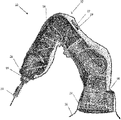
- FIG. 1 is a perspective view of a robotic system with a transparent protective drape joined to a robotic arm with rotationally unconstrained rings at the fixed base of the robot and at the rotating tool attachment of an end effector in accordance with embodiments of the invention;
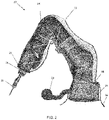
- FIG. 2 is a perspective view of a robotic system with a transparent protective drape joined to a robotic arm that includes a blower to control a desired pressure within the protective drape in accordance with embodiments of the invention
- FIG. 3 is a perspective view of a protective drape in a folded state to aid in transportation and to facilitate installation in accordance with embodiments of the invention
- FIG. 4 is a perspective view of a robotic system with a segmented transparent protective drape joined with sectional rings, and joined to a robotic arm with rotationally unconstrained rings at the fixed base of the robot and at the rotating tool attachment point of an end effector in accordance with embodiments of the invention;
- FIG. 5 is a perspective view of a robotic system with a segmented transparent protective drape joined with sectional rings, where the sectional rings are joined to the robot arm, and the ends of the protective drape are joined to a robotic arm with rotationally unconstrained rings at the fixed base of the robot and at the rotating tool attachment point of an end effector in accordance with embodiments of the invention;
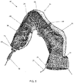
- FIG. 6 is a perspective view of a robotic system with a transparent protective drape with draw cords to remove excess slack at different points along the length of the protective drape, the protective drape joined to a robotic arm with rotationally unconstrained rings at the fixed base of the robot and at the rotating tool attachment point of an end effector in accordance with embodiments of the invention;
- FIG. 7 is a perspective view of a robotic system with a transparent protective drape with an irrigation, vacuum, or air tube/line forming a skeleton along the length of the protective drape, the protective drape joined to a robotic arm with rotationally unconstrained rings at the fixed base of the robot and at the rotating tool attachment point of an end effector in accordance with embodiments of the invention;
- FIG. 8 is an illustrative depiction of a protective drape with two protective tubes to control fluid flow for temperature control in accordance with embodiments of the invention.
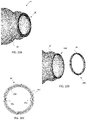
- FIGS. 9A-9C depict a protective drape in accordance with embodiments of the invention, where FIG. 9A is an assembled view of the protective drape, FIG. 9B is an exploded view thereof, and FIG. 9C is a cross-sectional view of a rotationally unconstrained ring and a portion of a protective tube.
- FIGS. 10A-10C depict a protective drape in accordance with embodiments of the invention, where FIG. 10A is an assembled view of the protective drape, FIG. 10B is an exploded view thereof, and FIG. 10C is a plan view of a rotationally unconstrained ring.
- the present invention has utility as a protective draping for a robot of a robotic system.
- the following description of various embodiments of the invention is not intended to limit the invention to these specific embodiments, but rather to enable any person skilled in the art to make and use this invention through exemplary aspects thereof.
- range is intended to encompass not only the end point values of the range but also intermediate values of the range as explicitly being included within the range and varying by the last significant figure of the range.
- a recited range from 1 to 4 is intended to include 1-2, 1-3, 2-4, 3-4, and 1-4.
- Embodiments of the present invention describe a protective drape for, and method of usage with a robotic system. It should be appreciated that any autonomous (i.e., active), semi-autonomous, passive, or haptic robotic system either for medical or industrial applications may benefit from the system and methods disclosed herein. Embodiments of the invention may be used with robotic systems that are required to operate in varied environments that illustratively include industrial applications, a sterile surgical suite for patient care, and a clean room for manufacturing sensitive electronic components.
- Embodiments described herein make reference to a robotic system. It should be understood that the robotic system may further include external components such as external hardware and software, tracking systems, external user interfaces and external user input mechanisms. The external components may require additional protective draping independent of the robotic system described herein, unless otherwise stated. Examples of the components and control of a robotic system are described in U.S. patent application Ser. No. 12/703,125 and U.S. Pat. No. 5,806,518.
- robotic systems examples include the LBR iiwa Lightweight Industrial Robot Series (KUKA Robotics Corp., Shelby Township, Mich.), the ROBODOC® Surgical System (THINK Surgical, Inc., Fremont, Calif.), and the RIO® Robotic System (Mako Surgical Corp., Ft. Lauderdale, Fla.).
- Embodiments of the protective drape may be made of paper, woven materials, fabrics, plastic films, plastic sheets, foils, and combinations thereof.
- an inventive drape is formed with transparent plastic film to allow visual inspection of an encapsulated robot without compromising the position or integrity of the protective drape.
- FIG. 1 depicts a draped robotic system 10 in accordance with an embodiment of the invention.
- the robotic system 10 may include a segmented robotic arm 14 that rotates on a base 16 , and an end effector manipulator 18 (i.e., a most distal segment/link of the robotic arm 14 ) that rotates relative to the robotic arm 14 .
- a most distal portion of the robotic system 10 is an end effector 20 that may be removably attached to the end effector manipulator 18 .
- An end-effector 20 may refer to a tool that directly interacts with the environment, and may also refer to one or more components associated with a tool.
- Examples of an end-effector include a cutter, an end-mill, a drill bit, and a saw, as well as one or more components associated with the tool such as a housing/casing for a tool, a handle of a tool, a motor for driving a tool, or other components associated with a tool.
- An end-effector 20 may also refer to a device, an apparatus, or an assembly of components that attaches to a most distal segment/link of a robotic arm 14 .
- the most proximal portion of the robotic system 10 is the base 16 .
- the segments (or links) of the robotic arm 14 may be connected by various revolute, prismatic or spherical joints to actuate the end effector 20 in one or more degrees of freedom, preferably five or more.
- the protective drape 22 is formed of a sheet material formed as a tube 25 that is joined to the robotic system 10 with rotationally unconstrained rings 24 and 28 .
- the ring 28 may be joined to a distal portion of the robotic system 10 , such as the end effector 20 , or the end effector manipulator 18 .
- Ring 24 may be joined to a more proximal portion of the draped robotic system 10 such as the base 16 or a proximal segment of the robotic arm 14 .
- the drape 22 is depicted as being formed of a transparent material, such as polyethylene; however, it is appreciated that paper, woven materials, fabrics, non-transparent plastic films or sheets, foils, and combinations thereof are also suitable for the formation of the drape 22 .
- the protective tube 25 that forms the protective drape 22 may be formed according to the shape and size of the robotic system 10 .
- the protective tube 25 may be formed or manufactured in the shape of a hollow cylinder, hollow square, or of any hollow irregular shape depending on the type or geometry of the robotic system 10 .
- the protective tube 25 may be readily formed by joining opposing sheet edges to define, for example a hollow cylinder, or may be formed by a seamless film or foil, by conventional techniques. It is also appreciated that luminal segments of like or different material are readily joined to form a segmented protective drape. Alternatively, swatches of sheet material may be joined to form a tube 25 with a quilt-like pattern.
- the rings ( 24 , 28 ) may be formed of rigid or semi-rigid materials illustratively including metals or polymers.
- the rings ( 24 , 28 ) may or may not be shaped and sized according to the shape and size of the portions of the robotic arm where the rings ( 24 , 28 ) are adapted to reside.
- the rings ( 24 , 28 ) may be circular as depicted throughout the drawings, or confer other geometries including ovals, polygons, or organic shapes.
- the ends of the protective tube 25 may be joined to the rings ( 24 , 28 ) using techniques known in the art (e.g., adhesives, fastening elements (clasps, clamps, clips, screws, pins, hook and loop, etc.), shrink wrapped, heat wrapped, stitched, etc.).
- adhesives e.g., adhesives, fastening elements (clasps, clamps, clips, screws, pins, hook and loop, etc.), shrink wrapped, heat wrapped, stitched, etc.
- the ring 28 engages the end effector 20 .
- the use of rotationally unconstrained rings ( 24 , 28 ) allows the drape 22 to be attached to the end effector 20 directly rather than a link proximal to the last revolute joint, while the end effector 20 is free to rotate an unlimited number of rotations without constricting the drape 22 , and allows the wrist to perpetually invert while holding the end effector position for an unlimited number of rotations.
- the use of rings reduces the size of the drape for easy installation.
- the drape 22 has an opening 27 in a preselected position to provide access to the arm 14 or base 16 .
- a seal 29 provides for closure of the opening 27 .
- the seal 29 includes a contact adhesive strip, or a fastening structure as detailed in U.S. Pat. No. 5,809,621.
- the drape is a continuous sheet with adhesives to combine multiple drape components.
- having an opening with a seal can be advantageous if there are controls on the arm or on the base that require access. It is appreciated that a seal 29 is readily formed such that a sterile barrier exists between the robot 12 and the exterior environment.
- a robotic system 15 includes a blower, vacuum, or air compressor 23 to control the pressure within the protective drape 22 .
- the draped robotic system 10 has either a positive pressure or negative pressure within the protective drape 22 relative to the surrounding environment.
- a blower 23 may be used to create positive pressure inside the drape 22 , protecting the robotic system 15 and further serves to push the sheet material of the drape 22 away from moving components of the robotic system 15 .
- the robotic system 15 may include a pressure control system to control the direction of airflow. Therefore, depending on the application or stage of a procedure, the area between the robotic system 15 and the protective drape 22 may be toggled between a positive or negative pressure state. Additionally, one or more of the rings ( 24 , 28 ) may provide a hermetic seal to help control the pressure within the drape 22 . Although, a hermetic seal may not be necessary if the pressure differential is sufficient to maintain the pressure state.
- a set of rings ( 24 , 28 ), where one ring 28 is approximately the size of the end effector manipulator 18 or end effector 20 , or a ring that does not constrain rotation (i.e., a “slip ring”) of the end effector manipulator 18 or end effector 20 is used at the distal end of the protective drape 22 .
- the second ring 24 is a simple ring that is larger than the largest diameter of the robot arm 14 and base 16 .
- the protective drape 22 may be compressed or folded between the two rings ( 24 , 28 ) as shown in FIG. 3 .
- the protective drape 22 may have an accordion-type fold similar to that of a bellow.
- the drape 22 When deployed, as shown in FIG. 1 , the drape 22 may be shaped like the robotic arm 14 in a manner that the robotic system 10 is able to be moved throughout its entire range of motion without cinching the drape 22 . It is appreciated that cinching of the sheet material of the drape 22 can limit the operational range of the robotic system 10 in general, and the end effector 20 in particular; additionally, the barrier function of the drape 22 is compromised if the cinching results in a tear.
- the protective drape 22 is installed with a user holding the rings ( 24 , 28 ) in front of the robotic system 10 .
- the first ring 28 of the drape 22 is fixed to the distal end of the robotic system 10 (end effector 20 if attached, or end effector manipulator 18 if the end effector 20 is not attached) by a user.
- the robotic arm 14 then automatically moves or advances through the rings ( 24 , 28 ) in a manner that the user does not need to move the second ring 24 .
- the drape 22 unfolds until the user is holding the second ring 24 near the base 16 of the robotic system 10 .
- the user manually unfolds the drape 22 by holding the first ring 28 and moving the second ring 24 down the length of the arm 14 .
- a separate device (not shown) holds the two rings ( 24 , 28 ) of the folded drape 22 .
- the robotic system 10 automatically moves the end effector 20 to the device, where the end effector 20 either automatically attaches to the first ring 28 , or the user manually attaches the first ring 28 to the end effector.
- the robotic system 10 either moves the arm 14 through the second ring 24 , while the second ring 24 remains stationary, or, the robotic system 10 “picks up” the drape 22 , lifts the drape 22 above the arm 14 , and allows gravity to unfold the drape 22 along the robotic arm 14 .
- the second ring 24 may be attached to a base drape 26 to create a base seal.
- the base drape 26 may drape any additional components beyond the base 16 of the robotic system 10 , such as a supporting structure supported on the floor or a wall that might contain additional robotic hardware components.
- FIG. 4 is a perspective view of a robotic system 30 with a segmented protective drape 32 having drape segments 36 that are joined by sectional rings 34 in accordance with embodiments of the invention.
- the segmented protective drape 32 is joined to a robotic arm 14 with rotationally unconstrained rings ( 24 , 28 ) at the fixed base 16 of the robotic system 30 , and at the end effector manipulator 18 or end effector 20 .
- the sectional rings 34 may form a rigid connection between the segments 36
- the sectional rings 34 may form a rotationally-unconstrained connection between the segments 36 .
- FIG. 5 is a perspective view of a robotic system 40 with a segmented protective drape 32 joined with sectional rings 44 , where the sectional rings 44 are joined or clipped onto the robot arm 14 in accordance with embodiments of the invention.
- the ends of the protective drape 32 are joined to a robotic arm 14 with rotationally unconstrained rings ( 24 , 28 ) at the fixed base 16 of the robotic system 40 , and at the end effector manipulator 18 or end effector 20 .
- like numerals have the meaning ascribed thereto with respect to the preceding drawings.
- FIG. 6 is a perspective view of an embodiment of a robotic system 50 with a protective drape 52 with draw cords 54 to remove excess slack at different points along the length of the protective drape 52 .
- the protective drape 52 is joined to a robotic arm 14 with rotationally unconstrained rings at the fixed base 16 of the robot 12 and at the end effector manipulator 18 or end effector 20 .
- the use of draw cords 54 allows for a uniform-sized drape with uniform cross-section which is easier to manufacture, while allowing slack where needed but preventing excess slack where it is not needed.
- a tube-shaped protective drape 52 that has a larger diameter as the largest diameter section of the robotic system 50 , and allows the necessary slack to prevent twisting during rotation of the arm 14 , has locations along the length of the drape 52 where the cross-section of the robotic arm 14 is smaller and excess slack is not needed, draw cords 54 are placed within the drape 52 to allow the drape 52 to be cinched against the robot 12 .
- FIG. 7 is a perspective view of a robotic system 60 with a protective drape 62 with an irrigation, vacuum, or air tube/line 64 forming a skeleton along the length of the protective drape 62 in accordance with embodiments of the invention.
- the protective drape 62 is joined to the robotic arm 12 with rotationally unconstrained rings ( 24 , 28 ) at the fixed base 16 of the robotic system 60 and at the end effector manipulator 18 or end effector 20 .
- like numerals have the meaning ascribed thereto with respect to the preceding drawings.
- the irrigation, vacuum, or air tube/line 64 is in a helical or spring like pattern along the length of the protective drape 62 .
- the irrigation, vacuum, or air tube/line 64 may come pre-packaged and folded with the drape 62 such that unfolding the drape 62 also unwinds the irrigation tube/line 64 such that the irrigation tube/line 64 is in an optimal position on the robot 12 and ensures that the correct end of the irrigation tube/line 64 is at the end effector 18 when the drape 62 is deployed.
- the irrigation tube 64 may also provide an external “skeleton” to the drape 62 , preventing the drape 62 from binding up and facilitating an easier installation of the drape 62 .
- the irrigation tube/line 64 could be coiled such that unfolding the drape 62 keeps the drape 62 coiled around the robot 12 .
- a protective drape 70 for a robotic system may include an outer tube 72 and a second inner tube 74 incorporated within, wherein a fluid (e.g., cooling air) can pass there between.
- a blower 23 may be attached to the inner tube 74 near ring 24 to blow fluid over the components of the robotic system (i.e., direction of arrows 76 ) encapsulated within the inner tube 74 of the protective drape 70 .
- the fluid may then come out inside of the protective drape 70 near the front of the inner tube 74 and then through the space between the outer tube 72 and inner tube 74 (fluid flow direction is indicated by arrows 78 and 80 ).
- the fluid may then exit (indicated by arrow 82 ) back out near the blower 23 between the inner tube 74 and outer tube 72 .
- the protective drape 70 will keep the temperature of the robotic system within the inner tube 74 down, which otherwise could increase due to the enclosing of the robot hardware.
- the rings 24 and 28 of protective drape 70 may be attached to both the inner tube 74 and the outer tube 72 .
- ring 28 is attached to both the inner tube 74 and the outer tube 72
- ring 24 is only attached to the inner tube 74 to allow all the fluid to exit near the blower. If ring 28 is attached to both the inner tube 74 and the outer tube 72 , holes or other perforations may exist near the distal portion of the inner tube to allow fluid to pass to the space between the inner tube 74 and outer tube 72 . Therefore, the fluid may not expel near the end effector 20 where the surgical procedure is performed.
- FIGS. 9A-10C depict examples of a rotationally unconstrained ring 28 (i.e., “slip ring”).
- a rotationally unconstrained ring 28 may be fixed to a portion (e.g., segment of the robotic arm 14 , end-effector manipulator 18 , or end-effector 20 ) of the robotic arm 14 , and “slip” relative to any rotation of that portion of the robotic arm 14 to prevent the drape 22 or tube 25 from constricting (i.e., to prevent the drape 22 or tube 25 from rotating with the rotation of the robotic arm 14 ).
- a part or a portion of a rotationally unconstrained ring 28 may be fixed to the end-effector manipulator 18 to axially constrain (i.e., prevent translational motion along an axis) the ring 28 to the end-effector manipulator 18 .
- the rotationally unconstrained ring 28 now axially constrained to the end-effector manipulator 18 , allows the drape 22 or tube 25 to ‘slip’ relative to any rotation of the end-effector manipulator 18 during a robotic task.
- the rotationally unconstrained ring 28 prevents the drape 22 or tube 25 from rotating with the rotation of the end-effector manipulator 18 while axial constraining the ring 28 to the end-effector manipulator 18 .
- FIG. 9A depicts the drape 22 of FIG. 3 in an assembled state
- FIG. 9B depicts the drape 22 in an exploded view
- FIG. 9C is a cross-sectional view of the rotationally unconstrained ring 28 and a portion of the tube 25 .
- the rotationally unconstrained ring 28 includes an inner ring 28 a and an outer ring 28 b.
- the tube 25 of the drape 22 has a tube end 31 connected to the inner ring 28 a.
- the inner ring 28 a is located inside the outer ring 28 b and rotates relative to the outer ring 28 b.
- the outer ring 28 b may have a hollow interior to hold the inner ring 28 a therein.
- the outer ring 28 b may have an arced cross-section ranging between 181 degrees to 359 degrees to form a gap 33 between the arc ends. A portion of the tube 25 extends from the inner ring 28 a and out through the gap 33 of the outer ring 28 b.
- the outer ring 28 b may further include one or more built-in connection mechanisms 35 (e.g., a joint, a clip, a clasp) to connect or interlock with a corresponding mechanism on a portion of the robotic arm 14 (e.g., end-effector 20 , end-effector manipulator 18 ).
- the outer ring 28 b is fixed to the end-effector manipulator 18 (or other distal portion of the robotic arm 14 ) to axially constrain the rotationally unconstrained ring 28 to the robotic arm 14 .
- the outer ring 28 b may be fixed to the end-effector manipulator 18 with the built-in connection mechanism 35 or with other connection mechanisms (e.g., adhesives, fastening elements (pins, screws, clamps, clasps, hook and loop)).
- the tube 25 is then draped over the robotic arm 14 to position the second ring 24 at a proximal portion of the robotic arm 14 .
- the fixed outer ring 28 b rotates with the end-effector manipulator 18 , and the inner ring 28 a “slips” relative to rotation of the outer ring 28 b to prevent the drape 22 or tube 25 from rotating with the end-effector manipulator 18 .
- FIGS. 10A-10C another example of a rotationally unconstrained ring 28 ′ (i.e., “slip ring”) is shown in the form of a bearing, where FIG. 10A is an assembled view thereof, FIG. 10B is an exploded view thereof, and FIG. 10C is a plan view of the rotationally unconstrained ring 28 ′.
- the rotationally unconstrained ring 28 ′ includes an inner ring 28 a ′ and an outer ring 28 b ′.
- the outer ring 28 b ′ is connected to a tube end 31 of the tube 25 .
- the outer ring 28 b ′ and inner ring 28 a ′ form a bearing and may further include a race and a plurality of balls/rollers 29 to form a race bearing.
- the space between the inner ring 28 a ′ and the outer ring 28 b ′ may be sealed to form a sealed bearing to prevent contamination.
- the inner ring 28 a ′ may further include one or more built-in connection mechanisms ( 35 a, 35 b ) to connect or interlock with a corresponding mechanism on a portion of the robotic arm 14 (e.g., end-effector 20 , end-effector manipulator 18 ).
- the inner ring 28 b ′ is fixed to the end-effector manipulator 18 (or other distal portion of the robotic arm 14 ) to axially constrain the rotationally unconstrained ring 28 ′ to the robotic arm 14 .
- the inner ring 28 a ′ may be fixed to the end-effector manipulator 18 with the built-in connection mechanisms ( 35 a, 35 b ) or with other connection mechanisms (e.g., adhesives, fastening elements (pins, screws, clamps, clasps, hook and loop)).
- the tube 25 is then draped over the robotic arm 14 to position the second ring 24 at a proximal portion of the robotic arm 14 .
- the fixed inner ring 28 a ′ rotates with the end-effector manipulator 18 , and the outer ring 28 b ′ “slips” relative to the rotation of the inner ring 28 a ′ to prevent the drape 22 or tube 25 from rotating with the end-effector manipulator 18 .
Landscapes
- Health & Medical Sciences (AREA)
- Engineering & Computer Science (AREA)
- Surgery (AREA)
- Life Sciences & Earth Sciences (AREA)
- Robotics (AREA)
- Animal Behavior & Ethology (AREA)
- Medical Informatics (AREA)
- Molecular Biology (AREA)
- Heart & Thoracic Surgery (AREA)
- General Health & Medical Sciences (AREA)
- Public Health (AREA)
- Veterinary Medicine (AREA)
- Biomedical Technology (AREA)
- Mechanical Engineering (AREA)
- Nuclear Medicine, Radiotherapy & Molecular Imaging (AREA)
- Manipulator (AREA)
Abstract
Description
- This application is a continuation in part application of U.S. application Ser. No. 15/744,253 filed 12 Jan. 2018 that in turn is a U.S. National phase application of International Application Ser. No. PCT/US2016/4278
6filed 18 Jul. 2016 that claims priority benefit of U.S. ProvisionalApplication Serial Number 62/196,073 filed 23 Jul. 2015; the contents of which are hereby incorporated by reference. - The present invention generally relates to robotic systems, and more specifically to a protective drape for robotic systems.
- Robotic systems have been developed to aid in a variety of different applications ranging from the industrial, medical, and military fields. Robotic systems have unique characteristics to perform different tasks depending on the application to be performed, where the size, weight, geometry, construction, controls, programs and functionality are all characteristics considered when designing a robot.
- Robotic systems are required to operate in varied environments that range from industrial applications to a sterile surgical suite for patient care or a clean room for manufacturing sensitive electronic components. In each of these applications there is a need to prevent contaminants from infiltrating the robot and affecting operation, as well to prevent contaminants from the robot infecting a patient or contaminating product being assembled or tested by the robot. Furthermore, in surgical or medical environments sterile conditions are required to be maintained to prevent the transfer of infectious agents between successive patients being treated by a robot.
- A robotic system used in surgery must either be sterile or covered by a sterile drape, while an industrial robot often has a similar protective cover. Often, part of the robotic system must extend beyond the drape so that those parts can interact with the environment beyond the drape to perform desired tasks. In a robotic system with a large range of motion, fixing a drape to the operational end of the robotic system often leads to drape constriction. The resulting twisting and tightening of the drape around the robotic system requires manual adjustments of the drape. This may be alleviated by using a protective drape that is larger than needed to cover the system. With a larger protective drape the robot manipulator has more room to articulate reducing the chances of drape constriction. However, this excess material can interfere with the surgical procedure and use of the device. In addition, a larger protective drape requires additional drape material that is counterintuitive to install since the drape may not resemble the shape of the robot. On the other hand, a protective drape that has a conforming shape to the robot can be difficult to maneuver around the robot during installation.
- Currently, tubes that are used to deliver fluid, such as sterile irrigation fluid, to the end effector of the robot must be routed around a protective drape after the drape is installed. This can be a difficult process, particularly keeping the irrigation tube sterile during installation and having the tube oriented in the correct direction. Additionally, exchange of such tubes is often required between surgical procedures owing to the external placement.
- Thus there is a need in the art for protective draping for robotic systems that are easy to install, does not restrict the robots movement, and allows the robotic system to perform a specified task.
- A protective drape for a robotic system is provided that includes a protective tube encapsulating at least a portion of the robotic system with a first ring connected to, or in proximity to a first end perimeter of the protective tube and adapted to fit around a distal portion of the robotic system. A second ring is connected to a second end perimeter of the protective tube, where the second ring is configured to fit around a proximal portion of the robotic system without constraining the rotation of a robotic arm. One or more draw cords are provided to remove excess slack at different points along the length of the protective tube and the robotic arm.
- A protective drape for a robotic system is provided that includes a plurality of drape segments adapted to collectively encapsulate at least a portion of the robotic system, with one or more sectional rings positioned between and joining the plurality of drape segments. A first ring is connected to a first end perimeter of the collective drape segments, where the first ring is configured to fit around a distal portion of the robotic system, and a second ring is connected to a second end perimeter of the collective drape segments, where the second ring is configured to fit around a proximal portion of the robotic system.
- A protective drape for a robotic system is provided that includes a protective tube having a length configured to encapsulate a robotic arm. A first ring is connected to a first end perimeter of the protective tube, where the first ring is configured to fit around a distal portion of the robotic arm, and a second ring is connected to a second end perimeter of the protective tube, where the second ring is configured to fit around a proximal portion of the robotic arm, and an irrigation, vacuum, or air tube/line is integrated with the protective tube.
- A method is provided for deploying a protective drape to encapsulate a robotic system, where the method includes holding a tube of the protective drape alone or connected to at least one of a pair of rings in front of the robotic system; and automatically moving or advancing a robotic arm of the robotic system through the protective tube to encapsulate the robotic system.
- The present invention is further detailed with respect to the following drawings that are intended to show certain aspects of the present invention, but should not be construed as a limit on the practice of the present invention.
-
FIG. 1 is a perspective view of a robotic system with a transparent protective drape joined to a robotic arm with rotationally unconstrained rings at the fixed base of the robot and at the rotating tool attachment of an end effector in accordance with embodiments of the invention; -
FIG. 2 is a perspective view of a robotic system with a transparent protective drape joined to a robotic arm that includes a blower to control a desired pressure within the protective drape in accordance with embodiments of the invention; -
FIG. 3 is a perspective view of a protective drape in a folded state to aid in transportation and to facilitate installation in accordance with embodiments of the invention; -
FIG. 4 is a perspective view of a robotic system with a segmented transparent protective drape joined with sectional rings, and joined to a robotic arm with rotationally unconstrained rings at the fixed base of the robot and at the rotating tool attachment point of an end effector in accordance with embodiments of the invention; -
FIG. 5 is a perspective view of a robotic system with a segmented transparent protective drape joined with sectional rings, where the sectional rings are joined to the robot arm, and the ends of the protective drape are joined to a robotic arm with rotationally unconstrained rings at the fixed base of the robot and at the rotating tool attachment point of an end effector in accordance with embodiments of the invention; -
FIG. 6 is a perspective view of a robotic system with a transparent protective drape with draw cords to remove excess slack at different points along the length of the protective drape, the protective drape joined to a robotic arm with rotationally unconstrained rings at the fixed base of the robot and at the rotating tool attachment point of an end effector in accordance with embodiments of the invention; -
FIG. 7 is a perspective view of a robotic system with a transparent protective drape with an irrigation, vacuum, or air tube/line forming a skeleton along the length of the protective drape, the protective drape joined to a robotic arm with rotationally unconstrained rings at the fixed base of the robot and at the rotating tool attachment point of an end effector in accordance with embodiments of the invention; and -
FIG. 8 is an illustrative depiction of a protective drape with two protective tubes to control fluid flow for temperature control in accordance with embodiments of the invention. -
FIGS. 9A-9C depict a protective drape in accordance with embodiments of the invention, whereFIG. 9A is an assembled view of the protective drape,FIG. 9B is an exploded view thereof, andFIG. 9C is a cross-sectional view of a rotationally unconstrained ring and a portion of a protective tube. -
FIGS. 10A-10C depict a protective drape in accordance with embodiments of the invention, whereFIG. 10A is an assembled view of the protective drape,FIG. 10B is an exploded view thereof, andFIG. 10C is a plan view of a rotationally unconstrained ring. - The present invention has utility as a protective draping for a robot of a robotic system. The following description of various embodiments of the invention is not intended to limit the invention to these specific embodiments, but rather to enable any person skilled in the art to make and use this invention through exemplary aspects thereof.
- It is to be understood that in instances where a range of values are provided that the range is intended to encompass not only the end point values of the range but also intermediate values of the range as explicitly being included within the range and varying by the last significant figure of the range. By way of example, a recited range from 1 to 4 is intended to include 1-2, 1-3, 2-4, 3-4, and 1-4.
- Embodiments of the present invention describe a protective drape for, and method of usage with a robotic system. It should be appreciated that any autonomous (i.e., active), semi-autonomous, passive, or haptic robotic system either for medical or industrial applications may benefit from the system and methods disclosed herein. Embodiments of the invention may be used with robotic systems that are required to operate in varied environments that illustratively include industrial applications, a sterile surgical suite for patient care, and a clean room for manufacturing sensitive electronic components. In each of these applications where embodiments of the invention are employed, there is a need to prevent contaminants from infiltrating from the environment to the robot and affecting operation of the robot itself or the robotic system, as well to prevent contaminants from the robot from infecting a patient or contaminating an assembly or process product. Furthermore, in surgical or medical environments sterile conditions are required to be maintained to prevent the transfer of infectious agents between patients being treated by the robots; the present invention addresses these requirements with the deployment of a protective drape that is different and superior to the prior art.
- Embodiments described herein make reference to a robotic system. It should be understood that the robotic system may further include external components such as external hardware and software, tracking systems, external user interfaces and external user input mechanisms. The external components may require additional protective draping independent of the robotic system described herein, unless otherwise stated. Examples of the components and control of a robotic system are described in U.S. patent application Ser. No. 12/703,125 and U.S. Pat. No. 5,806,518. Examples of such robotic systems include the LBR iiwa Lightweight Industrial Robot Series (KUKA Robotics Corp., Shelby Township, Mich.), the ROBODOC® Surgical System (THINK Surgical, Inc., Fremont, Calif.), and the RIO® Robotic System (Mako Surgical Corp., Ft. Lauderdale, Fla.).
- Embodiments of the protective drape may be made of paper, woven materials, fabrics, plastic films, plastic sheets, foils, and combinations thereof. In certain inventive embodiments, an inventive drape is formed with transparent plastic film to allow visual inspection of an encapsulated robot without compromising the position or integrity of the protective drape.
- Referring now to the figures,
FIG. 1 depicts a drapedrobotic system 10 in accordance with an embodiment of the invention. Therobotic system 10 may include a segmentedrobotic arm 14 that rotates on abase 16, and an end effector manipulator 18 (i.e., a most distal segment/link of the robotic arm 14) that rotates relative to therobotic arm 14. A most distal portion of therobotic system 10 is anend effector 20 that may be removably attached to theend effector manipulator 18. An end-effector 20 may refer to a tool that directly interacts with the environment, and may also refer to one or more components associated with a tool. Examples of an end-effector include a cutter, an end-mill, a drill bit, and a saw, as well as one or more components associated with the tool such as a housing/casing for a tool, a handle of a tool, a motor for driving a tool, or other components associated with a tool. An end-effector 20 may also refer to a device, an apparatus, or an assembly of components that attaches to a most distal segment/link of arobotic arm 14. The most proximal portion of therobotic system 10 is thebase 16. The segments (or links) of therobotic arm 14 may be connected by various revolute, prismatic or spherical joints to actuate theend effector 20 in one or more degrees of freedom, preferably five or more. Theprotective drape 22 is formed of a sheet material formed as atube 25 that is joined to therobotic system 10 with rotationallyunconstrained rings ring 28 may be joined to a distal portion of therobotic system 10, such as theend effector 20, or theend effector manipulator 18.Ring 24 may be joined to a more proximal portion of the drapedrobotic system 10 such as the base 16 or a proximal segment of therobotic arm 14. For the purposes of visual clarity, thedrape 22 is depicted as being formed of a transparent material, such as polyethylene; however, it is appreciated that paper, woven materials, fabrics, non-transparent plastic films or sheets, foils, and combinations thereof are also suitable for the formation of thedrape 22. Theprotective tube 25 that forms theprotective drape 22 may be formed according to the shape and size of therobotic system 10. For example, theprotective tube 25 may be formed or manufactured in the shape of a hollow cylinder, hollow square, or of any hollow irregular shape depending on the type or geometry of therobotic system 10. Additionally, theprotective tube 25 may be readily formed by joining opposing sheet edges to define, for example a hollow cylinder, or may be formed by a seamless film or foil, by conventional techniques. It is also appreciated that luminal segments of like or different material are readily joined to form a segmented protective drape. Alternatively, swatches of sheet material may be joined to form atube 25 with a quilt-like pattern. - The rings (24, 28) may be formed of rigid or semi-rigid materials illustratively including metals or polymers. The rings (24, 28) may or may not be shaped and sized according to the shape and size of the portions of the robotic arm where the rings (24, 28) are adapted to reside. For example, the rings (24, 28) may be circular as depicted throughout the drawings, or confer other geometries including ovals, polygons, or organic shapes. The ends of the
protective tube 25 may be joined to the rings (24, 28) using techniques known in the art (e.g., adhesives, fastening elements (clasps, clamps, clips, screws, pins, hook and loop, etc.), shrink wrapped, heat wrapped, stitched, etc.). - In some inventive embodiments, the
ring 28 engages theend effector 20. The use of rotationally unconstrained rings (24, 28) allows thedrape 22 to be attached to theend effector 20 directly rather than a link proximal to the last revolute joint, while theend effector 20 is free to rotate an unlimited number of rotations without constricting thedrape 22, and allows the wrist to perpetually invert while holding the end effector position for an unlimited number of rotations. The use of rings reduces the size of the drape for easy installation. - In some inventive embodiments, the
drape 22 has anopening 27 in a preselected position to provide access to thearm 14 orbase 16. Aseal 29 provides for closure of theopening 27. Theseal 29 includes a contact adhesive strip, or a fastening structure as detailed in U.S. Pat. No. 5,809,621. Typically the drape is a continuous sheet with adhesives to combine multiple drape components. However, having an opening with a seal can be advantageous if there are controls on the arm or on the base that require access. It is appreciated that aseal 29 is readily formed such that a sterile barrier exists between therobot 12 and the exterior environment. - In still other embodiments of the present invention, with respect to
FIG. 2 , a robotic system 15 includes a blower, vacuum, orair compressor 23 to control the pressure within theprotective drape 22. Depending on the nature of the work environment, the drapedrobotic system 10 has either a positive pressure or negative pressure within theprotective drape 22 relative to the surrounding environment. By way of example, in an industrial setting with corrosive or particle ladened environment, ablower 23 may be used to create positive pressure inside thedrape 22, protecting the robotic system 15 and further serves to push the sheet material of thedrape 22 away from moving components of the robotic system 15. In a medical setting, it may be advantageous to have avacuum 23 to create negative pressure within theprotective drape 22 such that particles or debris on the robotic system 15 cannot escape or contaminate the surgical field. In certain inventive embodiments, the robotic system 15 may include a pressure control system to control the direction of airflow. Therefore, depending on the application or stage of a procedure, the area between the robotic system 15 and theprotective drape 22 may be toggled between a positive or negative pressure state. Additionally, one or more of the rings (24, 28) may provide a hermetic seal to help control the pressure within thedrape 22. Although, a hermetic seal may not be necessary if the pressure differential is sufficient to maintain the pressure state. - In a particular inventive embodiment, with respect to
FIGS. 1 and 3 , a set of rings (24, 28), where onering 28 is approximately the size of theend effector manipulator 18 orend effector 20, or a ring that does not constrain rotation (i.e., a “slip ring”) of theend effector manipulator 18 orend effector 20 is used at the distal end of theprotective drape 22. Thesecond ring 24 is a simple ring that is larger than the largest diameter of therobot arm 14 andbase 16. Theprotective drape 22 may be compressed or folded between the two rings (24, 28) as shown inFIG. 3 . For example, theprotective drape 22 may have an accordion-type fold similar to that of a bellow. When deployed, as shown inFIG. 1 , thedrape 22 may be shaped like therobotic arm 14 in a manner that therobotic system 10 is able to be moved throughout its entire range of motion without cinching thedrape 22. It is appreciated that cinching of the sheet material of thedrape 22 can limit the operational range of therobotic system 10 in general, and theend effector 20 in particular; additionally, the barrier function of thedrape 22 is compromised if the cinching results in a tear. - In a particular inventive method, the
protective drape 22 is installed with a user holding the rings (24, 28) in front of therobotic system 10. Thefirst ring 28 of thedrape 22 is fixed to the distal end of the robotic system 10 (end effector 20 if attached, or endeffector manipulator 18 if theend effector 20 is not attached) by a user. Therobotic arm 14 then automatically moves or advances through the rings (24, 28) in a manner that the user does not need to move thesecond ring 24. As therobotic arm 14 moves through thesecond ring 24, thedrape 22 unfolds until the user is holding thesecond ring 24 near thebase 16 of therobotic system 10. In a specific embodiment, the user manually unfolds thedrape 22 by holding thefirst ring 28 and moving thesecond ring 24 down the length of thearm 14. In another embodiment, a separate device (not shown) holds the two rings (24, 28) of the foldeddrape 22. Therobotic system 10 automatically moves theend effector 20 to the device, where theend effector 20 either automatically attaches to thefirst ring 28, or the user manually attaches thefirst ring 28 to the end effector. Subsequently, therobotic system 10 either moves thearm 14 through thesecond ring 24, while thesecond ring 24 remains stationary, or, therobotic system 10 “picks up” thedrape 22, lifts thedrape 22 above thearm 14, and allows gravity to unfold thedrape 22 along therobotic arm 14. After thesecond ring 24 is at thebase 16 of therobotic system 10, thesecond ring 24 may be attached to abase drape 26 to create a base seal. Thebase drape 26 may drape any additional components beyond thebase 16 of therobotic system 10, such as a supporting structure supported on the floor or a wall that might contain additional robotic hardware components. -
FIG. 4 is a perspective view of arobotic system 30 with a segmentedprotective drape 32 havingdrape segments 36 that are joined bysectional rings 34 in accordance with embodiments of the invention. The segmentedprotective drape 32 is joined to arobotic arm 14 with rotationally unconstrained rings (24, 28) at the fixedbase 16 of therobotic system 30, and at theend effector manipulator 18 orend effector 20. With respect toFIG. 4 , like numerals have the meaning ascribed thereto with respect to the preceding drawing. In a specific embodiment, the sectional rings 34 may form a rigid connection between thesegments 36, or the sectional rings 34 may form a rotationally-unconstrained connection between thesegments 36. -
FIG. 5 is a perspective view of arobotic system 40 with a segmentedprotective drape 32 joined withsectional rings 44, where the sectional rings 44 are joined or clipped onto therobot arm 14 in accordance with embodiments of the invention. The ends of theprotective drape 32 are joined to arobotic arm 14 with rotationally unconstrained rings (24, 28) at the fixedbase 16 of therobotic system 40, and at theend effector manipulator 18 orend effector 20. With respect toFIG. 5 , like numerals have the meaning ascribed thereto with respect to the preceding drawings. -
FIG. 6 is a perspective view of an embodiment of arobotic system 50 with aprotective drape 52 withdraw cords 54 to remove excess slack at different points along the length of theprotective drape 52. With respect toFIG. 6 , like numerals have the meaning ascribed thereto with respect to the preceding drawings. Theprotective drape 52 is joined to arobotic arm 14 with rotationally unconstrained rings at the fixedbase 16 of therobot 12 and at theend effector manipulator 18 orend effector 20. The use ofdraw cords 54 allows for a uniform-sized drape with uniform cross-section which is easier to manufacture, while allowing slack where needed but preventing excess slack where it is not needed. In a specific embodiment, a tube-shapedprotective drape 52 that has a larger diameter as the largest diameter section of therobotic system 50, and allows the necessary slack to prevent twisting during rotation of thearm 14, has locations along the length of thedrape 52 where the cross-section of therobotic arm 14 is smaller and excess slack is not needed, drawcords 54 are placed within thedrape 52 to allow thedrape 52 to be cinched against therobot 12. -
FIG. 7 is a perspective view of arobotic system 60 with aprotective drape 62 with an irrigation, vacuum, or air tube/line 64 forming a skeleton along the length of theprotective drape 62 in accordance with embodiments of the invention. Theprotective drape 62 is joined to therobotic arm 12 with rotationally unconstrained rings (24, 28) at the fixedbase 16 of therobotic system 60 and at theend effector manipulator 18 orend effector 20. With respect toFIG. 7 , like numerals have the meaning ascribed thereto with respect to the preceding drawings. In a specific embodiment the irrigation, vacuum, or air tube/line 64 is in a helical or spring like pattern along the length of theprotective drape 62. - In a specific embodiment, the irrigation, vacuum, or air tube/
line 64 may come pre-packaged and folded with thedrape 62 such that unfolding thedrape 62 also unwinds the irrigation tube/line 64 such that the irrigation tube/line 64 is in an optimal position on therobot 12 and ensures that the correct end of the irrigation tube/line 64 is at theend effector 18 when thedrape 62 is deployed. In specific embodiments, theirrigation tube 64 may also provide an external “skeleton” to thedrape 62, preventing thedrape 62 from binding up and facilitating an easier installation of thedrape 62. The irrigation tube/line 64 could be coiled such that unfolding thedrape 62 keeps thedrape 62 coiled around therobot 12. - In a particular inventive embodiment, with respect to
FIG. 8 , aprotective drape 70 for a robotic system may include anouter tube 72 and a secondinner tube 74 incorporated within, wherein a fluid (e.g., cooling air) can pass there between. Ablower 23 may be attached to theinner tube 74 nearring 24 to blow fluid over the components of the robotic system (i.e., direction of arrows 76) encapsulated within theinner tube 74 of theprotective drape 70. The fluid may then come out inside of theprotective drape 70 near the front of theinner tube 74 and then through the space between theouter tube 72 and inner tube 74 (fluid flow direction is indicated byarrows 78 and 80). The fluid may then exit (indicated by arrow 82) back out near theblower 23 between theinner tube 74 andouter tube 72. Theprotective drape 70 will keep the temperature of the robotic system within theinner tube 74 down, which otherwise could increase due to the enclosing of the robot hardware. - The
rings protective drape 70 may be attached to both theinner tube 74 and theouter tube 72. In a specific embodiment,ring 28 is attached to both theinner tube 74 and theouter tube 72, whilering 24 is only attached to theinner tube 74 to allow all the fluid to exit near the blower. Ifring 28 is attached to both theinner tube 74 and theouter tube 72, holes or other perforations may exist near the distal portion of the inner tube to allow fluid to pass to the space between theinner tube 74 andouter tube 72. Therefore, the fluid may not expel near theend effector 20 where the surgical procedure is performed. -
FIGS. 9A-10C , depict examples of a rotationally unconstrained ring 28 (i.e., “slip ring”). As previously described, a rotationallyunconstrained ring 28 may be fixed to a portion (e.g., segment of therobotic arm 14, end-effector manipulator 18, or end-effector 20) of therobotic arm 14, and “slip” relative to any rotation of that portion of therobotic arm 14 to prevent thedrape 22 ortube 25 from constricting (i.e., to prevent thedrape 22 ortube 25 from rotating with the rotation of the robotic arm 14). For example, a part or a portion of a rotationallyunconstrained ring 28 may be fixed to the end-effector manipulator 18 to axially constrain (i.e., prevent translational motion along an axis) thering 28 to the end-effector manipulator 18. The rotationallyunconstrained ring 28, now axially constrained to the end-effector manipulator 18, allows thedrape 22 ortube 25 to ‘slip’ relative to any rotation of the end-effector manipulator 18 during a robotic task. In other words, the rotationallyunconstrained ring 28 prevents thedrape 22 ortube 25 from rotating with the rotation of the end-effector manipulator 18 while axial constraining thering 28 to the end-effector manipulator 18. This allows the end-effector manipulator 18 to rotate an unlimited number of times without constricting thedrape 22 ortube 25. It also allows the end-effector manipulator 18 to perpetually invert, by of a wrist joint of the robotic arm, without having the rotationallyunconstrained ring 18 anddrape 22 axially fall-off therobotic arm 14. -
FIG. 9A depicts thedrape 22 ofFIG. 3 in an assembled state,FIG. 9B depicts thedrape 22 in an exploded view, andFIG. 9C is a cross-sectional view of the rotationallyunconstrained ring 28 and a portion of thetube 25. The rotationallyunconstrained ring 28 includes aninner ring 28 a and anouter ring 28 b. Thetube 25 of thedrape 22 has atube end 31 connected to theinner ring 28 a. As best seen inFIG. 9C , theinner ring 28 a is located inside theouter ring 28 b and rotates relative to theouter ring 28 b. Theouter ring 28 b may have a hollow interior to hold theinner ring 28 a therein. Theouter ring 28 b may have an arced cross-section ranging between 181 degrees to 359 degrees to form agap 33 between the arc ends. A portion of thetube 25 extends from theinner ring 28 a and out through thegap 33 of theouter ring 28 b. Theouter ring 28 b may further include one or more built-in connection mechanisms 35 (e.g., a joint, a clip, a clasp) to connect or interlock with a corresponding mechanism on a portion of the robotic arm 14 (e.g., end-effector 20, end-effector manipulator 18). To install thedrape 22 on therobotic arm 14, theouter ring 28 b is fixed to the end-effector manipulator 18 (or other distal portion of the robotic arm 14) to axially constrain the rotationallyunconstrained ring 28 to therobotic arm 14. Theouter ring 28 b may be fixed to the end-effector manipulator 18 with the built-inconnection mechanism 35 or with other connection mechanisms (e.g., adhesives, fastening elements (pins, screws, clamps, clasps, hook and loop)). Thetube 25 is then draped over therobotic arm 14 to position thesecond ring 24 at a proximal portion of therobotic arm 14. During a robotic task, the fixedouter ring 28 b rotates with the end-effector manipulator 18, and theinner ring 28 a “slips” relative to rotation of theouter ring 28 b to prevent thedrape 22 ortube 25 from rotating with the end-effector manipulator 18. This allows the end-effector manipulator 18 to rotate an unlimited number of times without constricting thedrape 22 ortube 25. - With reference to
FIGS. 10A-10C , another example of a rotationallyunconstrained ring 28′ (i.e., “slip ring”) is shown in the form of a bearing, whereFIG. 10A is an assembled view thereof,FIG. 10B is an exploded view thereof, andFIG. 10C is a plan view of the rotationallyunconstrained ring 28′. The rotationallyunconstrained ring 28′ includes aninner ring 28 a′ and anouter ring 28 b′. Theouter ring 28 b′ is connected to atube end 31 of thetube 25. Theouter ring 28 b′ andinner ring 28 a′ form a bearing and may further include a race and a plurality of balls/rollers 29 to form a race bearing. The space between theinner ring 28 a′ and theouter ring 28 b′ may be sealed to form a sealed bearing to prevent contamination. Theinner ring 28 a′ may further include one or more built-in connection mechanisms (35 a, 35 b) to connect or interlock with a corresponding mechanism on a portion of the robotic arm 14 (e.g., end-effector 20, end-effector manipulator 18). To install thedrape 22 on therobotic arm 14, theinner ring 28 b′ is fixed to the end-effector manipulator 18 (or other distal portion of the robotic arm 14) to axially constrain the rotationallyunconstrained ring 28′ to therobotic arm 14. Theinner ring 28 a′ may be fixed to the end-effector manipulator 18 with the built-in connection mechanisms (35 a, 35 b) or with other connection mechanisms (e.g., adhesives, fastening elements (pins, screws, clamps, clasps, hook and loop)). Thetube 25 is then draped over therobotic arm 14 to position thesecond ring 24 at a proximal portion of therobotic arm 14. During a robotic task, the fixedinner ring 28 a′ rotates with the end-effector manipulator 18, and theouter ring 28 b′ “slips” relative to the rotation of theinner ring 28 a′ to prevent thedrape 22 ortube 25 from rotating with the end-effector manipulator 18. This allows the end-effector manipulator 18 to rotate an unlimited number of times without constricting thedrape 22 ortube 25. - While at least one exemplary embodiment has been presented in the foregoing detailed description, it should be appreciated that a vast number of variations exist. It should also be appreciated that the exemplary embodiment or exemplary embodiments are only examples, and are not intended to limit the scope, applicability, or configuration of the described embodiments in any way. Rather, the foregoing detailed description will provide those skilled in the art with a convenient road map for implementing the exemplary embodiment or exemplary embodiments. It should be understood that various changes may be made in the function and arrangement of elements without departing from the scope as set forth in the appended claims and the legal equivalents thereof.
Claims (20)
Priority Applications (1)
| Application Number | Priority Date | Filing Date | Title |
|---|---|---|---|
| US17/686,617 US20220184823A1 (en) | 2015-07-23 | 2022-03-04 | Protective drape for robotic systems |
Applications Claiming Priority (4)
| Application Number | Priority Date | Filing Date | Title |
|---|---|---|---|
| US201562196073P | 2015-07-23 | 2015-07-23 | |
| PCT/US2016/042786 WO2017015207A1 (en) | 2015-07-23 | 2016-07-18 | Protective drape for robotic systems |
| US201815744253A | 2018-01-12 | 2018-01-12 | |
| US17/686,617 US20220184823A1 (en) | 2015-07-23 | 2022-03-04 | Protective drape for robotic systems |
Related Parent Applications (2)
| Application Number | Title | Priority Date | Filing Date |
|---|---|---|---|
| PCT/US2016/042786 Continuation-In-Part WO2017015207A1 (en) | 2015-07-23 | 2016-07-18 | Protective drape for robotic systems |
| US15/744,253 Continuation-In-Part US20180200014A1 (en) | 2015-07-23 | 2016-07-18 | Protective drape for robotic systems |
Publications (1)
| Publication Number | Publication Date |
|---|---|
| US20220184823A1 true US20220184823A1 (en) | 2022-06-16 |
Family
ID=81943113
Family Applications (1)
| Application Number | Title | Priority Date | Filing Date |
|---|---|---|---|
| US17/686,617 Abandoned US20220184823A1 (en) | 2015-07-23 | 2022-03-04 | Protective drape for robotic systems |
Country Status (1)
| Country | Link |
|---|---|
| US (1) | US20220184823A1 (en) |
Cited By (5)
| Publication number | Priority date | Publication date | Assignee | Title |
|---|---|---|---|---|
| US20200086509A1 (en) * | 2018-09-13 | 2020-03-19 | The Charles Stark Draper Laboratory, Inc. | Food-Safe, Washable, Thermally-Conductive Robot Cover |
| US12167902B2 (en) | 2015-10-16 | 2024-12-17 | Medical Microinstruments, Inc. | Robotic surgical assembly |
| US12478398B2 (en) | 2021-06-21 | 2025-11-25 | Medical Microinstruments, Inc. | Surgical instrument for robotic surgery |
| US12575825B2 (en) | 2021-10-13 | 2026-03-17 | Medical Microinstruments, Inc. | Method of manufacturing a gripping surface for an end effector and surgical instrument comprising a gripping end effector |
| US12616542B2 (en) | 2017-04-14 | 2026-05-05 | Medical Microinstruments, Inc. | Robotic microsurgical assembly |
Citations (10)
| Publication number | Priority date | Publication date | Assignee | Title |
|---|---|---|---|---|
| US4550713A (en) * | 1983-03-10 | 1985-11-05 | Hyman Frederic E Dr | Method and apparatus for opposing deformity, displacement, and expulsion of the ocular tissues during open eye surgery |
| US5178162A (en) * | 1992-04-14 | 1993-01-12 | Bose William J | Splash and spill resistant extremity irrigation and debridement surgical drape |
| US5301657A (en) * | 1991-02-04 | 1994-04-12 | Citation Medical Corporation | Sleeve for maintaining the sterility of an arthroscopic procedure |
| US20020151848A1 (en) * | 2001-04-11 | 2002-10-17 | Capote Dagoberto T. | Protective cover for an elongated instrument |
| US20080216844A1 (en) * | 2006-11-24 | 2008-09-11 | Cheryl Olfert | Sterile draping for the bore of a medical imaging system |
| US20100292707A1 (en) * | 2008-01-24 | 2010-11-18 | Kuka Roboter Gmbh | Sterile Barrier For A Surgical Robot With Torque Sensors |
| US20110179834A1 (en) * | 2010-01-25 | 2011-07-28 | ACCO Brands Corporation | Security apparatus including breakaway key |
| US20140338676A1 (en) * | 2013-03-14 | 2014-11-20 | Source Surgical, Inc. | Medical drape and methods of covering equipment with medical drapes |
| US20180000472A1 (en) * | 2014-12-19 | 2018-01-04 | Distalmotion Sa | Sterile interface for articulated surgical instruments |
| US20180125597A1 (en) * | 2016-11-04 | 2018-05-10 | Emily Gogarty | Sterile boundary between a robot and a surgical field |
-
2022
- 2022-03-04 US US17/686,617 patent/US20220184823A1/en not_active Abandoned
Patent Citations (10)
| Publication number | Priority date | Publication date | Assignee | Title |
|---|---|---|---|---|
| US4550713A (en) * | 1983-03-10 | 1985-11-05 | Hyman Frederic E Dr | Method and apparatus for opposing deformity, displacement, and expulsion of the ocular tissues during open eye surgery |
| US5301657A (en) * | 1991-02-04 | 1994-04-12 | Citation Medical Corporation | Sleeve for maintaining the sterility of an arthroscopic procedure |
| US5178162A (en) * | 1992-04-14 | 1993-01-12 | Bose William J | Splash and spill resistant extremity irrigation and debridement surgical drape |
| US20020151848A1 (en) * | 2001-04-11 | 2002-10-17 | Capote Dagoberto T. | Protective cover for an elongated instrument |
| US20080216844A1 (en) * | 2006-11-24 | 2008-09-11 | Cheryl Olfert | Sterile draping for the bore of a medical imaging system |
| US20100292707A1 (en) * | 2008-01-24 | 2010-11-18 | Kuka Roboter Gmbh | Sterile Barrier For A Surgical Robot With Torque Sensors |
| US20110179834A1 (en) * | 2010-01-25 | 2011-07-28 | ACCO Brands Corporation | Security apparatus including breakaway key |
| US20140338676A1 (en) * | 2013-03-14 | 2014-11-20 | Source Surgical, Inc. | Medical drape and methods of covering equipment with medical drapes |
| US20180000472A1 (en) * | 2014-12-19 | 2018-01-04 | Distalmotion Sa | Sterile interface for articulated surgical instruments |
| US20180125597A1 (en) * | 2016-11-04 | 2018-05-10 | Emily Gogarty | Sterile boundary between a robot and a surgical field |
Cited By (8)
| Publication number | Priority date | Publication date | Assignee | Title |
|---|---|---|---|---|
| US12167902B2 (en) | 2015-10-16 | 2024-12-17 | Medical Microinstruments, Inc. | Robotic surgical assembly |
| US12178531B2 (en) | 2015-10-16 | 2024-12-31 | Medical Microinstruments, Inc. | Robotic surgical assembly |
| US12616542B2 (en) | 2017-04-14 | 2026-05-05 | Medical Microinstruments, Inc. | Robotic microsurgical assembly |
| US20200086509A1 (en) * | 2018-09-13 | 2020-03-19 | The Charles Stark Draper Laboratory, Inc. | Food-Safe, Washable, Thermally-Conductive Robot Cover |
| US11673268B2 (en) * | 2018-09-13 | 2023-06-13 | The Charles Stark Draper Laboratory, Inc. | Food-safe, washable, thermally-conductive robot cover |
| US11872702B2 (en) | 2018-09-13 | 2024-01-16 | The Charles Stark Draper Laboratory, Inc. | Robot interaction with human co-workers |
| US12478398B2 (en) | 2021-06-21 | 2025-11-25 | Medical Microinstruments, Inc. | Surgical instrument for robotic surgery |
| US12575825B2 (en) | 2021-10-13 | 2026-03-17 | Medical Microinstruments, Inc. | Method of manufacturing a gripping surface for an end effector and surgical instrument comprising a gripping end effector |
Similar Documents
| Publication | Publication Date | Title |
|---|---|---|
| EP3325234B1 (en) | Protective drape for robotic systems | |
| US20220184823A1 (en) | Protective drape for robotic systems | |
| US20240358459A1 (en) | Robotic arm and robotic surgical system | |
| AU2019213554B2 (en) | Surgical drape | |
| ES2788532T3 (en) | Articulated arm apparatus and system | |
| EP2537600B1 (en) | Environmental containment unit and method for isolating a work area. | |
| JP6737814B2 (en) | Surgical drape including unwinding mechanism | |
| US12279847B2 (en) | Sterile channel pre-drape assembly | |
| JP2019534060A (en) | Robot arm | |
| JP2019501005A (en) | Transfer device | |
| US5853363A (en) | Surgical microscope operating drape and methods of operation and manufacture thereof | |
| JP5750029B2 (en) | Joint mechanism and work attachment | |
| CN104840253A (en) | Master devices for surgical robots and control methods thereof | |
| JP2008055560A (en) | Sealing device for joint section of robot and articulated robot | |
| EP2665421B1 (en) | Wrappable sterile radiation shield drape, combination of a radiation shield and sterile drape therefor and method of providing a sterile drape about a radiation shield | |
| EP3449860B1 (en) | Separable sterile drape with z-shaped folds | |
| US20020151848A1 (en) | Protective cover for an elongated instrument | |
| US20250064543A1 (en) | Sterile drape for draping equipment, and related devices, systems and methods | |
| MX2012008335A (en) | Sterile radiation shield drape, combination of a radiation shield and sterile drape therefor and method of providing a sterile drape about a radiation shield. | |
| JP2016509227A (en) | Device for protection against ionizing radiation and containment vessel equipped with such a device | |
| US20220379498A1 (en) | Protective Robot Wrap | |
| US20240328660A1 (en) | Universal Air Interface | |
| Shimomura et al. | Fire-Resistant Soft Actuators for Search and Rescue Robots—A Drive Mechanism for Robots Operable in Fire-Exposed Environments— | |
| JP4392518B2 (en) | Surgical cover | |
| JP6936713B2 (en) | Protective jacket for robots |
Legal Events
| Date | Code | Title | Description |
|---|---|---|---|
| AS | Assignment |
Owner name: THINK SURGICAL, INC., CALIFORNIA Free format text: ASSIGNMENT OF ASSIGNORS INTEREST;ASSIGNORS:BONNY, DANIEL P.;ZUHARS, JOEL;TABANDEH, SALEH;AND OTHERS;SIGNING DATES FROM 20161110 TO 20161209;REEL/FRAME:059169/0624 |
|
| STPP | Information on status: patent application and granting procedure in general |
Free format text: DOCKETED NEW CASE - READY FOR EXAMINATION |
|
| AS | Assignment |
Owner name: CUREXO, INC., KOREA, REPUBLIC OF Free format text: ASSIGNMENT OF ASSIGNORS INTEREST;ASSIGNOR:THINK SURGICAL, INC.;REEL/FRAME:069956/0850 Effective date: 20250116 |
|
| STPP | Information on status: patent application and granting procedure in general |
Free format text: NON FINAL ACTION MAILED |
|
| STCB | Information on status: application discontinuation |
Free format text: ABANDONED -- FAILURE TO RESPOND TO AN OFFICE ACTION |