US20220184800A1 - Mechanical grasping end effector with horizontal and vertical movement - Google Patents
Mechanical grasping end effector with horizontal and vertical movement Download PDFInfo
- Publication number
- US20220184800A1 US20220184800A1 US17/122,947 US202017122947A US2022184800A1 US 20220184800 A1 US20220184800 A1 US 20220184800A1 US 202017122947 A US202017122947 A US 202017122947A US 2022184800 A1 US2022184800 A1 US 2022184800A1
- Authority
- US
- United States
- Prior art keywords
- arm
- end portion
- mechanical device
- opposed
- mechanical
- Prior art date
- Legal status (The legal status is an assumption and is not a legal conclusion. Google has not performed a legal analysis and makes no representation as to the accuracy of the status listed.)
- Granted
Links
Images


Classifications
-
- B—PERFORMING OPERATIONS; TRANSPORTING
- B25—HAND TOOLS; PORTABLE POWER-DRIVEN TOOLS; MANIPULATORS
- B25J—MANIPULATORS; CHAMBERS PROVIDED WITH MANIPULATION DEVICES
- B25J9/00—Program-controlled manipulators
- B25J9/10—Program-controlled manipulators characterised by positioning means for manipulator elements
- B25J9/109—Program-controlled manipulators characterised by positioning means for manipulator elements comprising mechanical programming means, e.g. cams
-
- B—PERFORMING OPERATIONS; TRANSPORTING
- B25—HAND TOOLS; PORTABLE POWER-DRIVEN TOOLS; MANIPULATORS
- B25J—MANIPULATORS; CHAMBERS PROVIDED WITH MANIPULATION DEVICES
- B25J15/00—Gripping heads and other end effectors
- B25J15/02—Gripping heads and other end effectors servo-actuated
- B25J15/0206—Gripping heads and other end effectors servo-actuated comprising articulated grippers
-
- B—PERFORMING OPERATIONS; TRANSPORTING
- B25—HAND TOOLS; PORTABLE POWER-DRIVEN TOOLS; MANIPULATORS
- B25J—MANIPULATORS; CHAMBERS PROVIDED WITH MANIPULATION DEVICES
- B25J15/00—Gripping heads and other end effectors
-
- B—PERFORMING OPERATIONS; TRANSPORTING
- B25—HAND TOOLS; PORTABLE POWER-DRIVEN TOOLS; MANIPULATORS
- B25J—MANIPULATORS; CHAMBERS PROVIDED WITH MANIPULATION DEVICES
- B25J15/00—Gripping heads and other end effectors
- B25J15/0028—Gripping heads and other end effectors with movable, e.g. pivoting gripping jaw surfaces
-
- B—PERFORMING OPERATIONS; TRANSPORTING
- B25—HAND TOOLS; PORTABLE POWER-DRIVEN TOOLS; MANIPULATORS
- B25J—MANIPULATORS; CHAMBERS PROVIDED WITH MANIPULATION DEVICES
- B25J15/00—Gripping heads and other end effectors
- B25J15/0033—Gripping heads and other end effectors with gripping surfaces having special shapes
-
- B—PERFORMING OPERATIONS; TRANSPORTING
- B25—HAND TOOLS; PORTABLE POWER-DRIVEN TOOLS; MANIPULATORS
- B25J—MANIPULATORS; CHAMBERS PROVIDED WITH MANIPULATION DEVICES
- B25J15/00—Gripping heads and other end effectors
- B25J15/0052—Gripping heads and other end effectors multiple gripper units or multiple end effectors
-
- B—PERFORMING OPERATIONS; TRANSPORTING
- B25—HAND TOOLS; PORTABLE POWER-DRIVEN TOOLS; MANIPULATORS
- B25J—MANIPULATORS; CHAMBERS PROVIDED WITH MANIPULATION DEVICES
- B25J15/00—Gripping heads and other end effectors
- B25J15/02—Gripping heads and other end effectors servo-actuated
- B25J15/0206—Gripping heads and other end effectors servo-actuated comprising articulated grippers
- B25J15/0213—Gripping heads and other end effectors servo-actuated comprising articulated grippers actuated by gears
-
- B—PERFORMING OPERATIONS; TRANSPORTING
- B25—HAND TOOLS; PORTABLE POWER-DRIVEN TOOLS; MANIPULATORS
- B25J—MANIPULATORS; CHAMBERS PROVIDED WITH MANIPULATION DEVICES
- B25J15/00—Gripping heads and other end effectors
- B25J15/02—Gripping heads and other end effectors servo-actuated
- B25J15/0206—Gripping heads and other end effectors servo-actuated comprising articulated grippers
- B25J15/022—Gripping heads and other end effectors servo-actuated comprising articulated grippers actuated by articulated links
-
- F—MECHANICAL ENGINEERING; LIGHTING; HEATING; WEAPONS; BLASTING
- F16—ENGINEERING ELEMENTS AND UNITS; GENERAL MEASURES FOR PRODUCING AND MAINTAINING EFFECTIVE FUNCTIONING OF MACHINES OR INSTALLATIONS; THERMAL INSULATION IN GENERAL
- F16H—GEARING
- F16H19/00—Gearings comprising essentially only toothed gears or friction members and not capable of conveying indefinitely-continuing rotary motion
- F16H19/001—Gearings comprising essentially only toothed gears or friction members and not capable of conveying indefinitely-continuing rotary motion for conveying reciprocating or limited rotary motion
- F16H2019/008—Facilitating the engagement or stopping of gear sections
Definitions
- the present disclosure relates to robotic systems and exoskeleton suits with end effectors, and more particularly to end effectors that are configured to grasp and move objects.
- Industrial robots have been used for a variety of manufacturing operations, including by way of example, welding, placement of parts for subsequent fabrication or assembly operations, and moving parts from one location to another such as retrieving parts from a storage location and moving them to an assembly station.
- These industrial robots include end effectors, which are essentially the hands of the robot.
- the end effectors are configured as grippers, which grasp a part and move the part to a different location or manipulate the position of the part for manufacturing operations.
- exoskeleton suits are wearable mobile robotic accessories powered by electric motors, pneumatics or hydraulics, or other systems to allow a user to have increased strength and endurance when performing various operations, such as industrial manufacturing operations.
- exoskeleton suits also have end effectors, which come in a variety of configurations depending on the particular manufacturing operation.
- exoskeleton suits are often heavy and cumbersome, as power is required for their operation. In some environments, power may not be available, or power from a battery may be dissipated before completion of the manufacturing task using the exoskeleton suit.
- a mechanical device for grasping an object without a power source includes a receiver, at least one grabber assembly secured to the receiver, the at least one grabber assembly comprising a first arm comprising a proximal end portion and a distal end portion, and a hook disposed at the distal end portion.
- a second arm comprising a proximal end portion and a distal end portion, and a hook disposed at the distal end portion.
- a mechanical linkage is disposed near the proximal end portion of the first arm and the second arm, the mechanical linkage kinematically coupling the first arm to the second arm. Displacement of the first arm or the second arm against the object causes movement of the mechanical linkage and thus movement of the second arm or first arm, respectively.
- the mechanical linkage comprises a hub assembly comprising a shaft rotationally coupled to opposed bevel gears, the shaft comprising a set of offset apertures.
- the first arm extends through one of the offset apertures of the shaft, the first arm further comprising a first bevel gear disposed at the proximal end portion and engaging one of the opposed bevel gears.
- the second arm extends through another one of the offset apertures, the second arm further comprising a second bevel gear disposed at the proximal end portion and engaging another one of the opposed bevel gears. Movement of the mechanical linkage comprises rotation of the shaft.
- the opposed bevel gears are fixed; at least one shield extends between the opposed bevel gears, wherein the shield covers at least a portion of each opposed bevel gear; each of the hooks comprise are integrally formed with each of the first and second arm; each of the hooks of the first and second arms extend in opposite directions; each of the hooks of the first and second arms extend in the same direction; a stop is configured to limit motion of at least one of the first arm and the second arm; and the stop comprises a cage surrounding the first arm and the second arm.
- the mechanical linkage comprises a central frame, each of the first arm and second arm extending through the central frame, and each of the first arm and second arm comprising upper and lower links.
- a pair of upper opposed receivers each comprise an arm with end portions, each end portion being pivotally coupled to the upper links of the first arm and the second arm.
- a pair of lower opposed receivers each comprise an arm with end portions, each end portion being pivotally coupled to the lower links of the first arm and the second arm.
- a stop is configured to limit motion of at least one of the first arm and the second arm; the stop comprises a cage secured to the central frame; and each of the pair of upper opposed receivers and lower opposed receivers comprises a slot, each of the upper and lower links being disposed within a respective slot.
- a mechanical device for grasping an object without a power source comprises a receiver and opposed grabber assemblies secured to outboard portions of the receiver.
- Each grabber assembly comprises a first arm comprising a proximal end portion and a distal end portion, and a hook disposed at the distal end portion.
- a second arm comprises a proximal end portion and a distal end portion, and a hook disposed at the distal end portion.
- a mechanical linkage is disposed near the proximal end portion of the first arm and the second arm, the mechanical linkage kinematically coupling the first arm and the second arm. Displacement of the first arm or the second arm against the object causes movement of the mechanical linkage and thus movement of the second arm or first arm, respectively.
- the mechanical linkage comprises a hub assembly comprising a shaft rotationally coupled to opposed bevel gears, the shaft comprising a set of offset apertures.
- the first arm extends through one of the offset apertures of the hub, the first arm further comprising a first bevel gear disposed at the proximal end portion and engaging one of the opposed bevel gears.
- the second arm extends through another one of the offset apertures, the second arm further comprising a second bevel gear disposed at the proximal end portion and engaging another one of the opposed bevel gears. Movement of the mechanical linkage comprises rotation of the shaft.
- each of the hooks of the first and second arms extend in opposite directions; each of the hooks of the first and second arms extend in the same direction; a stop is configured to limit motion of at least one of the first arm and the second arm; and the stop comprises a cage surrounding the first arm and the second arm.
- a method of grasping an object without a power source comprises moving a mechanical device, the mechanical device comprising a first arm comprising a proximal end portion and a distal end portion, and a hook disposed at the distal end portion, a second arm comprising a proximal end portion and a distal end portion, and a hook disposed at the distal end portion, and a mechanical linkage disposed near the proximal end portion of the first arm and the second arm, wherein the mechanical linkage kinematically couples the first arm and the second arm.
- Moving the device comprises engaging the first arm or the second arm against the object, wherein the object displaces the arm being engaged with the object, which causes movement of the mechanical linkage and the other arm.
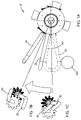
- FIG. 1 is a perspective view of a device for grasping an object, shown grasping the object, and constructed according to the teachings of the present disclosure
- FIG. 2A is a side view of the device and the object of FIG. 1 ;
- FIG. 2B is a bottom view of the device and the object of FIG. 1 ;
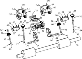
- FIG. 3 is an exploded view of the device of FIG. 1 ;
- FIG. 4 is an enlarged front view of one grabber assembly of FIG. 3 ;
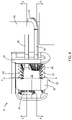
- FIG. 5 is a cross-sectional view, taken along line 5 - 5 of FIG. 4 illustrating a first arm extending through a shaft of the grabber assembly;
- FIG. 6 is a cross-sectional view, taken along line 6 - 6 of FIG. 4 illustrating a second arm extending through a shaft of the grabber assembly;
- FIG. 7A is an end view of portions of the grabber assembly illustrating arms in both an open position and a closed position according to the teachings of the present disclosure
- FIG. 7B is an end view of the arms of FIG. 8A in the open position
- FIG. 7C is an end view of the arms of FIG. 8A in the closed position
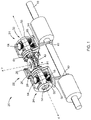
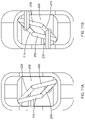
- FIG. 8 is a top perspective view of another form of a mechanical device for grasping an object without a power source and constructed according to the teachings of the present disclosure
- FIG. 9 is a bottom perspective view of the mechanical device of FIG. 8 ;
- FIG. 10 is an exploded perspective view of the mechanical device of FIG. 8 ;
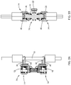
- FIG. 11A is a top view of the mechanical device of FIG. 8 ;
- FIG. 11B is a bottom view of the mechanical device of FIG. 8 ;
- FIG. 12 is a side view of the mechanical device of FIG. 8 .
- a mechanical device for grasping an object without a power source e.g., electricity, hydraulics, pneumatics
- the mechanical device comprises a receiver 22 and opposed grabber assemblies 24 .
- the receiver 22 is configured to be attached to an arm or component of an exoskeleton suit, or another robotic/automated mechanism (not shown).
- the receiver 22 in this form includes a platform 26 having a plurality of holes/openings 28 that receive bolts (not shown) to secure the receiver 22 to the arm/component of an exoskeleton suit or other robotic/automated mechanism.
- the opposed grabber assemblies 24 are secured to outboard portions of the receiver 22 and are arranged to grasp an object such as a shaft 10 . While two (2) opposed grabber assemblies are shown, it should be understood that the teachings of the present disclosure may be applied to at least one grabber assembly (one form of which is described in greater detail below) or more than two (2) grabber assemblies as illustrated herein. Further, the grabber assemblies 24 may be arranged in a variety of positions relative to the receiver 22 , and thus the opposed grabber assemblies 24 as illustrated and described herein should not be construed as limiting the scope of the present disclosure. In yet another variation, the receiver 22 is an optional component as a grabber assembly 24 may be directly secured to arm/component of an exoskeleton suit or other robotic/automated mechanism.
- each of the grabber assemblies 24 comprises a first arm 30 having a proximal end portion 32 , a distal end portion 34 , and a hook 36 disposed at the distal end portion 34 .
- a second arm 40 comprises a proximal end portion 42 , a distal end portion 44 , and a hook 46 disposed at the distal end portion 44 .
- each of the hooks 36 / 46 are integrally formed with each of the first and second arm 30 / 40 . In this form, each of the hooks 36 / 46 extend in opposite directions (best shown in FIG. 2B ) to facilitate grasping an object such as the shaft 10 .
- the hooks 36 / 46 may extend in the same direction, which would be beneficial in applications where the mechanical device 20 is used to grasp a wheel and the hooks 36 / 38 extend through spokes or lug nut holes in the wheel (not shown). Additionally, the hooks 36 / 38 may take on any geometric form or have additional functionality (e.g., magnets) while remaining within the scope of the present disclosure.
- each grabber assembly 24 includes a hub assembly 50 comprising a shaft 52 rotationally coupled to opposed bevel gears 54 .
- the opposed bevel gears 54 and the ends of the shaft 52 comprise races 56 (best shown in FIG. 3 ), which house bearings (not shown) to provide the rotational coupling around axis “X.”
- the shaft 52 further comprises a set of offset apertures 60 and 62 .
- the first arm 30 extends through one of the offset apertures 60 of the shaft 52
- the second arm 40 extends through the other offset aperture 62 .
- the first arm 30 further comprises a first bevel gear 64 disposed at the proximal end portion 32 and engaging one of the opposed bevel gears 54 .
- the second arm 40 further comprises a second bevel gear 66 disposed at the proximal end portion 42 and engaging the other opposed bevel gear 54 .
- each of the first arm 30 and the second arm 40 comprise a collar 70 , each of which engages a boss 72 on each shaft 52 (best shown in FIGS. 4 and 5 ).
- each of the first bevel gear 64 and the second bevel gear 66 comprise an end face 65 / 67 , respectively, which also engage the bosses 72 .
- the collars 70 and end faces 65 / 67 secure the first arm 30 and the second arm 40 to the shaft 52 .
- a variety of assembly approaches and component configurations may be employed to facilitate this design.
- the first bevel gear 64 and the second bevel gear 66 may be separate pieces that are secured in place after each of the first arm 30 and the second arm 40 are inserted through the offset apertures 60 / 62 .
- the shaft 52 may be a two-piece design (not shown), wherein each of the arms 30 / 40 are located in one half and the other half is subsequently secured around the arms 30 / 40 and the one half.
- the opposed bevel gears 54 are fixed in this form of the present disclosure. More specifically, the inner bevel gears 54 are secured to flanges 80 of a support frame 82 of the receiver 22 .
- the receiver 22 in this form comprises a center ring 84 opposite the platform 26 , which is rotationally mounted to the support frame 82 .
- the support frame 82 and the center ring 84 each includes races 86 , which house bearings (not shown) for the rotational movement around axis “Y” as shown.
- At least one shield 90 extends between the opposed bevel gears 54 and covers at least a portion of each opposed bevel gears 54 .
- three (3) shields 90 are employed, which are integrally formed with the opposed bevel gears 54 as a single/unitized part.
- any number of shields may be employed, which may be separate parts or formed integrally with the opposed bevel gears 54 as illustrated herein, while remaining within the scope of the present disclosure.
- the mechanical device 20 further comprises a stop to limit motion of the first and second arms 30 / 40 .
- the stop comprises a cage 94 secured to the flanges 80 of the support frame 82 of the receiver 22 .
- the cage 94 surrounds the first and second arms 30 / 40 .
- the cage 94 comprises a u-shaped bar that extends from one side of the cage 94 to the other. It should be understood that “surrounds” as used herein should be construed to mean completely surrounding as illustrated, or at least partially surrounding the first and second arms 30 / 40 .
- the cage 94 functions as a stop to limit motion of the first and second arms 30 / 40 , then any form thereof should be construed as falling within the scope of the present disclosure.
- the cage 94 is also secured to the flanges 80 of the support frame 82 of the receiver 22 . More specifically, in this form, the opposed bevel gears 54 are secured to the cage 94 , which is secured to the flange 80 . In the design illustrated, these components are secured together with bolts (not shown). However, it should be understood that other means to secure these components together, or combining these individual components into fewer parts, should be construed as falling within the scope of the present disclosure.
- FIGS. 7A-7C movement of the mechanical linkage, which in this form is a grabber assembly 24 with bevel gears, is illustrated in greater detail.
- a fixed object 100 in this example the first arm 30
- the mechanical device 20 is moved or translated from the receiver 22
- the first arm 30 rotates about the longitudinal axis “X” of the shaft via the rotational connection between the shaft 52 and the opposed bevel gears 54 .
- the shaft 52 rotates, and thus the bevel gear 64 rotates and engages bevel gear 54 .
- the second arm 40 With rotation of the shaft 52 , the second arm 40 also rotates, and its bevel gear 66 engages the opposed bevel gear 54 .
- This rotation of the shaft 52 which is caused by forces from the first arm 30 being displaced against the fixed object 100 , opens the arms 30 / 40 so that the hooks 36 / 46 can be placed around the fixed object 100 .
- the mechanical device 20 is translated into position such that the hooks 36 / 46 are around the fixed object 100 , then the first arm 30 is placed against the fixed object again in an opposite direction to cause the first and second arms 30 / 40 to rotate in the opposite direction to close the hooks 36 / 46 around the fixed object 100 .
- the first arm 30 (or the second arm 40 ) is displaced against the fixed object 100 to open the hooks 36 / 46 .
- the first and second arms 30 / 40 may be displaced against any fixed object other than the fixed object 100 being grasped.
- the fixed object need not be statically “fixed,” and rather the fixed object should only be rigid enough to cause movement of one of the first or second arms 30 / 40 without the fixed object moving itself. Therefore, displacement of the first arm 30 or the second arm 40 against an object causes movement of the mechanical linkage (in this form the bevel gears) and thus movement of the second arm 40 or first arm 30 , respectively.
- the mechanical device 200 comprises a central frame 202 , a first arm 204 and a second arm 206 extending through the central frame 202 .
- Each of the first arm 204 and second arm 206 comprise upper links 208 and lower links 210 .
- the mechanical device 200 further includes a pair of upper opposed receivers 220 , each upper opposed receiver 220 comprising an arm 224 with end portions 226 .
- Each end portion 226 is pivotally coupled to the upper links 208 of the first arm 204 and the second arm 206 .
- a pair of lower opposed receivers 230 each similarly comprise an arm 232 with end portions 234 .
- Each end portion 234 is pivotally coupled to the lower links 210 of the first arm 204 and the second arm 206 , respectively.
- each of the upper opposed receivers 220 and the lower opposed receivers 230 comprise a slot 236 (best shown in FIG. 10 ).
- Each of the upper links 208 and the lower links 210 are disposed within a respective slot as shown so that their rotational movement can be accommodated.
- the mechanical device 200 also includes a stop to limit motion of at least one of the first arm 204 and the second arm 206 . More specifically, a cage 250 is secured to the central frame 202 . In this form, the central frame 202 includes opposed tabs 252 that are disposed within apertures 254 of the cage 250 .
- the upper receiver 220 and the lower receiver 230 in this form include pins 260 , which are disposed within slots 264 of the cage 250 .
- the slots 264 are provided to allow some vertical “play” of the first arm 204 and the second arm 206 during operation.
- displacement of the first arm 204 or the second arm 206 against an object causes rotation of the lower opposed receivers 230 and the upper opposed receivers 220 and thus movement of the second arm 206 or first arm 204 , respectively.
- Similar features such as the hooks 36 / 46 as described above are not repeated with this variation for purposes of brevity.
- the method comprises moving the mechanical device as set forth herein and engaging the first arm or the second arm against an object.
- the object displaces the arm being engaged with the object, which causes movement of the mechanical linkage, which causes movement of the other arm. Accordingly, each of the arms may be moved against an object to open or close the arm, thereby grasping and releasing the object.
- the mechanical linkage disposed near the proximal end portion of the first arm and the second arm kinematically couples the first arm and the second arm, wherein displacement of the first arm or the second arm against the object causes movement of the mechanical linkage, which causes movement of the second arm or first arm, respectively.
- Grasping an object “without a power source” as used herein should be construed to mean grasping an object by only mechanical movement of the first and second arms as illustrated and described herein.
- the phrase at least one of A, B, and C should be construed to mean a logical (A OR B OR C), using a non-exclusive logical OR, and should not be construed to mean “at least one of A, at least one of B, and at least one of C.”
Landscapes
- Engineering & Computer Science (AREA)
- Mechanical Engineering (AREA)
- Robotics (AREA)
- General Engineering & Computer Science (AREA)
- Manipulator (AREA)
Abstract
Description
- The present disclosure relates to robotic systems and exoskeleton suits with end effectors, and more particularly to end effectors that are configured to grasp and move objects.
- The statements in this section merely provide background information related to the present disclosure and may not constitute prior art.
- Industrial robots have been used for a variety of manufacturing operations, including by way of example, welding, placement of parts for subsequent fabrication or assembly operations, and moving parts from one location to another such as retrieving parts from a storage location and moving them to an assembly station. These industrial robots include end effectors, which are essentially the hands of the robot. In many applications, the end effectors are configured as grippers, which grasp a part and move the part to a different location or manipulate the position of the part for manufacturing operations.
- Recently, exoskeleton suits have been developed, which are wearable mobile robotic accessories powered by electric motors, pneumatics or hydraulics, or other systems to allow a user to have increased strength and endurance when performing various operations, such as industrial manufacturing operations. These exoskeleton suits also have end effectors, which come in a variety of configurations depending on the particular manufacturing operation. However, exoskeleton suits are often heavy and cumbersome, as power is required for their operation. In some environments, power may not be available, or power from a battery may be dissipated before completion of the manufacturing task using the exoskeleton suit.
- These issues related to exoskeleton suits, among other issues related to robotic end effectors, are addressed by the present disclosure.
- This section provides a general summary of the disclosure and is not a comprehensive disclosure of its full scope or all of its features.
- In one form, a mechanical device for grasping an object without a power source is provided that includes a receiver, at least one grabber assembly secured to the receiver, the at least one grabber assembly comprising a first arm comprising a proximal end portion and a distal end portion, and a hook disposed at the distal end portion. A second arm comprising a proximal end portion and a distal end portion, and a hook disposed at the distal end portion. A mechanical linkage is disposed near the proximal end portion of the first arm and the second arm, the mechanical linkage kinematically coupling the first arm to the second arm. Displacement of the first arm or the second arm against the object causes movement of the mechanical linkage and thus movement of the second arm or first arm, respectively.
- In one variation of the mechanical device, the mechanical linkage comprises a hub assembly comprising a shaft rotationally coupled to opposed bevel gears, the shaft comprising a set of offset apertures. The first arm extends through one of the offset apertures of the shaft, the first arm further comprising a first bevel gear disposed at the proximal end portion and engaging one of the opposed bevel gears. The second arm extends through another one of the offset apertures, the second arm further comprising a second bevel gear disposed at the proximal end portion and engaging another one of the opposed bevel gears. Movement of the mechanical linkage comprises rotation of the shaft.
- In variations of this bevel gear design, which may be employed individually or in any combination: the opposed bevel gears are fixed; at least one shield extends between the opposed bevel gears, wherein the shield covers at least a portion of each opposed bevel gear; each of the hooks comprise are integrally formed with each of the first and second arm; each of the hooks of the first and second arms extend in opposite directions; each of the hooks of the first and second arms extend in the same direction; a stop is configured to limit motion of at least one of the first arm and the second arm; and the stop comprises a cage surrounding the first arm and the second arm.
- In another design configuration, the mechanical linkage comprises a central frame, each of the first arm and second arm extending through the central frame, and each of the first arm and second arm comprising upper and lower links. A pair of upper opposed receivers each comprise an arm with end portions, each end portion being pivotally coupled to the upper links of the first arm and the second arm. A pair of lower opposed receivers each comprise an arm with end portions, each end portion being pivotally coupled to the lower links of the first arm and the second arm. The displacement of the first arm or the second arm against the object causes rotation of the lower opposed receivers and the upper opposed receivers and thus movement of the second arm or first arm, respectively.
- In variations of this second configuration with links, which may be employed individually or in any combination: a stop is configured to limit motion of at least one of the first arm and the second arm; the stop comprises a cage secured to the central frame; and each of the pair of upper opposed receivers and lower opposed receivers comprises a slot, each of the upper and lower links being disposed within a respective slot.
- In yet another form of the present disclosure, a mechanical device for grasping an object without a power source comprises a receiver and opposed grabber assemblies secured to outboard portions of the receiver. Each grabber assembly comprises a first arm comprising a proximal end portion and a distal end portion, and a hook disposed at the distal end portion. A second arm comprises a proximal end portion and a distal end portion, and a hook disposed at the distal end portion. A mechanical linkage is disposed near the proximal end portion of the first arm and the second arm, the mechanical linkage kinematically coupling the first arm and the second arm. Displacement of the first arm or the second arm against the object causes movement of the mechanical linkage and thus movement of the second arm or first arm, respectively.
- In one variation of this design with opposed grabber assemblies, the mechanical linkage comprises a hub assembly comprising a shaft rotationally coupled to opposed bevel gears, the shaft comprising a set of offset apertures. The first arm extends through one of the offset apertures of the hub, the first arm further comprising a first bevel gear disposed at the proximal end portion and engaging one of the opposed bevel gears. The second arm extends through another one of the offset apertures, the second arm further comprising a second bevel gear disposed at the proximal end portion and engaging another one of the opposed bevel gears. Movement of the mechanical linkage comprises rotation of the shaft.
- In variations of this design with opposed grabber assemblies, which may be employed individually or in any combination: each of the hooks of the first and second arms extend in opposite directions; each of the hooks of the first and second arms extend in the same direction; a stop is configured to limit motion of at least one of the first arm and the second arm; and the stop comprises a cage surrounding the first arm and the second arm.
- In yet another form of the present disclosure, a method of grasping an object without a power source comprises moving a mechanical device, the mechanical device comprising a first arm comprising a proximal end portion and a distal end portion, and a hook disposed at the distal end portion, a second arm comprising a proximal end portion and a distal end portion, and a hook disposed at the distal end portion, and a mechanical linkage disposed near the proximal end portion of the first arm and the second arm, wherein the mechanical linkage kinematically couples the first arm and the second arm. Moving the device comprises engaging the first arm or the second arm against the object, wherein the object displaces the arm being engaged with the object, which causes movement of the mechanical linkage and the other arm.
- Further areas of applicability will become apparent from the description provided herein. It should be understood that the description and specific examples are intended for purposes of illustration only and are not intended to limit the scope of the present disclosure.
- In order that the disclosure may be well understood, there will now be described various forms thereof, given by way of example, reference being made to the accompanying drawings, in which:
-
FIG. 1 is a perspective view of a device for grasping an object, shown grasping the object, and constructed according to the teachings of the present disclosure; -
FIG. 2A is a side view of the device and the object ofFIG. 1 ; -
FIG. 2B is a bottom view of the device and the object ofFIG. 1 ; -
FIG. 3 is an exploded view of the device ofFIG. 1 ; -
FIG. 4 is an enlarged front view of one grabber assembly ofFIG. 3 ; -
FIG. 5 is a cross-sectional view, taken along line 5-5 ofFIG. 4 illustrating a first arm extending through a shaft of the grabber assembly; -
FIG. 6 is a cross-sectional view, taken along line 6-6 ofFIG. 4 illustrating a second arm extending through a shaft of the grabber assembly; -
FIG. 7A is an end view of portions of the grabber assembly illustrating arms in both an open position and a closed position according to the teachings of the present disclosure; -
FIG. 7B is an end view of the arms ofFIG. 8A in the open position; -
FIG. 7C is an end view of the arms ofFIG. 8A in the closed position; -
FIG. 8 is a top perspective view of another form of a mechanical device for grasping an object without a power source and constructed according to the teachings of the present disclosure; -
FIG. 9 is a bottom perspective view of the mechanical device ofFIG. 8 ; -
FIG. 10 is an exploded perspective view of the mechanical device ofFIG. 8 ; -
FIG. 11A is a top view of the mechanical device ofFIG. 8 ; -
FIG. 11B is a bottom view of the mechanical device ofFIG. 8 ; and -
FIG. 12 is a side view of the mechanical device ofFIG. 8 . - The drawings described herein are for illustration purposes only and are not intended to limit the scope of the present disclosure in any way.
- The following description is merely exemplary in nature and is not intended to limit the present disclosure, application, or uses. It should be understood that throughout the drawings, corresponding reference numerals indicate like or corresponding parts and features.
- Referring to
FIGS. 1-3 , a mechanical device for grasping an object without a power source (e.g., electricity, hydraulics, pneumatics) is illustrated and generally indicated byreference numeral 20. The mechanical device comprises areceiver 22 andopposed grabber assemblies 24. Thereceiver 22 is configured to be attached to an arm or component of an exoskeleton suit, or another robotic/automated mechanism (not shown). Accordingly, thereceiver 22 in this form includes aplatform 26 having a plurality of holes/openings 28 that receive bolts (not shown) to secure thereceiver 22 to the arm/component of an exoskeleton suit or other robotic/automated mechanism. - The
opposed grabber assemblies 24 are secured to outboard portions of thereceiver 22 and are arranged to grasp an object such as ashaft 10. While two (2) opposed grabber assemblies are shown, it should be understood that the teachings of the present disclosure may be applied to at least one grabber assembly (one form of which is described in greater detail below) or more than two (2) grabber assemblies as illustrated herein. Further, thegrabber assemblies 24 may be arranged in a variety of positions relative to thereceiver 22, and thus theopposed grabber assemblies 24 as illustrated and described herein should not be construed as limiting the scope of the present disclosure. In yet another variation, thereceiver 22 is an optional component as agrabber assembly 24 may be directly secured to arm/component of an exoskeleton suit or other robotic/automated mechanism. - As best shown in
FIG. 3 , each of thegrabber assemblies 24 comprises afirst arm 30 having aproximal end portion 32, adistal end portion 34, and ahook 36 disposed at thedistal end portion 34. Similarly, asecond arm 40 comprises aproximal end portion 42, adistal end portion 44, and ahook 46 disposed at thedistal end portion 44. As shown, each of thehooks 36/46 are integrally formed with each of the first andsecond arm 30/40. In this form, each of thehooks 36/46 extend in opposite directions (best shown inFIG. 2B ) to facilitate grasping an object such as theshaft 10. However, it should be understood that thehooks 36/46 may extend in the same direction, which would be beneficial in applications where themechanical device 20 is used to grasp a wheel and thehooks 36/38 extend through spokes or lug nut holes in the wheel (not shown). Additionally, thehooks 36/38 may take on any geometric form or have additional functionality (e.g., magnets) while remaining within the scope of the present disclosure. - Referring also to
FIGS. 4-6 , eachgrabber assembly 24 includes ahub assembly 50 comprising ashaft 52 rotationally coupled to opposed bevel gears 54. In one form, theopposed bevel gears 54 and the ends of theshaft 52 comprise races 56 (best shown inFIG. 3 ), which house bearings (not shown) to provide the rotational coupling around axis “X.” - The
shaft 52 further comprises a set of offsetapertures first arm 30 extends through one of the offsetapertures 60 of theshaft 52, and thesecond arm 40 extends through the other offsetaperture 62. Thefirst arm 30 further comprises afirst bevel gear 64 disposed at theproximal end portion 32 and engaging one of the opposed bevel gears 54. Similarly, thesecond arm 40 further comprises asecond bevel gear 66 disposed at theproximal end portion 42 and engaging the otheropposed bevel gear 54. - In one form, each of the
first arm 30 and thesecond arm 40 comprise acollar 70, each of which engages aboss 72 on each shaft 52 (best shown inFIGS. 4 and 5 ). As further shown, each of thefirst bevel gear 64 and thesecond bevel gear 66 comprise anend face 65/67, respectively, which also engage thebosses 72. Accordingly, thecollars 70 and end faces 65/67 secure thefirst arm 30 and thesecond arm 40 to theshaft 52. A variety of assembly approaches and component configurations may be employed to facilitate this design. For example, thefirst bevel gear 64 and thesecond bevel gear 66 may be separate pieces that are secured in place after each of thefirst arm 30 and thesecond arm 40 are inserted through the offsetapertures 60/62. Alternately, theshaft 52 may be a two-piece design (not shown), wherein each of thearms 30/40 are located in one half and the other half is subsequently secured around thearms 30/40 and the one half. - Referring back to
FIG. 1 and alsoFIG. 3 , theopposed bevel gears 54 are fixed in this form of the present disclosure. More specifically, theinner bevel gears 54 are secured toflanges 80 of asupport frame 82 of thereceiver 22. Thereceiver 22 in this form comprises acenter ring 84 opposite theplatform 26, which is rotationally mounted to thesupport frame 82. Thesupport frame 82 and thecenter ring 84 each includesraces 86, which house bearings (not shown) for the rotational movement around axis “Y” as shown. - As further shown, at least one
shield 90 extends between theopposed bevel gears 54 and covers at least a portion of each opposed bevel gears 54. In this form, three (3) shields 90 are employed, which are integrally formed with theopposed bevel gears 54 as a single/unitized part. However, it should be understood that any number of shields may be employed, which may be separate parts or formed integrally with theopposed bevel gears 54 as illustrated herein, while remaining within the scope of the present disclosure. - The
mechanical device 20 further comprises a stop to limit motion of the first andsecond arms 30/40. In this form, the stop comprises acage 94 secured to theflanges 80 of thesupport frame 82 of thereceiver 22. As shown, thecage 94 surrounds the first andsecond arms 30/40. More specifically, thecage 94 comprises a u-shaped bar that extends from one side of thecage 94 to the other. It should be understood that “surrounds” as used herein should be construed to mean completely surrounding as illustrated, or at least partially surrounding the first andsecond arms 30/40. As long as thecage 94 functions as a stop to limit motion of the first andsecond arms 30/40, then any form thereof should be construed as falling within the scope of the present disclosure. As further shown, thecage 94 is also secured to theflanges 80 of thesupport frame 82 of thereceiver 22. More specifically, in this form, theopposed bevel gears 54 are secured to thecage 94, which is secured to theflange 80. In the design illustrated, these components are secured together with bolts (not shown). However, it should be understood that other means to secure these components together, or combining these individual components into fewer parts, should be construed as falling within the scope of the present disclosure. - Referring now to
FIGS. 7A-7C in conjunction withFIG. 1 , movement of the mechanical linkage, which in this form is agrabber assembly 24 with bevel gears, is illustrated in greater detail. When thefirst arm 30 or thesecond arm 40 is physically placed against a fixedobject 100, (in this example the first arm 30), and themechanical device 20 is moved or translated from thereceiver 22, this causes movement of the mechanical linkage. More specifically, thefirst arm 30 rotates about the longitudinal axis “X” of the shaft via the rotational connection between theshaft 52 and the opposed bevel gears 54. As thefirst arm 30 rotates, theshaft 52 rotates, and thus thebevel gear 64 rotates and engagesbevel gear 54. With rotation of theshaft 52, thesecond arm 40 also rotates, and itsbevel gear 66 engages the opposedbevel gear 54. This rotation of theshaft 52, which is caused by forces from thefirst arm 30 being displaced against the fixedobject 100, opens thearms 30/40 so that thehooks 36/46 can be placed around the fixedobject 100. Then, themechanical device 20 is translated into position such that thehooks 36/46 are around the fixedobject 100, then thefirst arm 30 is placed against the fixed object again in an opposite direction to cause the first andsecond arms 30/40 to rotate in the opposite direction to close thehooks 36/46 around the fixedobject 100. To release the fixedobject 100, the first arm 30 (or the second arm 40) is displaced against the fixedobject 100 to open thehooks 36/46. It should be understood that the first andsecond arms 30/40 may be displaced against any fixed object other than the fixedobject 100 being grasped. Further, the fixed object need not be statically “fixed,” and rather the fixed object should only be rigid enough to cause movement of one of the first orsecond arms 30/40 without the fixed object moving itself. Therefore, displacement of thefirst arm 30 or thesecond arm 40 against an object causes movement of the mechanical linkage (in this form the bevel gears) and thus movement of thesecond arm 40 orfirst arm 30, respectively. - Referring now to
FIGS. 8-12 , another form of a mechanical device according to the present disclosure is illustrated and generally indicated byreference numeral 200. In this form, themechanical device 200 comprises acentral frame 202, afirst arm 204 and asecond arm 206 extending through thecentral frame 202. Each of thefirst arm 204 andsecond arm 206 compriseupper links 208 andlower links 210. Themechanical device 200 further includes a pair of upperopposed receivers 220, each upperopposed receiver 220 comprising anarm 224 withend portions 226. Eachend portion 226 is pivotally coupled to theupper links 208 of thefirst arm 204 and thesecond arm 206. A pair of loweropposed receivers 230 each similarly comprise anarm 232 withend portions 234. Eachend portion 234 is pivotally coupled to thelower links 210 of thefirst arm 204 and thesecond arm 206, respectively. In one form, each of the upperopposed receivers 220 and the loweropposed receivers 230 comprise a slot 236 (best shown inFIG. 10 ). Each of theupper links 208 and thelower links 210 are disposed within a respective slot as shown so that their rotational movement can be accommodated. - Similar to the previous form of the present disclosure, the
mechanical device 200 also includes a stop to limit motion of at least one of thefirst arm 204 and thesecond arm 206. More specifically, acage 250 is secured to thecentral frame 202. In this form, thecentral frame 202 includes opposedtabs 252 that are disposed within apertures 254 of thecage 250. - As further shown, the
upper receiver 220 and thelower receiver 230 in this form includepins 260, which are disposed withinslots 264 of thecage 250. Theslots 264 are provided to allow some vertical “play” of thefirst arm 204 and thesecond arm 206 during operation. - Accordingly, similar to the previously described form with bevel gears, displacement of the
first arm 204 or thesecond arm 206 against an object causes rotation of the loweropposed receivers 230 and the upperopposed receivers 220 and thus movement of thesecond arm 206 orfirst arm 204, respectively. Similar features such as thehooks 36/46 as described above are not repeated with this variation for purposes of brevity. - Referring to
FIG. 13 , a method of grasping an object without a power source according to the present disclosure is illustrated. The method comprises moving the mechanical device as set forth herein and engaging the first arm or the second arm against an object. The object displaces the arm being engaged with the object, which causes movement of the mechanical linkage, which causes movement of the other arm. Accordingly, each of the arms may be moved against an object to open or close the arm, thereby grasping and releasing the object. - Advantageously, the mechanical linkage disposed near the proximal end portion of the first arm and the second arm kinematically couples the first arm and the second arm, wherein displacement of the first arm or the second arm against the object causes movement of the mechanical linkage, which causes movement of the second arm or first arm, respectively.
- Grasping an object “without a power source” as used herein should be construed to mean grasping an object by only mechanical movement of the first and second arms as illustrated and described herein.
- Unless otherwise expressly indicated herein, all numerical values indicating mechanical/thermal properties, compositional percentages, dimensions and/or tolerances, or other characteristics are to be understood as modified by the word “about” or “approximately” in describing the scope of the present disclosure. This modification is desired for various reasons including industrial practice, material, manufacturing, and assembly tolerances, and testing capability.
- As used herein, the phrase at least one of A, B, and C should be construed to mean a logical (A OR B OR C), using a non-exclusive logical OR, and should not be construed to mean “at least one of A, at least one of B, and at least one of C.”
- The description of the disclosure is merely exemplary in nature and, thus, variations that do not depart from the substance of the disclosure are intended to be within the scope of the disclosure. Such variations are not to be regarded as a departure from the spirit and scope of the disclosure.
Claims (20)
Priority Applications (2)
| Application Number | Priority Date | Filing Date | Title |
|---|---|---|---|
| US17/122,947 US11858137B2 (en) | 2020-12-15 | 2020-12-15 | Mechanical grasping end effector with horizontal and vertical movement |
| CN202111503134.1A CN114633278A (en) | 2020-12-15 | 2021-12-09 | Mechanical grasping end effector capable of horizontal movement and vertical movement |
Applications Claiming Priority (1)
| Application Number | Priority Date | Filing Date | Title |
|---|---|---|---|
| US17/122,947 US11858137B2 (en) | 2020-12-15 | 2020-12-15 | Mechanical grasping end effector with horizontal and vertical movement |
Publications (2)
| Publication Number | Publication Date |
|---|---|
| US20220184800A1 true US20220184800A1 (en) | 2022-06-16 |
| US11858137B2 US11858137B2 (en) | 2024-01-02 |
Family
ID=81943015
Family Applications (1)
| Application Number | Title | Priority Date | Filing Date |
|---|---|---|---|
| US17/122,947 Active 2042-03-25 US11858137B2 (en) | 2020-12-15 | 2020-12-15 | Mechanical grasping end effector with horizontal and vertical movement |
Country Status (2)
| Country | Link |
|---|---|
| US (1) | US11858137B2 (en) |
| CN (1) | CN114633278A (en) |
Citations (5)
| Publication number | Priority date | Publication date | Assignee | Title |
|---|---|---|---|---|
| US3306646A (en) * | 1965-07-30 | 1967-02-28 | Flexicore Company Inc | Lifting hook assembly |
| US5024575A (en) * | 1989-09-08 | 1991-06-18 | Robotic Originals, Inc. | Lightweight gripper for robotic transfer operations |
| US7455338B2 (en) * | 2005-10-07 | 2008-11-25 | Jenney Alfred P | Leveling device for lifting apparatus and associated methods |
| US8414042B2 (en) * | 2007-10-15 | 2013-04-09 | Delaware Capital Formation, Inc. | Articulating package palletizing system |
| US10995876B2 (en) * | 2019-06-12 | 2021-05-04 | Chun Kuen Sze | Electro-mechanical valve servo apparatus for tool-free retrofit installation |
Family Cites Families (4)
| Publication number | Priority date | Publication date | Assignee | Title |
|---|---|---|---|---|
| US5108140A (en) | 1988-04-18 | 1992-04-28 | Odetics, Inc. | Reconfigurable end effector |
| CN2672015Y (en) | 2003-12-12 | 2005-01-19 | 涟源钢铁集团有限公司 | Hydraulic drive gripping apparatus for strip section bar |
| CN107650140A (en) | 2017-11-10 | 2018-02-02 | 肇庆乐创科技有限公司 | A kind of adjustable handgrip for robot palletizer |
| CN108100659B (en) | 2018-01-31 | 2024-04-19 | 青岛宝佳智能装备股份有限公司 | Robot end effector suitable for carrying bagged materials in compact space |
-
2020
- 2020-12-15 US US17/122,947 patent/US11858137B2/en active Active
-
2021
- 2021-12-09 CN CN202111503134.1A patent/CN114633278A/en active Pending
Patent Citations (5)
| Publication number | Priority date | Publication date | Assignee | Title |
|---|---|---|---|---|
| US3306646A (en) * | 1965-07-30 | 1967-02-28 | Flexicore Company Inc | Lifting hook assembly |
| US5024575A (en) * | 1989-09-08 | 1991-06-18 | Robotic Originals, Inc. | Lightweight gripper for robotic transfer operations |
| US7455338B2 (en) * | 2005-10-07 | 2008-11-25 | Jenney Alfred P | Leveling device for lifting apparatus and associated methods |
| US8414042B2 (en) * | 2007-10-15 | 2013-04-09 | Delaware Capital Formation, Inc. | Articulating package palletizing system |
| US10995876B2 (en) * | 2019-06-12 | 2021-05-04 | Chun Kuen Sze | Electro-mechanical valve servo apparatus for tool-free retrofit installation |
Also Published As
| Publication number | Publication date |
|---|---|
| CN114633278A (en) | 2022-06-17 |
| US11858137B2 (en) | 2024-01-02 |
Similar Documents
| Publication | Publication Date | Title |
|---|---|---|
| US8443694B2 (en) | Rotary series elastic actuator | |
| US8424824B1 (en) | Balancer swivel arm assembly | |
| US8467903B2 (en) | Tendon driven finger actuation system | |
| US10906193B2 (en) | Manufacturing system, method of constructing the manufacturing system, end effector, robot, and working method of robot | |
| US4762016A (en) | Robotic manipulator having three degrees of freedom | |
| US5197846A (en) | Six-degree-of-freedom articulated robot mechanism and assembling and working apparatus using same | |
| US20110232411A1 (en) | Robot arm assembly | |
| US20160221197A1 (en) | Robotic Arm and Wrist Mechanisms | |
| US20130189063A1 (en) | Industrial Robot Including A Parallel Kinematic Manipulator | |
| TW201932256A (en) | An industrial robot arm | |
| US20110154932A1 (en) | Robot arm assembly and robot using the same | |
| KR20150043995A (en) | Method for handling objects by means of at least two industrial robots, and related industrial robot | |
| CN104416580A (en) | Joint driving device and robot | |
| US8601899B2 (en) | Hybrid serial-parallel linkage based six degrees of freedom robotic manipulator | |
| US11858137B2 (en) | Mechanical grasping end effector with horizontal and vertical movement | |
| US20130125690A1 (en) | Robot arm assembly | |
| CN112549003A (en) | Five-axis robot moving platform and five-axis robot thereof | |
| JPH05237789A (en) | Joint device | |
| US20250046482A1 (en) | Mechanical grasping end effector with linear engagement and disengagement movement | |
| CN115890717B (en) | Mechanical arm | |
| KR101984543B1 (en) | Robot gripper capable of various task depending on the object to be grasped | |
| CN116476107A (en) | A Humanoid Manipulator Based on Link Mechanism and Gear Transmission | |
| Ihrke et al. | Rotary series elastic actuator | |
| CN214187181U (en) | Five-axis robot moving platform and five-axis robot thereof | |
| JPH0241888A (en) | Supporting mechanism for rotation driving shaft of industrial robot |
Legal Events
| Date | Code | Title | Description |
|---|---|---|---|
| FEPP | Fee payment procedure |
Free format text: ENTITY STATUS SET TO UNDISCOUNTED (ORIGINAL EVENT CODE: BIG.); ENTITY STATUS OF PATENT OWNER: LARGE ENTITY |
|
| AS | Assignment |
Owner name: FORD GLOBAL TECHNOLOGIES, LLC, MICHIGAN Free format text: ASSIGNMENT OF ASSIGNORS INTEREST;ASSIGNOR:MODZEL, JOHN;REEL/FRAME:055602/0775 Effective date: 20201215 |
|
| STPP | Information on status: patent application and granting procedure in general |
Free format text: DOCKETED NEW CASE - READY FOR EXAMINATION |
|
| STPP | Information on status: patent application and granting procedure in general |
Free format text: NON FINAL ACTION MAILED |
|
| STPP | Information on status: patent application and granting procedure in general |
Free format text: RESPONSE TO NON-FINAL OFFICE ACTION ENTERED AND FORWARDED TO EXAMINER |
|
| STPP | Information on status: patent application and granting procedure in general |
Free format text: NOTICE OF ALLOWANCE MAILED -- APPLICATION RECEIVED IN OFFICE OF PUBLICATIONS |
|
| STPP | Information on status: patent application and granting procedure in general |
Free format text: PUBLICATIONS -- ISSUE FEE PAYMENT RECEIVED |
|
| STPP | Information on status: patent application and granting procedure in general |
Free format text: PUBLICATIONS -- ISSUE FEE PAYMENT VERIFIED |
|
| STCF | Information on status: patent grant |
Free format text: PATENTED CASE |